¶ Introduction
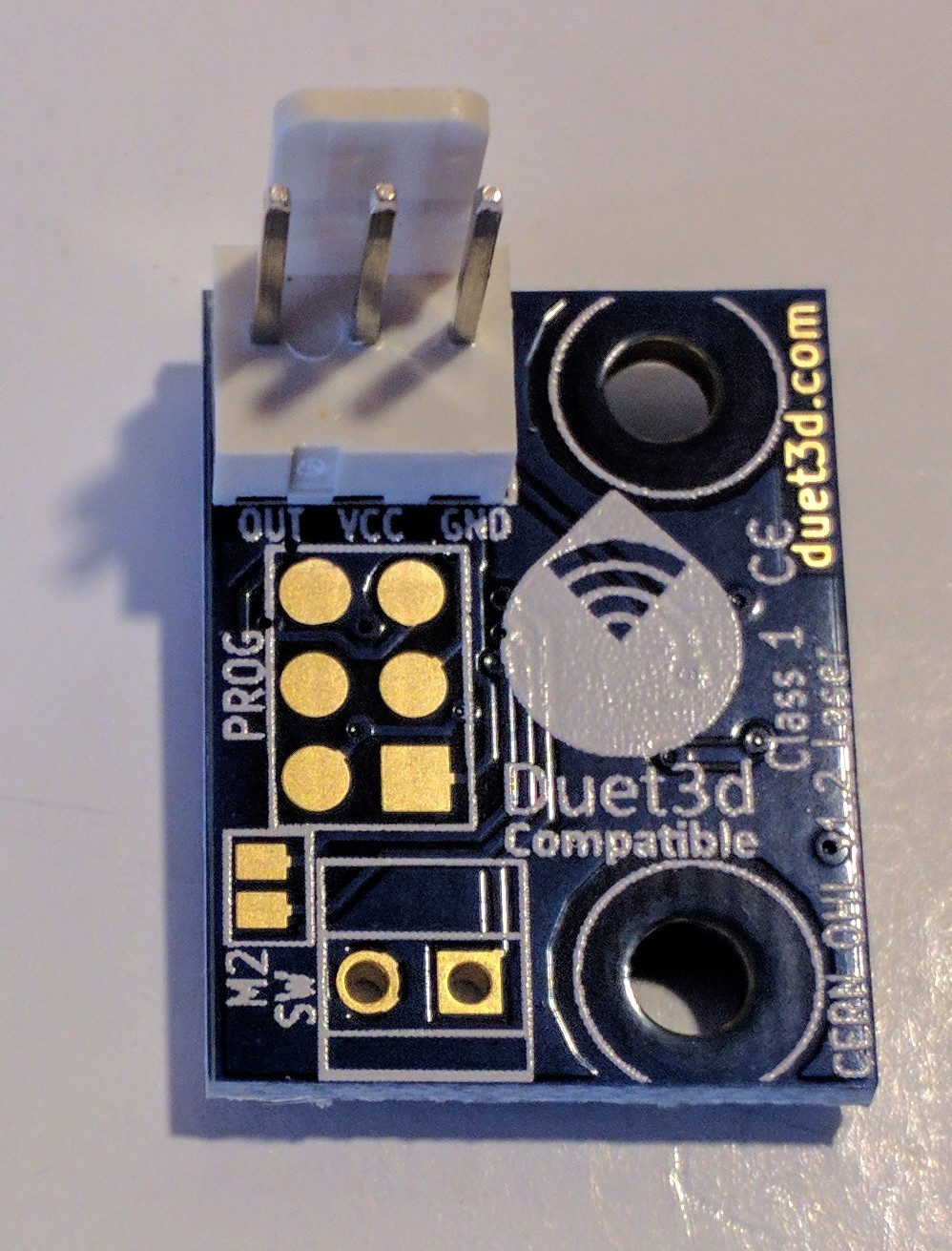
The Duet3D filament monitors sense filament movement and so can indicate that filament has run out, jammed or has been ground away in the extruder. This version uses a laser sensor to detect movement.
The Duet3D Laser filament monitor is no longer under production as better results across filament types and colours are achieved using the Rotating Magnet Filament Monitor.
¶ How it works
- Filament moving through the filament monitor is detected by the laser optical sensor. The microcontroller in the filament monitor reads the amount and direction of motion and periodically sends the accumulated amount of motion to the Duet.
- When net extruder movement greater than the number of mm configured in the E parameter (for example 3mm) has been commanded, the extrusion measured by the filament monitor is compared with the amount of extrusion commanded.
- If the difference between what has been commanded and what has been measured by the filament monitor is greater than the configured tolerance (configured using the R parameter), the print is paused and an error is reported.
¶ Note on filament compatibility
Different filament materials and colours are detected with varying degrees of accuracy by the laser sensor. For most filament types this can be handled through setting an appropriate trigger value for the sensor. The sensor is accurate enough in most tested filaments to allow the print to be paused for filament run-out, jam or tangle, those filament types the sensor is less sensitive to may have 1-2mm of error in movement detection. Depending on where in the print the extruder jam or filament strip occurs will determine how much of an impact 1-2mm of unfed filament will have on the print. The sensor is proving to be inaccurate with certain PETG filament, especially from ESUN (Black tested so far) and is not recommended for this.
¶ Hardware
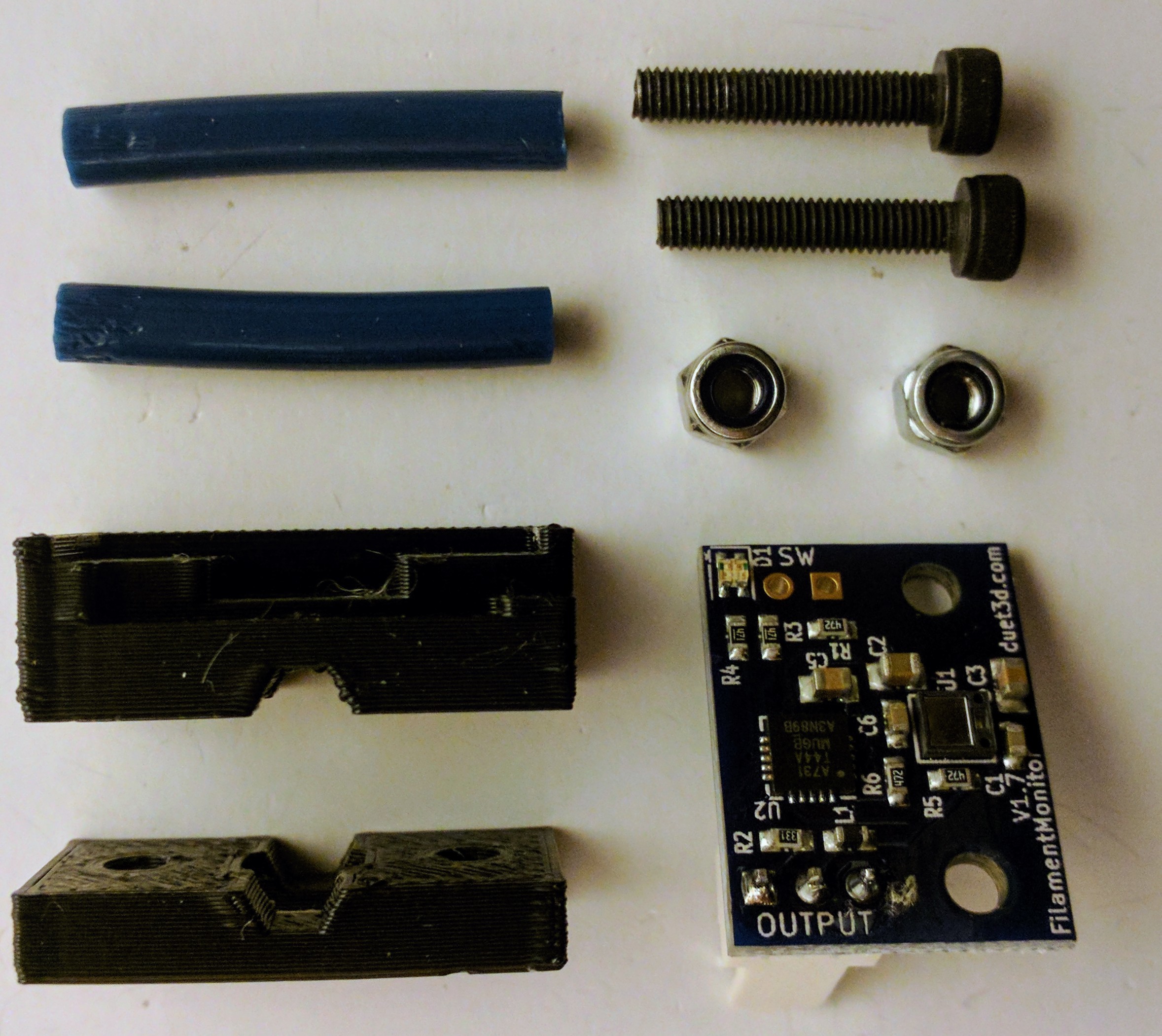
The filament monitor consists of a PCB which carries a laser optical sensor, a 2-part printed housing, and short PTFE inlet and outlet tubes to guide the filament.
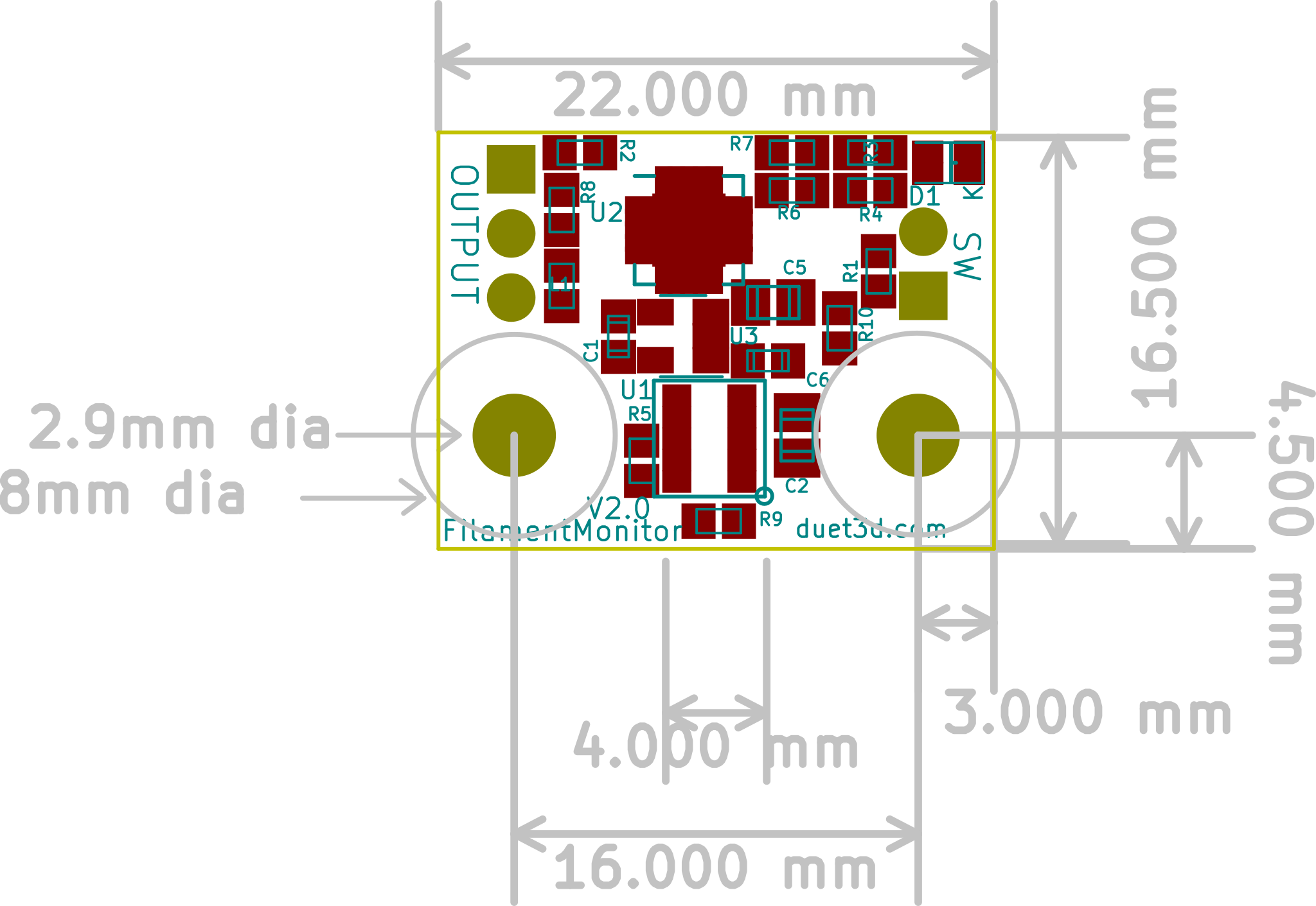
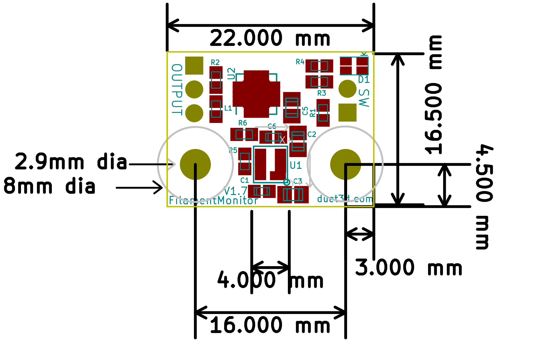
Both revisions have the same Laser sensor position, PCB dimensions and mounting holes. Some of the components are in different locations which can affect the housing which is why there are two different housing desings.
¶ Dimensions
¶ 3D printable parts
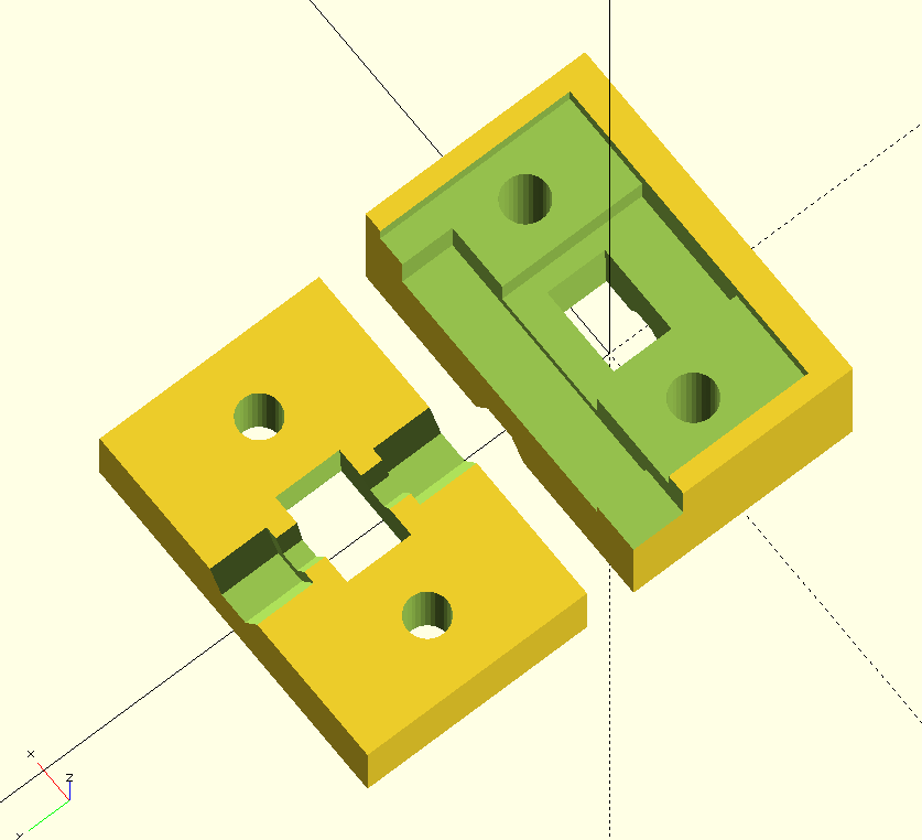
The Laser Filament Monitor uses two printed parts to constrain the filament so that it passes over the centre of the the optical sensor at the correct height. Inlet and outlet PTFE tubes are clamped between these two parts. They must be printed in black filament.
OpenSCAD source and STLs from DC42's reference housing design can be found here on GitHub.
¶ Dimensions
¶ 3D printable parts
The Laser Filament Monitor uses two printed parts to constrain the filament so that it passes over the centre of the the optical sensor at the correct height. Inlet and outlet PTFE tubes are clamped between these two parts. They must be printed in black filament.
The OpenSCAD source file and STL for these parts is available on Github here.
Base plate / Filament Block
This part fits on top of the PCB.
Top plate / Sensor Block
This fits on top of the base plate, The PTFE inlet and outlet tubes are clamped between the two plates.
¶ Open Source
The hardware source files are on Github here.
¶ Other parts
| Component | Quantity | Notes |
|---|---|---|
| M3x25 screw | 2 | The screw length depends on the housing design, also longer screws if you wish to secure the filament monitor to something else |
| M3 nut | 2 | Use Nyloc nuts or thread lock for security |
| M3 nylon washers | 2 | Optional |
| 4mm OD x 1.8mm ID PTFE tubing | 2 pieces | Preferably Capricorn or similar quality. One length is for the filament inlet and need only be a few cm long, but can be longer if you need to guide the filament from the spool. The other is for the filament outlet and must be long enough to reach the extruder drive, but short enough for the filament monitor to sense retraction accurately. |
¶ Temperature Limits
Max recommended operating temperature specified by the manufacturer of the laser sensor device is 60C. All other electronic parts are rated to 85C or more.
¶ Assembly
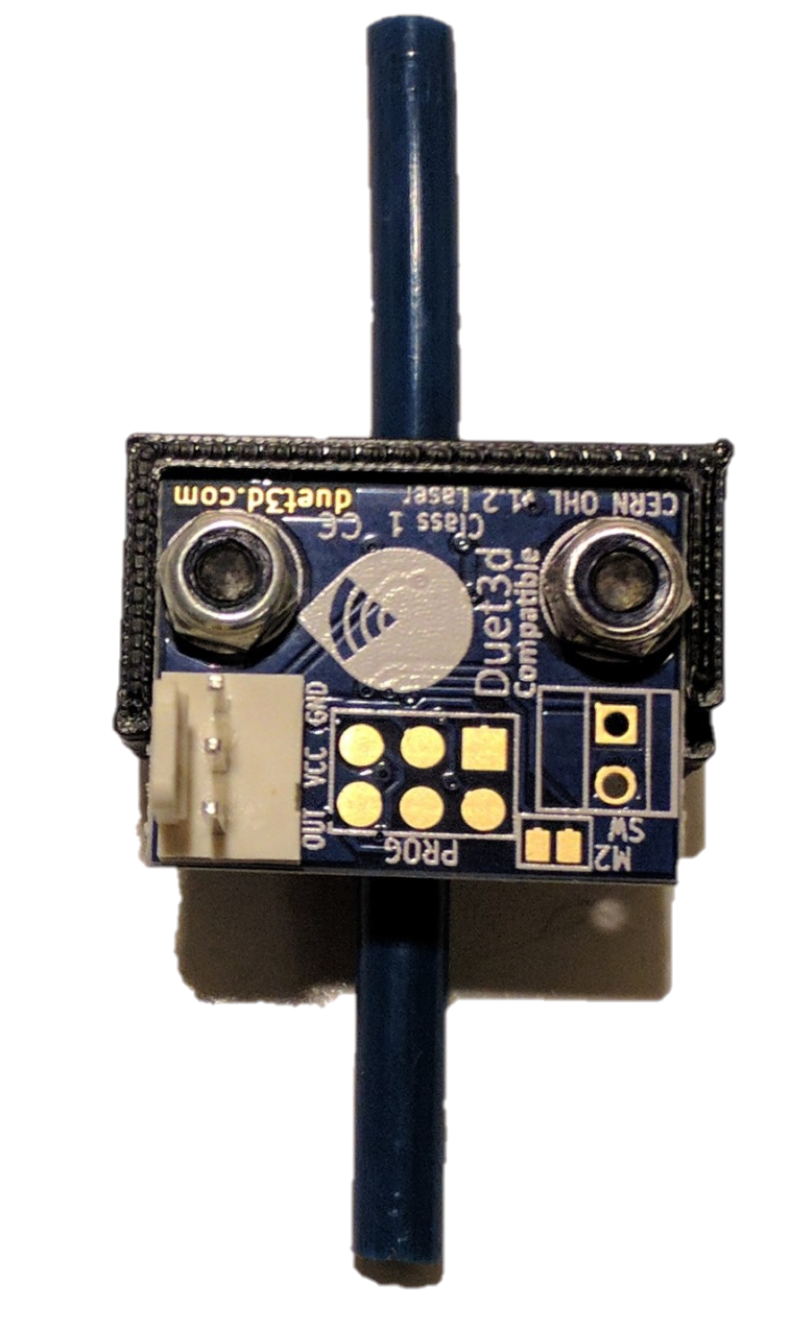
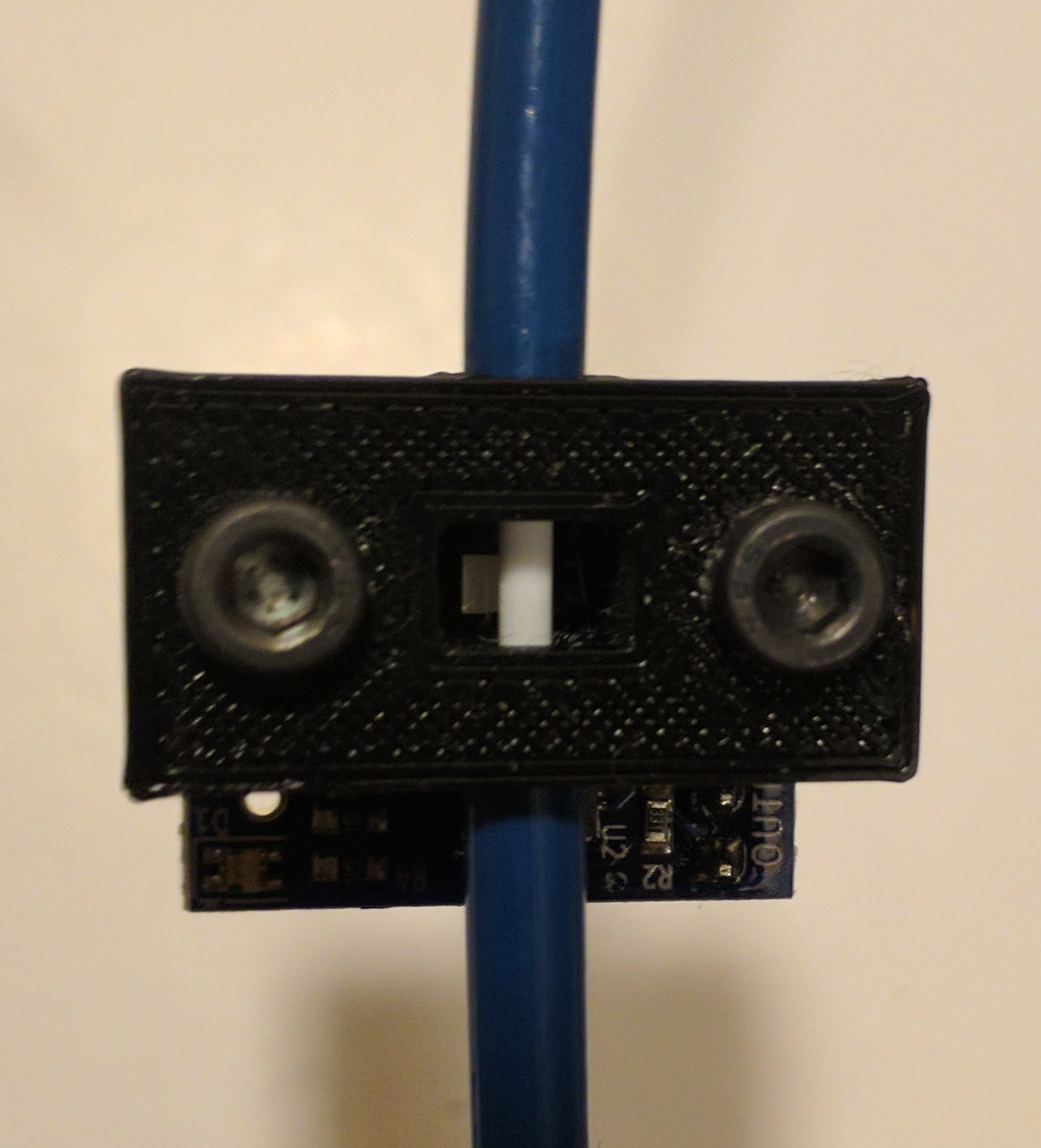
- Remove any stringing in the rectangular aperture in the top plate.
- Put the two screws through the top of the top plate. Turn the top plate with screws in it upside down so that the grooves for the PTFE tube are uppermost. Lay the base plate on top, with the grooves on the underside and the PCB cutout on top. Place the PCB over the screws, with the connectors uppermost, so that the PCB fits in the cutout for it. Add the optional washers and nuts and secure them loosely.
- Insert the two pieces of PTFE tubing into the two holes formed by the grooves in the two plates. They must not protrude at all into the rectangular opening. Tighten the nuts to secure them in place.
¶ Mounting
The Laser Filament Monitor should be mounted in such a way as to avoid dust settling on the optical sensor, which is on the component side of the PCB (the opposite side to the connectors). Do not mount it with the optical sensor facing up and connectors facing down. If you mount it with the filament path horizontal, mount it with the connectors uppermost if possible. If you mount it with the filament path vertical, orient it with the connectors at the bottom so that closed end of the housing is at the top.
Caution! Check that the printed part that the sensor PCB will sit in has no blobs or other blemishes that would cause a bending force to be applied to the PCB when the screws are tightened.
It does not matter which end of the filament monitor you use as the filament inlet and which end as the outlet, direction is set as part of configuration and tuning of the monitor.
The distance between the filament monitor outlet and the extruder drive inlet should be kept short and the filament must be constrained by PTFE tubing over this distance, so that when the filament reverses its movement direction due to retraction, the retracted filament is forced to reverse through the filament monitor.
If you need to place anything close to or on top of the rectangular aperture in the top plate of the filament monitor, it must be matt black. One option is to replace the top plate (see the Hardware section) by a deeper version that is closed at the top.
¶ Wiring
¶ Warnings
- The optical sensor on the filament monitor PCB is delicate! Take great care not to damage it or to touch it. Do not put the filament monitor PCB component-side down on any surface. Damage to the optical sensor is not covered by the warranty.
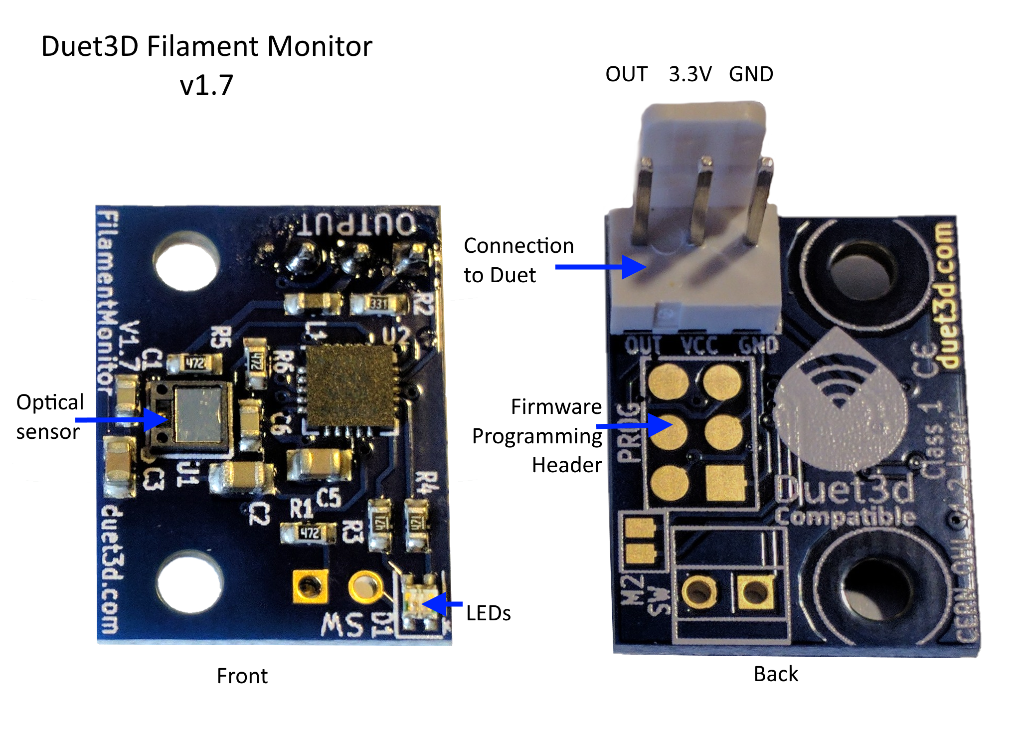
- The Duet3D Laser Filament Monitor is designed to be powered with 3.3v only. If you supply 5V power to it, you will destroy the optical sensor.

- The sensor is a Class 1 Laser device. Under normal conditions, the laser beam is always below the IEC/EN 60825-1:2014 maximum permitted output level of 716uW according to the manufacturer of the optical sensor; nevertheless we advise against looking into the beam when the filament monitor is powered. You should most definitely not look at the sensor through magnification when it is operating. The laser beam is invisible infra red, therefore your eye blink reflex will not protect you!
¶ Connecting and configuration
For connecting, firmware configuration, commissioning and troubleshooting, see Connecting and configuring filament-out sensors.
¶ Housing variations
The laser sensor shows different performance based on the type of filament being used, and potentially some other variables such as the material the housing is printed from and ambient infrared light. See this forum thread for examples from testing.
Other than determining which filaments work well and which ones work less well, areas for experimentation to determine what improvements can be made relate to housing design. Some of these options have been added to an extended version of the housing design referenced above, available here.
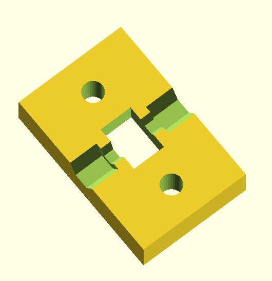
This part holds the filament guide PTFE tubing against the matching part on the sensor. Potential improvements:
- The laser light that does not reflect off the filament reflects off parts of both blocks so it might work better if printed with something that absorbs IR radiation of ~850nm
- Having a divergent light path to reduce stray reflections back to the sensor might help, See the "divergeAmount" variable in the OpenSCAD desing on youmagine:
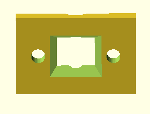
This image shows the divergence exaggerated to show the effect
- Closing the back of the filament block could prevent ambient IR from interfering with the sensor, alternatively it could increase unwanted reflections. Use the "closedTop" option in the OpenSCAD file to change this. A conical or pyramid-shaped closure might work even better, by containing light from the laser within the closure instead of reflecting it towards the sensor.
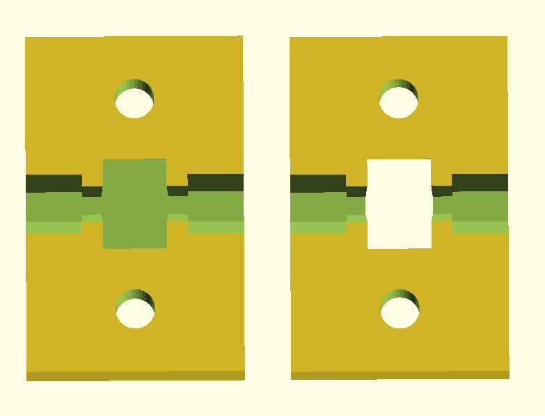

This part holds the filament path guides, along with the filament block. it also holds the sensor PCB. Potential areas for improvement:
- The laser light that does not reflect off the filament reflects off parts of both blocks so it might work better if printed with something that absorbs IR.
- Having a divergent light path to reduce stray reflections back to the sensor might help, See the "divergeAmount" variable in the OpenSCAD design on youmagine. The flight path starts in the sensor block and the ends in the filament block so this variable affects both piece.
- Changing the distance between the filament and the sensor changes the error level in the reading. Preliminary resting showed that ~9mm worked well for quite a few filaments. It may be that different filaments work better with different distances. To change this use the "filamentHeight" variable in the OpenSCAD file:

For 2.85mm filament, we suggest you use 3mm ID PTFE tubing (not 1/8") and adjust the groove sizes in the base and top plates to accommodate the larger tubing. Also increase the thickness of the base plate by 0.6mm to keep the distance between the optical sensor and the outside of the filament the same.
Some people have had success using the laser filament monitor to read a bearing or steel ball which the filament is turning. See this form thread for an example.
¶ Technical details
¶ Communications Protocol
The filament monitor sends 16-bit words to the Duet. When the filament position is changing, a filament position word is sent every 40ms. When the data isn't changing, alternating filament position words and status words are sent every 500ms.
The 16 bits are sent using a self-clocking protocol as follows. The nominal bit time is 1ms but the Duet firmware allows a reasonable tolerance because the filament monitor clock source is the internal R-C oscillator in the microcontroller, so its speed is somewhat variable.
Idle state: the line must be be at 0 for at least 8 bit times
Start bits: 1 followed by 0
Data bits 15, 14, 13, 12
Stuffing bit (inverse of bit 12)
Data bits 11,10,9,8
Stuffing bit (inverse of bit 8)
Data bits 7,6,5,4
Stuffing bit (inverse of bit 4)
Data bits 3,2,1,0
Stuffing bit (inverse of bit 0)
After the last stuffing bit, the line returns to 0 until the next start bit.
The meanings of the 16-bit words is as follows. P is the parity bit, adjusted so that the total number of set bits in the word is even,
| Word type | Format | Notes |
|---|---|---|
| v1 Data word | P00S 00pp pppp pppp | S = switch open, pppppppppp = 10-bit filament position (50 counts/mm) |
| v2 Data word | P00S 1ppp pppp pppp | S = switch open, ppppppppppp = 11-bit filament position (100 counts/mm) |
| v1 Error word | P010 0000 0000 0000 | |
| v2 Error word | P010 0000 0000 eeee | eeee = error code, will not be zero |
| v1 Quality word | P10s ssss bbbb bbbb | sssss = shutter, bbbbbbbb = brightness |
| v2 Version word | P110 0000 vvvv vvvv | vvvvvvvv = sensor/firmware version, at least 2 |
| v2 Image quality wor | P110 0001 qqqq qqqq | qqqqqqqq = image quality |
| v2 Brightness word | P110 0010 bbbb bbbb | bbbbbbbb = brightness |
| v2 Shutter word | P110 0011 ssss ssss | ssssssss = shutter |
¶ Revision history
This uses the PAT 9130 laser sensor and has some minor firmware tweaks to improve the communication protocol and distinguish between the revisions.
The housing is slightly different for this board, although they are the same size. See the housing section for links to the new housing.
Firmware 2.03 or later is required to use the version 2.0 sensor and report the correct values.
This uses the PAT 9125 laser sensor.