¶ Overview
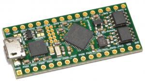
The Sammy-C21 from chip45.com is a low-cost development board based on the SAMC21G18A microcontroller, which is the same microcontroller used in the Tool Board and in other CAN-connected Duet3D products. Its small size and integrated CAN transceivers make it suitable for use as a basis for building custom add-ons to Duet3D systems.
The Sammy-C21 can be purchased from the manufacturer chip45.com (Germany) and from Filastruder (US). Boards supplied by Filastruder should have the Duet3D bootloader pre-installed, and you can have the Duet3D CAN bootloader pre-installed as an option when ordering direct from chip45.
Depending on what development you intend to do, you may also need the following:
- The optional pin header kit from chip45. This includes 2.54mm pitch headers for the IO pins (allowing you to plug the device into a standard solderless breadboard) and a 10-pin 1.27mm pitch header for connecting an Atmel ICE.
- Atmel ICE Basic. This is a tool for programming and debugging systems using Atmel/Microchip processors. This can be obtained from the usual electronic components distributors (Farnell, RS, Digikey, Mouser, Newark etc.) as well as from chip45.com.
¶ Connecting the Sammy-C21 to a Duet 3 system
The Sammy-C21 has dual CAN ports, labelled CAN0 and CAN1. The firmware and bootloader that we provide are written to use CAN0.

Like the Duet3D tool board, the Sammy-C21 has no facility for on-board termination of the CAN bus. It may be connected as a stub on the CAN bus if the stub wire is short, alternatively you can run the CAN bus to the Sammy-C21 and then on to the next device.
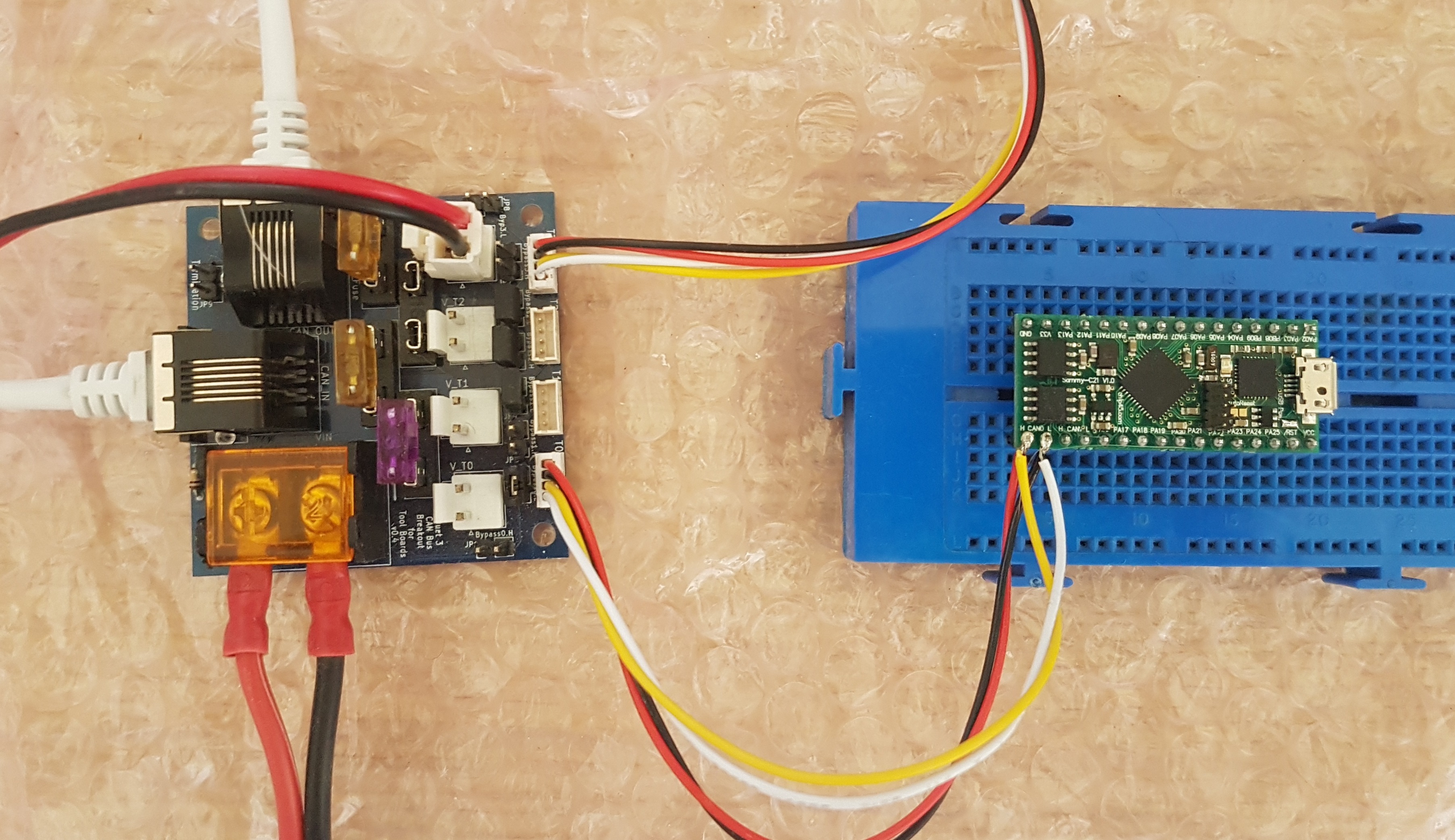
If your system already includes a Duet3D tool distribution board then a convenient way to connect a Sammy-C21 is as you would connect a tool, using a 4-way cable (ideally two twisted pairs) between the Sammy-C21 and the tool distribution board as shown here.
¶ Powering the Sammy-C21
The easiest way to power the Sammy-C21 is to bridge pads J100 and then apply power via the micro USB socket. Alternatively, leave J100 not bridged and apply 5V power to the VCC pin.
Normally, the SAMC21 processor runs from 3.3V so all the I/O signals have 3.3V signal levels. If you need 5V signal levels, connect V33 to VCC so that the SAMC21 processor runs from 5V.
¶ Programming the bootloader
If you did not order the Sammy-C21 with the Duet3D bootloader pre-installed, and you wish to update its firmware over CAN, then you will need to install the bootloader using the Atmel ICE and Atmel Studio 7. The bootloader project can be found on Github here. Use this procedure to install the bootloader:
-
Connect the Atmel ICE to the Sammy-C21 via the 10-pin connector and to your PC via USB.
-
Load Atmel Studio 7 (requires Windows) on your PC. Select Tools/Device programming, select the Atmel ICE tool, and select device ATSAMC21G18A.
-
If your Sammy-C21 is not configured to use USB power, apply VCC power to it.
-
Click the Read button under Device Signature. It should report the device ID and the target voltage (3.3V, or 5V if you have connected V33 and VCC together).
-
Under Memories, check that Erase Flash before Programming and Verify Flash after programming are checked.
-
In the Flash box, browse to and select the Duet3Bootloader-SAMMYC21.elf file, then press Program
-
If verification fails, this is normally because the bootloader area is protected. To remove the bootloader protection, first click Erase Now. Then select the Fuses tab. Scroll down to USER_WORD_0.NVMCTRL_BOOTPROT, and set the value to 0. Click Program. Then return to the Memory page and try to program the bootloader again. Note, this will not work if the Sammy-C21 is connected via CAN to a running Duet 3 system, because the bootloader will immediately load firmware, which will immediately reinstate the bootloader protection.
¶ Loading firmware
With the bootloader installed, the Sammy-C21 will request firmware file Duet3Firmware_SAMMYC21.bin from the main board over the CAN bus. We suggest that you install our sample firmware binary initially to check that everything is working, before making your own modifications. You can find our sample firmware in this project on Github. When the firmware is running and CAN communication with the Duet 3 main board is established, the green LED on the SammyC21 should blink in sync with the STATUS LED on the Duet 3 main board (labelled DIAG on older Duets).
If firmware is installed but unresponsive, you can force the bootloader to fetch new firmware by tying pin PB09 to ground while you power up the Sammy-C21.
¶ Debugging your own firmware
Firmware is easier to debug if you load it directly using the Atmel ICE instead of via the bootloader. To do this, you will have to build your firmware to run at address 0x00000000 instead of 0x00004000. The SammyC21-Debug build configuration of the Duet3Expansion project is built this way. If you have previously installed firmware via the bootloader, you will need to remove bootloader protection, as described in the bootloader installation instructions above.
¶ Features of the standard firmware binary
- The default CAN address is 124. It can be changed in the usual way using the M952 command.
- M115, M122, M997 with the appropriate B parameter can be used to query and update the board in the usual way.
- A single external driver can be connected. Connect STEP- to PA11, DIR- to PA10, and ENA- to PA09. Connect STEP+, DIR+ and ENA+ to the V33 pin. If your external drivers need 5V, see earlier for how to change the I/O signal level to 5V.
- Messages written using the debugPrintf() function will be sent to the USB port. Use YAT or similar to see them.
- The following ports are available:
| Name | Digital input? | Analog input? | Output? | PWM output? | Notes |
|---|---|---|---|---|---|
| pa04 | yes | yes | yes | yes | |
| pa05 | yes | yes | yes | no | |
| pa06 | yes | yes | yes | yes | |
| pa07 | yes | yes | yes | no | |
| pa08 | no | yes | yes | no | |
| pa12 | yes | no | yes | yes | |
| pa13 | yes | no | yes | no | Reserved for accelerometer interrupt in firmware 3.3 and later |
| pa16 | yes | no | yes | no | Reserved for SPI sensor support if SUPPORT_SPI_SENSORS is set |
| pa17 | yes | no | yes | no | Reserved for SPI sensor support if SUPPORT_SPI_SENSORS is set |
| pa18 | yes | no | yes | no | Reserved for SPI sensor support if SUPPORT_SPI_SENSORS is set |
| pa19 | yes | no | yes | yes | |
| pa20 | no | no | yes | no | |
| pa21 | no | no | yes | no | Reserved for LDC1612 interrupt in firmnware 3.5 and later |
| pa22 | no | no | yes | no | Reserved for I2C SDA signal in firmware 3.3 and later |
| pa23 | no | no | yes | yes | Reserved for I2C SCL signal in firmware 3.3 and later |
| pa24 | no | no | yes | no | |
| pa25 | no | no | yes | no | |
| pb08 | yes | no | yes | no | |
| button1 | yes | no | no | no | Button connected to PB09 |
"button1" is for a normally-open push button connected between PB09 and ground.
¶ Duet3D Firmware source code for SammyC21
Bootloader: https://github.com/Duet3D/Duet3Bootloader. This occupies the first 16Kb of flash memory.
Main firmware: https://github.com/Duet3D/Duet3Expansion. The standard build configuration is intended to be installed by the bootloader, so it it configured to start 16K above the base of flash memory. The Debug build is intended to be loaded directly by the Atmel ICE, so it it loaded at the start of flash memory.