¶ Introduction
This is a DIY project to interface a popular style of CNC pendant to the PanelDue port of a Duet 3 or Duet 2 WiFi/Ethernet/Maestro. It allows you to jog the axes of the Duet by holding down the Enable button and turning the wheel. The rotary switches select which axis you jog and how much it moves for a given movement of the handwheel.
¶ Parts needed
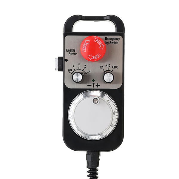
- One wired CNC pendant similar to the image above. These are available in 4-axis versions (illustrated) and 6 axis versions (with the axis selector switch having additional position 5 and 6). Either will work.
- One Arduino Pro Micro (5V/16MHz version), Arduino Micro or Arduino Nano (Pro Micro preferred)
Note: the Pro Micro is not an official Arduino board. It was developed by Sparkfun. Clones are available from many sources. It is supported by the Arduino IDE. - One 10K wire-ended resistor (optional if the pendant will be used only with a Duet 3 board)
- One 6.8K wire-ended resistor (optional if the pendant will be used only with a Duet 3 board)
- 4-core unshielded cable, as long as you want. You could instead re-use the 18- or 20-core cable that comes with the pendant, but the 4-core cable is thinner. If you do not need the PanelDue pass through feature, then 3-core cable is sufficient.
- 4-way (for Duet 2) or 5-way (for Duet 3) Molex KK connector shell and crimp pins to plug into the PanelDue port of the Duet (you should have received some of these with your Duet)
- Small cable ties
¶ Tools needed
- Soldering iron + solder
- Wire cutters and strippers
- No. 2 Phillips screwdriver
- Crimp tool suitable for Molex KK connectors (e.g. Engineer PA21)
- Micro USB cable (for programming)
- Wooden dowel and heat gun (if you want to curl the 4-core cable)
¶ Programming the Arduino Pro Micro
- Install Arduino IDE on your PC. The version probably doesn't matter; we have used versions 1.8.1 and 2.3.6 successfully.
- Create a new sketch called CNC-pendant.
- In a web browser, go to https://github.com/Duet3D/CNC-Pendant-Firmware.
- If using RepRapFirmware 3.5.x or later, select the crc16 branch. If using RepRapFirmware 3.4.x or earlier, use the main branch.
- Download all the files from the /src folder and put them in your sketch folder, overwriting the CNC-pendant.ino file already there.
- Select board type Sparkfun Arduino Micro.
- Select processor type 5V/16MHz (this is very important!)
- Connect the Arduino to your PC via USB, select the correct COM port, and program the sketch in it.
For wiring differences and hardware changes needed if using an Arduino Micro or Nano, see the comments at the start of the CNC-pendant.ino file.
Note: If you experience issues with skipped steps when using the encoder, a possible fix has been posted on the Duet forum by user morgoth90 here: https://forum.duet3d.com/topic/36798/cnc-pendant-encoder-skipping-step. They wrote: "After a few fast encoder rotations the detected pulses disalign resulting in two stray pulses after each detected movement. This behaviour is probably caused by some missed pulse but as result will ignore the first movement in the opposite direction. After some tests I fixed the issue rewriting the encoder code using the Arduino Encoder library." If you want to implement this change, replace the RotaryEncoder.cpp and RotaryEncoder.h files in the CNC-pendant sketch with those from the forum thread. Feedback welcome.
¶ Wiring
¶ Wiring diagram
Click for larger version
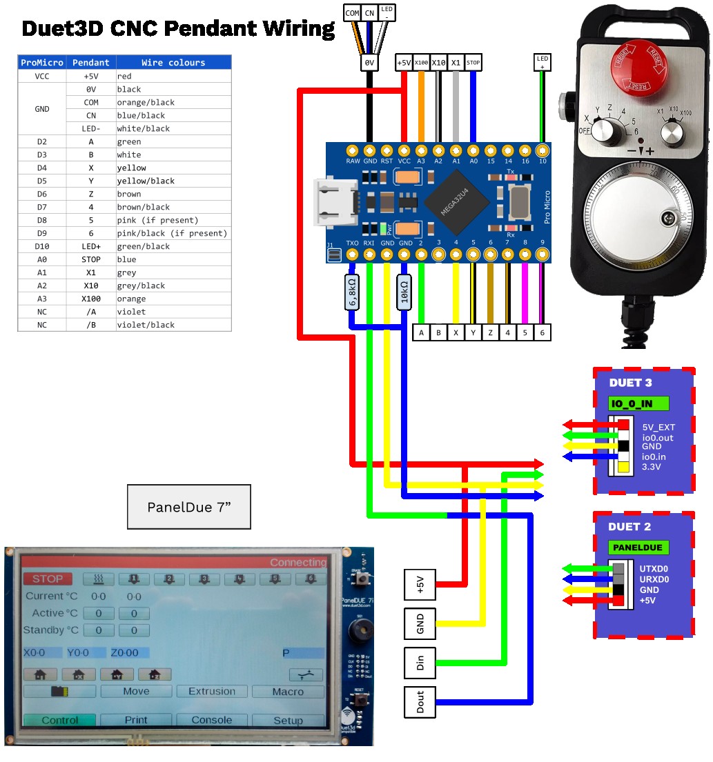
Thanks to forum user jeffouille for the diagram.
¶ Cable
If you are replacing the 18-or 20-core cable supplied with the pendant by 3- or 4-core cable, cut the 3- or 4-core cable to length, wind it around the wooden dowel and use the heat gun to set the curls.
Remove the back of the pendant and cut the 18- or 20-core cable close to the body of the pendant, making sure that you leave enough length for the individual wires to reach the Arduino, which will be installed in the top of the pendant. Remove the cut cable from the cable gland and feed the 4-core cable though it instead. Use tape or heatshrink on the outside of the 4-core cable to make it big enough for the cable gland to grip.
¶ Pendant to Arduino Pro Micro wiring
The cut ends of the original 18- or 20-core cable, and the cores of the 4-core cable, must be connected to the Arduino Pro Micro as listed below.
| Pro Micro | Pendant | Wire colours |
|---|---|---|
| VCC | +5V | red |
| GND | 0V | black |
| COM | orange/black | |
| CN | blue/black | |
| LED- | white/black | |
| D2 | A | green |
| D3 | B | white |
| D4 | X | yellow |
| D5 | Y | yellow/black |
| D6 | Z | brown |
| D7 | 4 | brown/black |
| D8 | 5 | pink (if present) |
| D9 | 6 | pink/black (if present) |
| D10 | LED+ | green/black |
| A0 | STOP | blue |
| A1 | X1 | grey |
| A2 | X10 | grey/black |
| A3 | X100 | orange |
| NC | /A | violet |
| /B | violet/black |
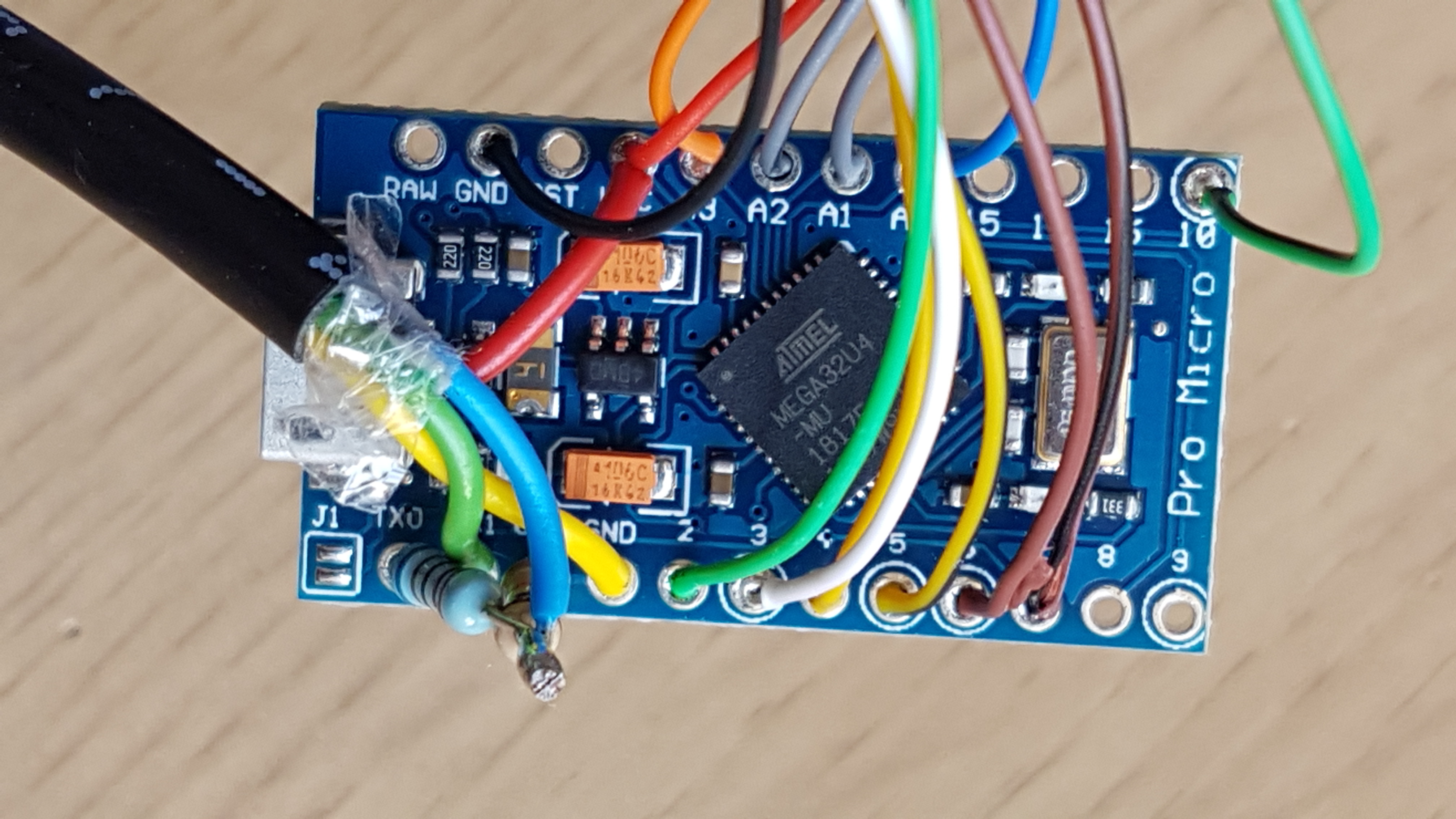
As there are several wires that need to be connected to ground, it's easiest if you connect them together at the ground (black) terminal of the rotary encoder, then run a single wire from there to Arduino GND. That way you don't need to connect more than one wire to each pad of the Arduino, except that you need to connect both +5V from the 4-core cable and +5V for the encoder to the VCC terminal.
¶ Arduino Pro Micro to Duet wiring
Wire the Arduino Pro Micro to the Duet 3 IO_0 connector or Duet 2 PanelDue connector. You can use a 3-core cable if you don't plan on connecting a PanelDue, or 4-core cable if you do.
| Pro Micro | Duet | Wire colour |
|---|---|---|
| VCC | +5V | red |
| GND | GND | yellow |
| TXO | Through 6K8 resistor to IO_0_IN (Duet 3) or URXD0 (Duet 2) or direct to Duet 3 IO0_IN | blue, from resistor junction to Duet |
| GND | Through 10K resistor to IO_0_IN (Duet 3) or URXD0 (Duet 2) or omit for Duet 3 |
If the pendant will be used only with Duet 3 electronics then you can dispense with the two resistors and connect TX0 directly to the IO0_IN pin 0f the Duet 3.
If you do not intend to use a PanelDue at the same time as the pendant, it's best to leave the green wire of the 4-core cable (the one that would be connected to DOUT on the PanelDue) not connected to the Arduino RX0 pin, otherwise it might pick up noise.
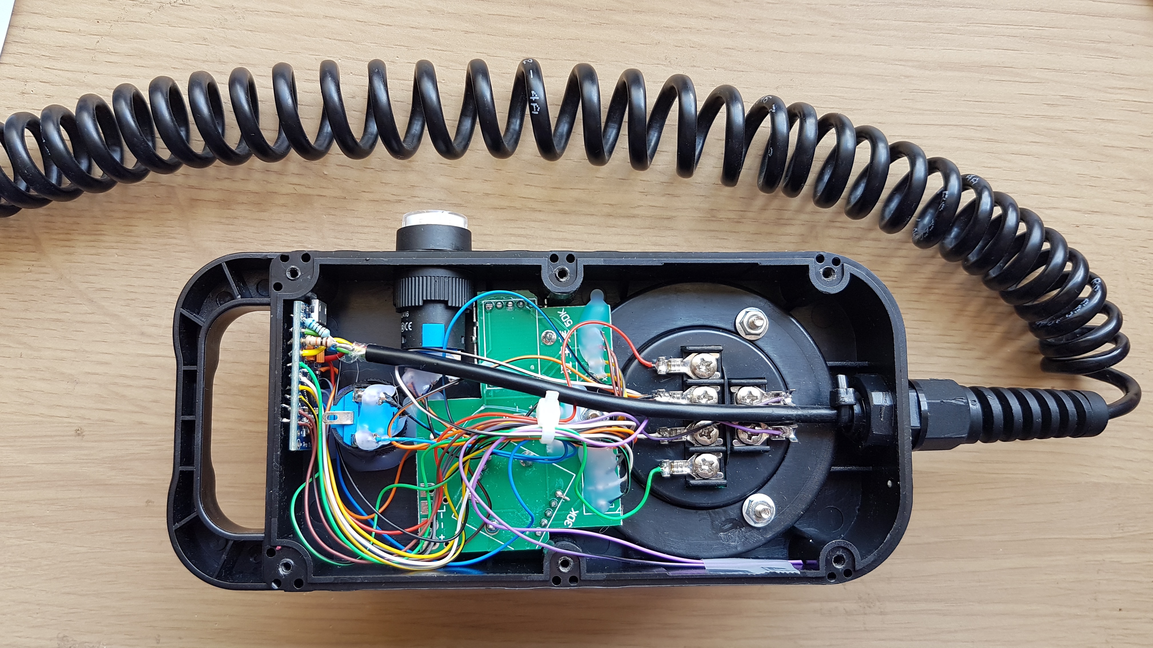
The Arduino can then be tucked inside the top of the pendant as shown above.
Before refitting the back of the pendant, put some Kapton tape or insulating tape over the top two magnets, to prevent them from possibly shorting out connections on the Arduino.
¶ PanelDue pass through
To connect a PanelDue as well, the Arduino Pro Micro passes the PanelDue commands through to the Duet. The PanelDue can be connected at either end of the cable, i.e. close to the Arduino Pro Micro if you wanted to have a combined Pendant with PanelDue display, or at the Duet end if the PanelDue is mounted to the machine and the Pendant is used remotely.
| PanelDue | Pro Micro / Duet | Wire colour |
|---|---|---|
| +5V | +5V/VCC on Arduino or Duet | red |
| GND | GND on Arduino or Duet | yellow |
| DIN | Duet IO_0_OUT (Duet 3) or UTXD0 (Duet 2) | green |
| DOUT | Arduino Pro Micro RXI | blue wire of PanelDue cable to green wire of pendant cable |
The DOUT signal from the PanelDue (which is usually the blue wire in a 4-core cable) must be connected to the RXI pin of the Arduino in the pendant (the green wire in the 4-core pendant cable is used in the wiring list). Connect the blue wire from PanelDue to the green wire of the pendant. Connect the DIN (green) PanelDue wire to the IO_0_OUT pin of the IO_0 connector (Duet 3), or the UTXD0 pin of the PanelDue connector (Duet 2). The +5V pin on the Duet connector goes to the +5V (red) wire of both the pendant and the PanelDue, likewise the ground connection goes to the yellow wires of both.
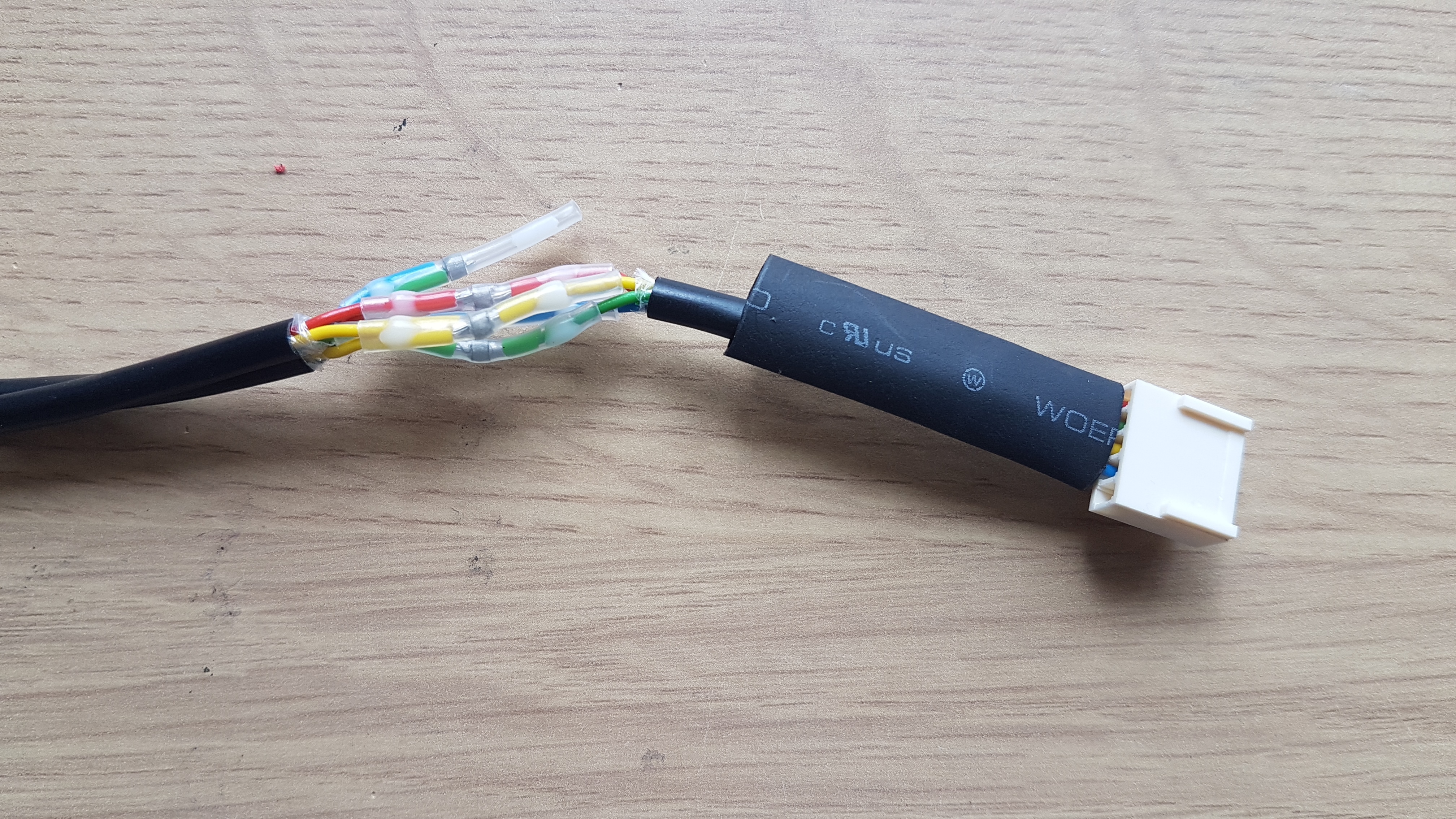
I used solder sleeves to connect the PanelDue and pendant cables to a short length of 4-core cable that plugs into the Duet, as shown here before I shrunk the heatshrink over the joints.
¶ Support requests
Please use the forum for support requests.