¶ Checking connected stepper motors
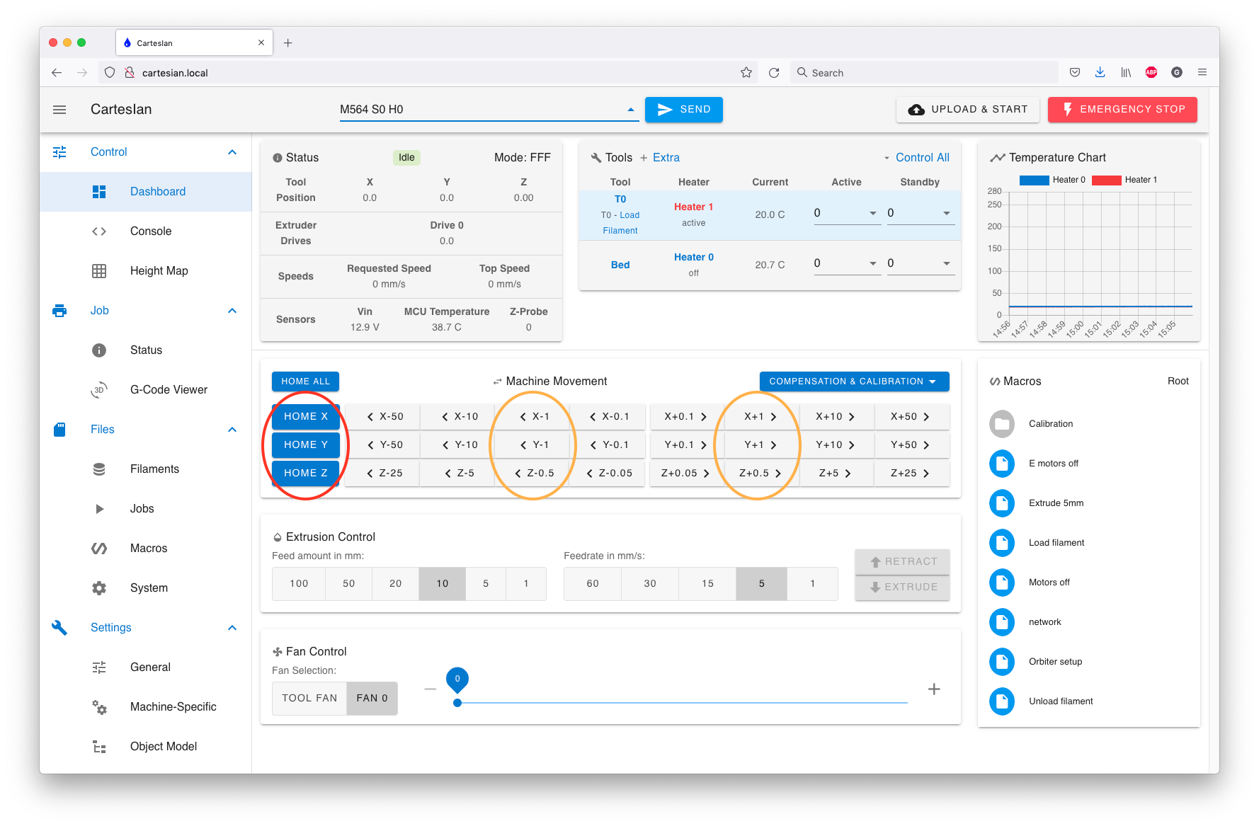
Before conducting this step, temporarily allow axis movement without homing by navigating to the G Code console in Duet Web Control (DWC) and entering:
M564 S0 H0
NOTE:
M564 S0 H0may not work if your machine's kinematics use non-linear axes, eg Delta, Scara or Polar, because until RRF knows where the effector/head is, it has no idea how to move the motors to achieve a desired position. UseG91thenG1 H2moves for testing (see 'Checking movement direction' below), or sendG92 X0 Y0 Z0to set an approximate initial position.
For machines with cartesian and CoreXY kinematics, navigate back to the Machine Control page. At this time, we will check the operation of our stepper motors.
Move each stepper motor, individually, 1 mm in each direction.
Note that a stepper can't be moved before homing, unless the M564 command is used to override this safety default.
¶ Checking movement direction
To test a motor individually, first position the carriage(s) well away for the endstops. Then send G91 to select relative coordinates. Then use G1 H2 moves to test motors (use G1 S2 moves for firmware RRF_2.01 and earlier). Here is an example:
| Command | What to expect (Cartesian) | What to expect (CoreXY) | What to expect (Delta) | What to expect (Scara) |
|---|---|---|---|---|
| G91 | ||||
| G1 H2 X10 F100 | Print head moves 10mm in the +X direction | Print head moves 5mm in the +X direction and 5mm in the +Y direction | X carriage moves up 10mm | Proximal arm moves anticlockwise 10 degrees |
| G1 H2 X-10 | Print head moves 10mm in the -X direction | Print head moves 5mm in the -X direction and 5mm in the -Y direction | X carriage moves down 10mm | Proximal arm moves clockwise 10 degrees |
| G1 H2 Y10 | Print head moves (relative to bed, if bed moves) 10mm in the +Y direction | Print head moves 5mm in the +X direction and 5mm in the -Y direction | Y carriage moves up 10mm | Distal arm moves anticlockwise 10 degrees |
| G1 H2 Y-10 | Print head moves (relative to bed, if bed moves) 10mm in the -Y direction | Print head moves 5mm in the -X direction and 5mm in the +Y direction | Y carriage moves down 10mm | Distal arm moves clockwise 10 degrees |
| G1 H2 Z10 | Distance between bed and nozzle increases 10mm in the Z direction | Distance between bed and nozzle increases 10mm in the Z direction | Z carriage moves up 10mm | Distance between bed and nozzle increases 10mm in the Z direction |
| G1 H2 Z-10 | Distance between bed and nozzle decreases 10mm in the Z direction | Distance between bed and nozzle decreases 10mm in the Z direction | Z carriage moves down 10mm | Distance between bed and nozzle decreases 10mm in the Z direction |
In this example the move uses a specified feed rate of 100mm/min in the G1 H2 X10 command, so the 10mm moves should each complete in 6 seconds.
If any of the motors moves the wrong way, change the direction by editing the appropriate M569 command in config,g. Flip the motor direction for a specific axis by changing S1 to S0 or vice versa. For example, if the Y axis moves the wrong way and there is a M569 P1 S1 command in config.g, change S1 to S0 in that command.
¶ Testing extruder motor movement
If you wish to test your extruder motor movement, without connecting or heating up a heater, and/or with no filament loaded, define a tool that uses just the extruder motor. e.g. send:
M563 P0 D0
M563 creates tool T0 using the first extruder motor defined by your M584 command in config.g. For example, if you have M584 X0 Y1 Z2 E3:4 in config.g, D0 is the E0 motor connection (driver 3) on Duet 2 WiFi, D1 is E1 (driver 4). On Duet 3, D0 is DRIVER_3 and D1 is DRIVER_4.
To enable the extruder motor and move it, send:
T0
G1 E10 F60
The motor should extrude 10mm of filament at 1mm/s. Reset your Duet to revert your tools to the config.g settings before testing heaters!
