¶ 5 Bar Parallel Scara Printer
This printer type uses two rotational actuators to rotate the arms and one linear actuator for the Z movement. Parallel kinematics are told to have good precision due to its closed loop kinematics. Another advantage is that the actuators are stationary.
The name 5 bar origins from one bar between the actuators (mostly implicit by the frame) and two arms each left and right.
¶ Construction and Naming
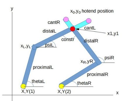
The names of the image are used in this documentation and in the firmware.
The red dot is the hotend position, the yellow dots represent the actuators/steppers.
At top are optional cantilevered arms with hotend positions at the end.
The positions of the actuators are defined by M669 X and Y parameters.
proximalL, distalL are the left arms in mm, proximalR and distalR the right ones. theta and psi left (L) and right (R) are degrees measured from the x axis. The optional cantilevered arm of distalL is of length cantL, for distalR it is cantR.
constr is a constraint angle: if the angle is too flat, the SCARA cannot be moved (singularity). If it is too small, the x0,y0 position becomes undefined.
x0,y0 is the hotend point, xL,yL and xR,yR the left and right hinges.
¶ Working Modes
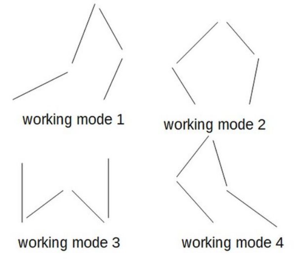
A point x0, y0 can be accessed with up to 4 different constellations for the proximal and distal arms. Every arm pair proximal + distal can be bent "inside" and "outside". The 4 possibilities are called working modes. The printer has to stay in one working mode. Supported modes are 1, 2 and 4, default being 1.
Care must be taken to avoid areas called singularity, which are unprintable areas because arm angles are too flat or small and the movement is undefined.
¶ Print area, depending on working mode
The print area can be tested in GeoGebra: EUurHEUE (untested and no warranty)
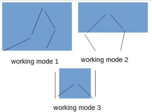
The print area depends on the arms lengths, the distance between the Actuators and the constraints. Roughly, the print area looks like this (mode 4 is mirrored to mode 1 by y axis):
¶ M669 configuration
Geometry settings are defined with M669, analoguous to the Scara setup. Z axis and stepper properties are defined like a Cartesian printer. K9 is the printer type mode.
Xnnn:mmm and Ynnn:mmm X and Y coordinates of the left and right proximal actuator axes. E.g. X0:100.5 Y0:0 means 100.5 apart and both on the y axis.
Lnnn working mode: 0, 1, 2, 3 or 4, see image above. Default is L1. Supported modes so far are modes 1, 2 and 4.
Pnnn:mmm proximal arm lengths: nnn is left and mmm is right proximal in mm. Can be fractions of mm, e.g. P300.5:299.8. The lengths are from the middle of one joint to the other one.
Dnnn:mmm[:ppp:qqq] distal arm lengths: nnn is left distal arm, mmm the right distal arm in mm, fractions are possible. E. g. D200:230.5. Lengths is measured from middle of joints. The optional parameters p and q see below for cantilevered arm. Currently, all 4 parameters must be set, so with uncantilevered hotends set :0:0 as parameters 3 and 4.
Bnnn:mmm defines the degrees of the homing end positions homingAngleL and R in respect to the x axis. The setting must be valid in respect to print area and other constraints. The values can be fractions of degrees. For workmode 1, default is B20:10, for workmode 2 it is B110:20, for workmode 4 it is B110:100
Annn:mmm:ppp:qqq:rrr:sss nnn is the minimum angle between the distal arms (constr in the first image) in degrees, mmm the maximum. ppp:qqq is the minimum and maximum angle between proximal and distal arms on the left. rrr:sss between proximl and distal on right. The mechanical construction might set limits. Default is A15:165:0:360:0:360
Znnn:mmm:ppp:qqq optional to define the print area as rectangle. Z0:0:500:200 means from 0,0 to 500,200. The user is responsible to define a reachable area.
comment on Z: *) Meant: if the printer moves from A to B, it may not move through an area where the movement is not possible in the given working mode.
Snnn Maximum segments per second (optional).
Tnnn Minimum segment length (optional).
With exception of K and L, all parameter values can include decimal parts.
Cnnn:mmm:ppp:qqq is the minimal and maximal angle left and right of the actuators. C10:100:15:200 means the left stepper can have angle between 10 and 100 degree, the right one between 15 and 200. Default is C10:170:10:170. The angles may be negative. Min and max angles are not allowed to overlap, e.g. -90 to maximal 269, to ensure inverse kinem.
¶ M92 configuration
For precision, it is preferable to use a gear at the actuator, between stepper and first hinge of the proximal arm. The higher the gear ratio, the better the precision (but slower maximum speed). A ratio between 1:5 and 1:30 is a good starting value.
The properties are set by the values of microstepping in M320 and setting the X and Y properties in M92:
M92 = microsteps / motordeg * bigpulleyteeth / stepperpulleyteeth
E.g. 128 microsteps, 1.8 degree steppers, 90 teeth at hinges, 20 teeth at steppers: M350 X128 Y128 ... and M92 should be 128/1.8*90/20=320, results in M92 X320 Y320 ...
Example 2: M350 X128 Y128 , 1.8 Stepper, 16 Stepper teeth, 300 mm diameter wheel: 128/1.8*471/16=2093, results in M92 X2093 Y2093...
¶ Example config file
M569 P0 S1 ; Drive 0 (X) goes forwards M569 P1 S1 ; Drive 1 (Y) goes forwards M569 P2 S1 ; Drive 2 (Z) goes forwards M569 P3 S1 ; Drive 3 (E0) goes forwards
M574 X1 Y1 Z0 S1 ; proximal L and R homing switches trigger when the arm is at M669 B positions and are active high
M669 K9 X0:100 Y0:0 P300:300 D300:300:0:0 ; arms are 300 mm long, actuators are 100 mm apart, other parameters take defaults. (Be aware, that D always needs 4 Parameters)
M203 X10000 Y10000 Z300 E3600 ; maximum speeds mm/minute M906 X800 Y800 Z800 E800 ; set motor currents (mA)
¶ Homing
The endstops are activated when the proximal arms are at a specific angle. The endstops can be activated from both sides of movement. Endstops trigger at different positions when approaching from left or right, so the homing strategy should approach from one side every time.
The endstops should be placed such that after homing the printer is in the correct working mode. Or after triggering the endstops, the arms are rotated with G1 H2 into positions of the correct working mode before normal operation.
When starting the printer, the axes shall be roughly near the endstops to avoid approaching singularities.
The endstops and M669 B parameter define the theta angles (proximal arm's angles). With e.g. M669 B90:90, when reaching both endstops, both steppers are at position 90 degree each for thetaL and thetaR.
¶ Stepper individual testing
Stepper can be rotated freely with G1 H2 g-code, e.g. with G91 G1 H2 X10 rotates the first actuator relatively by 10 degree in the counterclock direction. Endstops are ignored, be careful not to damage anything, start with low values and low speed (e.g. F100).
A stepper's current machinePos can be viewed by calling M114. The Count value lists the machinePos of the actuators, which is M92*degree, e.g. homing at 10 degree with an M92 value X540 results in 5400 as Count value.
¶ Calibration
steppers must have the correct direction set in the M569 g-code line (S0 or S1) and correct steps/degree setting with the M92 setting (see above).
The stepper position can be seen by calling M114: the Count values are the absolute stepper positions (machinePos in source). E.g. the homing position of the first actuator is the M92 value for X * homing angle.
The arm lengths must be measured from hinge middle start of the arm to hinge middle end of the arm.
The x and y position differences of the two proximal arms must be measured from the middle of the axes.
¶ Cantilevered arm 1
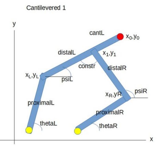
If the top joint shall not contain the hotend, a cantilevered construction can be used.
cantL is the prolongation of the left distal arm. Length is from middle joint to middle hotend.
M669 D is changed to Dnnn:mmm:ppp:0. ppp is set to cantL, qqq must be 0. Example: D300:300:100:0
¶ Cantilevered arm 2
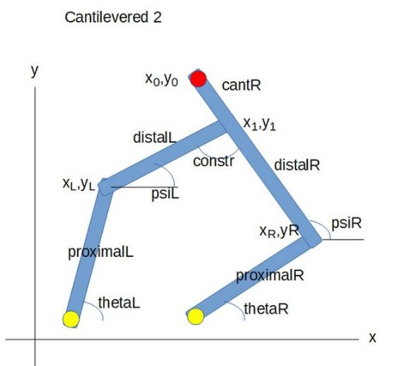
In the second cantilevered configuration, the right distal is prolongued by cantR.
Syntax of M669 is Dnnn:mmm:0:qqq, where qqq is the cantR length.
¶ Combined cantilevered
While printing, the normal and two cantilevered properties can be switched by applying the M669 command. This allows multiple hotends, if they are located on the left or right cantilever.
Placing hotends inside the distal arm maybe possible (by setting a negative cantilever value). It will be tested.
¶ Proximal distance 0
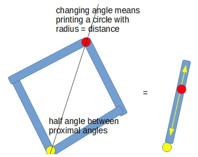
A Scara can be built setting proximalDistance to 0.
The two actuator axes are at the same x,y position. This can be achieved by stepper bottom-up and top-down, or by harmonic drives (using the hole in one drive to put through the other axis), or other means.
If the arms lengths are same, calculation is easy: the arms form a rhombus. The kinematics can be calculated by the middle angle and radius, see image.
Instead of two turning steppers, the Scara could be built with a turning stepper and a linear actuator which changes the radius.
¶ Working modes technically explained
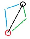
Image 1: If red is one of the XY actuators (stepper axis) and black the hotend, then the proximal and distal arm can be in the blue or green position. The same is true for the other actuator. Together there are 4 possibilities. Those are the 4 working modes.
Actuator 1 using green and actuator 2 using green also is working mode 1 e.g.
If calculating the inverse kinematics, i. e. calculating from the hotend position back to the actuators, the firmware has to know which of the 4 possibilities to take. The user tells the firmware with the M669 L1, L2, L3 or L4 parameter the working mode.

Image 2: changing working modes is only possible when the proximal + distal arms of an actuator are in line. *)Then an actuator rotation counterclockwise selects the blue mode, clockwise the green. The points of this situation is called singularity type 2 and is the print area limit also.
*) Being in line can also be, if the distal arm is 180 degree opposite direction to the proximal arm. It looks a bit strange.
Changing working mode while printing would mean to move the hotend to a position on singularity type 2, and then "choosing blue or green". But this extra move may corrupt a print process by the hotend move and the required time , and the move must be without extrusion. For this reasons, it's currently not implemented in the firmware.