This page is part of multiple pages about robot configuration and usage. Please choose the robot tag to see an overview.
¶ Introduction
Denavit-Hartenberg (DH) parameters are often used in robotics to describe the robot properties like axis orientations and arm lenghts.
Denavit-Hartenberg is shortened to DH in the following document. The 4 DH parameters are called theta, d, alpha and a. DOF stands for degrees of freedom.
The following images are based on this Youtube video
The following 6 axis robot is used to explain the DH parameters:
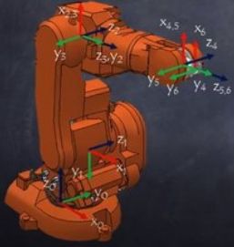
Please check Wikipedia for an introduction of DH. In brevity:
- coordination axes are used to describe where the robot actuators are placed
- the Z axis is the rotation axis for a rotational actuator and prismatic axis for a linear one
- the DH parameters describe 4 of the 6 degrees of freedom to transform one coordinate system to the next: Z translate and rotate, then X translate and rotate. Not all transformations are possible (Y translate and rotate).
- the DH parameters are defined in M669 A parameter.
¶ Parameters for setting configuration
work in progress
(moved vom configuring page)
DH based configuration can be used as starting point in the RobotViewer DWC plugin and converted to screw theory parameters.
- D"n:..." Denavit-Hartenberg (DH) parameters
¶ parameters (ex M669 D)
Dn define DH parameters and are numbered from 0 to maximum 9.
There is a separate document about DH parameters with examples. The DWC plugin RobotViewer shall help with configuration.
The standard usage is:
- every DH parameter set has one D... defintion with numbers 0 to 9
- after D, optional invert and number, there are 1, 4 or 6 parameters, all parts delimited with :
- D0 is optional the definition of the base. If the first axis is vertical starting in 0,0,0, D0 can be omitted
- D1 to D6 are DH parameters with actuators assigned (or less numbers for less actuators)
- D7 for tool. Offset values of the current selected tool G10 will be added
For less (more) actuators, less (more) D-s are used. The p (parallelogram 4 axis) has its own Dn and if it has values, they are added to the parallelogram angles.
The standard can be changed with the B parameter and Dn numbers can have holes, e.g. start by 1 without 0.
Every Dn contains three translates and three rotations by Z, Y, X axis in this order. The parameters are explained in detail on the DH Parameter documentation page.
Original set of DH parameters:
D"n:d:theta:a:alpha"
- the original DH definition define Z axis and X axis translate and rotate each, but no Y axis change
- n are unique integer numbers starting from 0
- d displacement in Z direction
- theta rotation by Z axis, added to the variable theta angle
- a is the shortest distance between Z and former Z axis. If alpha is 0, +-90 or +-180 degrees, the distance is the arm length
- alpha is the X axis rotation
- the internally used ytr and yrot values are set to 0.0 each
Extended set with addition Y parameters:
D"n:d:theta:ytr:yrot:a:alpha"
- values meaning as above
- additionally, ytr and yrot define displacement and rotation/translate around the Y axis
The two versions can be mixed, e. g. using the short version if ytr, yrot is 0.0 each.
D"!n:..."
Same as above, but inverts the transformation. Inverts rotations and translations. This is used for workpiece mode and explained in a world mode vs. workpiece mode chapter.
D"n:ztr|d|zrot|ytr|yrot|xtr|a|xrot|alpha=..."
Sets a single value of a D parameter. If the default of a robotType can be used, single parameter setting will be the easiest method to specify arm lengths. ztr (or d) is the Z translate parameter, zrot (or theta) the Z rotate, analogue for y (ytr, yrot) and x (xtr or a, xrot or alpha). The other defined parameters of Dn remain unchanged. If the Dn did not exist, it is created with the other values being set to 0. A change of inverted or not will change the type.
Example:
- D"1:100.0:0:0:90.0" means DH 1 displacement by 100 mm in Z axis direction and a rotation of the coordinate system by +90 degrees of the X axis
- D"6" without values clears the definitions of D6 and removes D6 from the chain
- D"7:0:0:0:0" if D7 is the last defined Dn. Then it is the definition of the tool, G10 offsets will be added before calculating forward kinematics. D7 values of d, ytr or a will be added to the G10 offsets.
- D"!1:100.0:0:0:0" inverts the transformation matrix.
- D"1:ztr=300" sets the Z trans parameter to 300 mm for a prismatic axis which is connected to D1
- D"1:ztr=300:zrot=20.0" sets the Z trans parameter to 300 mm for a prismatic axis and a fixed 20 degree offset value to the zrot of D1 (the movement is linear, but the Z axis is constantly rotated by 20 degrees)
¶ Coordinate system
Every robot joint is connected with its own coordinate system. The coordinate system XYZ is right hand based. It's easiest to positon Z to the direction of the axis, then X, then Y by the right hand rule. Although physical axes don't have direction, the coordinate system has, and it's important to be aware of the direction. The axis' direction defines which rotation is positive or negative degrees. From looking in front at the arrow, counterclockwise are positiv degrees.
The coordinate systems are numbered b for base, 1 to 6, and e for endpoint.
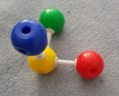
In most cases, specific colors are linked to the coordinate letter, red to X, green to Y, blue to Z (RGB), so I'll follow to this convention. It's helpful to visualize the coordinate system for every joint, and chemistry kit helps, sulfur or boron as the middle element for 90 degree angles (if you like DIY, there are some kits on thingiverse):
¶ Transformation parameters
DH is using 4 parameters:
- rotation by Z axis
- translate by Z axis
- rotation by X axis
- translate by X axis
To give maximum flexibility, robot kinematics allows two additional parameters:
- rotation by Y axis
- translate by Y axis
The order of transformations is important, because matrix multiplications' orders are not commutative. DH transformations are in the order ZX, the extended version ZYX (which is the same order like RPY in aviation).
The transformations are 4x4 matrices as described above and are chained to calculate the complete transformation from base to endpoint. The result is a position and orientation of the endpoint (e. g. hotend nozzle, drill tip).
The traditional DH parameters start with joint 1 and assumes the first axis being vertical (like the 3D printing coordinate system with X to right, Y behind, Z to top). The model includes the base coordinate in A0 and can turn the first axis and displace it, so the robot's origin can have X, Y, Z offsets. Using the M669 B parameter gives unlimited DH parameters.
¶ Finding the parameters
To find the correct coordinate system of an axis, those steps are necessary:
- set the direction of the Z axis, which is the actuator's rotation or prismatic (linear) axis. The direction includes not only the angle, but also the direction (arrow)
- for a rotary axis, decide where the 0 angle is placed. This is the X axis position, corrected by a fixed theta angle. Theta and the actuator angle are added. For a prismatic axis, the 0 position is defined by the coordinate origin, the X axis orientation is not important for defining the 0 position
- the Y axis is given by the right hand rule and perpendicular to the Z and X axes
- measuring and setting the displacements
The DWC plugin RobotViewer helps with the configuration.
¶ Example 1 joint 1
For the following examples, the DH parameter table from this video is used.

The example 1 is from the video, in position where all angles are 0, time 0:29 of video. Axis 1 is rotated left 90 degrees and axis 3 is rotated by 90 degree, so from arm the robot arm are horizontal.
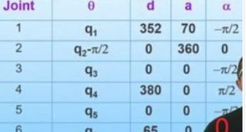
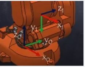
The calculation of the DH parameters for joint 1 is:
- joint 1 is where the coordination system 0 is drawn, this is a bit confusing, but correct (named classic DH naming).
- at the beginning, Z points to top, X to right, Y right hand rule *) to the back
- theta rotation around Z axis is made, which is by vertical, by 0 degrees, so no change
- d is 352 mm direction Z to top, so coordinate originin of coordination system 1 is now 352 higher than coord system 0
- alpha -90 means rotating around X axis clockwise looking at the arrow, which means Z is changed from top to horizontal, pointing to back. X is unchanged, Y is right hand rule (pointing downwards now)
- a 70 is the distance between the Z axes for a perpendicular line between the two Z axis straights and 70 in X direction, so axis 2 is placed 70 to the right of axis 1. It is not visible, but it is the arm 1 length between joint 1 and joint 2.
- it doesn't matter whether rotation theta or displacement d is made first (or alpha or a first) (commutative), but the order of Z (theta, d) first, then X (alpha, a) is important (not commutative).
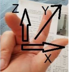
*) it is recommended to do warm-up exercises before trying. Take right hand, thumb to the X direction, middle finger which is 90 degree snapped off to the direction of Z, then index finger which is straight points to the Y direction. (BTW a minute ago I got wrong results with the rule - then I became aware that I used the left hand....)
¶ Example 1 joint 2
Let's analyze DH for joint 2 of the above robot:
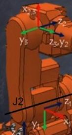
The following steps are processed:
- for joint 2, coordinate system 1 is at the position of joint 2
- the result of the DH transformations (theta, d, alpha and a) is visuable in coordinate system 2, drawed at the position of joint 3
- first theta, rotation around Z axis, by q2-pi/2, which means rotating the variable and additionally by -90 degrees. (pi/2 is 1/4 of the circumfence 2*pi in rad). Looked from rigth to the blue arrow, minus means clockwise, so X axis rotates from right to top and Y from down to right. Theta is always the axis where the variable rotation is around. Z must be correctly set from the joint before. The direction of the axis is important, here arrow is pointing to the back. Adding a fixed -90 degrees to the variable theta rotation angle results in the unusual fact that 0 degree means the arm 2 pointing vertical to the top instead of 0 degree being a horizontal arm 2. DH allows this flexibility, the resulting complete kinematics calculation does not change (hopefully...).
- d is displacement in Z direction by 0. The displacement is in respect to i-1 coordinate system, so no offset between axis 2 and axis 3 (arms 2 and 3 are in one line)
- alpha would be rotation around X axis, but is 0. Z2 is already in the direction of the next axis, so no rotation is needed.
- a is the distance between Zi-1 and Zi axis, perpedicular to both straights. If alpha is 0, 180, 90 or -90 angles, it is the arm length.
¶ Example 1 joint 3
Joint 3 has DH parameters theta=q3, d=0, alpha=-pi/2 (-90 degrees), a=0.
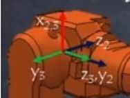
The following calculations are made to convert the coordinate system from O2 to O3 (the coordinate systems are abbreviated to Oi):
- theta is unchanged. Theta is the variable axis rotation, which is axis 3 and horizontal, direction to the back, so positive angles are counterclockwise and mean lowering the arm.
- d=0 means no displacement in Z direction (of old Z2)
- alpha=-90 degree means rotating clockwise by X axis looking from above to the arrow. This results in Z axis to rotate from back to right, and Y2 from right to front Y3.
- a=0 sets the arm length to next joint to 0. The length between joint 3 and joint 4 are added to joint 4 later (as d parameter, because arms direction is axis Z now), because joint 4 doesn't change the angle between both arms. This is not optimal, because later the joint 3 and 4 parameters could be changed later to account for buidings imperfections and the addition of arm lengths is an error then.
In reality, arm 2 and arm 3 are not at the same offset. But the construction of axis 1 to arm 2 in one direction and arm 3 back the same distance makes possible to set d=0 for joints 2 and 3. This is possible, because axis 2 and 3 are parallel to each other. Arm 3 is directly above axis 1 in respect to Z1, Z2 direction. But joint 3 has 70 offset (right of in the image) of axis 1 in respect to Y2, Z3 direction. Those combining of parameter values intend to ease calculations and parallel axes don't have d values, but I recommend so set the values, so the axes coordinates are where the axes are in reality. For two reasons:
- saving calcuation effect is no argument, as there are hundreds of trigonometric calculation and 4 more is really not important
- a later introduced method to calculate back from a measured endpoint to calculation of true axis and arm lenght values is only working, if the DH parameters are placed to axes where they are in reality
DH parameters do not allow to set joint 3 to the location of axis 4, because a translation in the direction of the y axis (Y2) would be needed, and DH parameters allow only rotations and translations around Z and X axes. To solve it, additional M669 B parameters were added to define all 6 parameters to define all possible axis translations and rotations.
¶ Example 1 joint 4
The DH parameters for joint 4 are theta q4, d=380, alpha 90 degrees and a = 0.
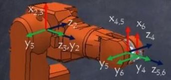
Joint 4 is the nice roll component in the middle of the image.
The calculation of the coordinate system is:
- starting from coordinate system 3, O3, with Z3 to the right, X3 to top, Y3 to the front. Placed at joint 4 (not in the image, the reason being d)
- theta q4 means the variable is to rotate around the Z axis later. This axis is called roll in the RPY (roll-pitch-yaw)
- d=380 displayment includes the length from joint 3 to joint 5, which is possible, because joint 4 is straight.
- alpha 90 means counterclockwise rotation around X axis viewed from above. This rotates Z3 to Z4 direction to behind now, and Y4 with direction to right now.
- a=0 means there is no displacement in X axis direction.
¶ Example 1 joint 5
Joint 5 is also called pitch and has DH parameters theta variable, d=0, alpha=-90 (- pi/2), a=0.
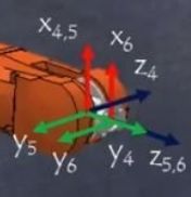
The coordination axes are calculated as follows:
- theta is the rotation around Z axis, where the Oi-1, i.e. Z4, is used, pointing to behind. The rotation is called pitch, coming from airplane roll-pitch-yaw terminology.
- d=0 means the Z axis has no displacement between axis 5 and 6
- alpha=-90 means rotation around X4 axis clockwise, i. e. resulting in Z axis rotating from behind Z4 to right Z5, and Y4 from right to front Y5.
- a=0, because there is no displacment in the X axis direction.
¶ Example 1 joint 6
The DH parameters are theta variable, d=65, alpha=0 and a =0.
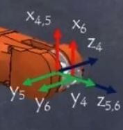
The following changes are made
- theta is 0, so there is no coordinate system change between X, Y from i-1 to i (5 to 6) axes due to Z rotation. X5, Y5 and X6, Y6 stay at their orientations
- d=65 means displacement by 65 in Z direction, which is the displacement of the coordinate systems in the image, being the O6 a bit right from O5. (O stands for origin, the origin of the coordinate system).
- alpha=0 means no rotation around X axis, so no additional change for the direction of Y or Z axis.
- a=0 means there is no displacement between Z5 and Z6 (arm length).
If joint 6 is revolute, then Z is directed to the direction of the end effector. For additional guidelines for DH parameter settings, please see Siciliano et al Robotics Modelling..., chapter 2.8.2, pages 62 f.
¶ Example 2
The same robot in homing position with all theta angles being set to 0 with exception of 1 and 3. The DH parameters of example 1 are used for construction setup, but now additionally with a set of actuator/stepper (theta) angles.
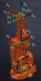

I abbreviate explanation, as example 1 was detailed. The following remarks:
- theta of link1 being 90 and link3 being -90, the whole robot was turned left and link 3 pointing upward, because in the 0 position, the robot is snapped off.
- the image is rotated, the direction of the coordinated systems is changed (only in the image)
- as is shown later in the video (time 8:20), the homing position is in a singularity with two lost ranks (6 joints, 4 ranks). This position must be avoided for normal operation. One effect of being near or at singularity is, that some actuators have very high acceleration/deleceration rates. The inverse kinematics cannot be calculated from inverse Jacobian matrix. Instead, Moore-Penrose must be used to find a way out of the singularity, which means higher calculation time.
¶ Links and additional examples
A good page is
https://automaticaddison.com/homogeneous-transformation-matrices-using-denavit-hartenberg/
with some examples, the last one a 6 axis Fanuc LR Mate 200iD robot.
A nice video for visual explanation of DH parameters is https://www.youtube.com/watch?v=rA9tm0gTln8
A good introduction to kinematics and inverse kinematics is https://www.rosroboticslearning.com, Jacobian method 2 will be used for inverse kinematics.