This page is part of multiple pages about robot configuration and usage. Please choose the robot tag to see an overview.
¶ Introduction
For palletizing, it is advantageous if the endpoint stays horizontal to move the load. For this application, palletizing robots were developed. Some of them are industrial 6 axis robots, but others spare an actuator by a specific parallelogram mechanic. This second type is described in this document. It can also be used for printing or other use cases.
The endpoint's horizontal orientation is ensured by mechanical parallelogram (often two connected parallelograms) based parallel arms. ABB IRB 460, Fanuc M-410, EEZYbotARM (thingiverse 1454048), MK2 plus (thingiverse 2520572) and R290 3 axis are examples. A similar construction, but with the stepper 3 directly connected with the arm, are handled with this construction as well, like the Kuka KR 700 and Borunte BRTIRPZ. The important property is axis 4 without actuator, which is parallel to the base plate by mechanical means.
Robots like ABB IRB 8700 and Stäubli TX340 SH use a parallelogram as well and seem to be type 4 axis palletized, but they have only a parallelogram to place the motor of arm 3 to the axis 1 plate. They can be modeled with the normal industrial 6 axis robot configuration.
If an endpoint is assembled vertical to the horizontal plate at the end, the Z axis (hotend, drill) stays vertical. However, the Z axis rotation angle changes when position changes with respect to the coordinate system. This may be a disadvantage. The option is to install a 4th actuator at the plate.
Another variant is to install the workpiece on the robot and have hotend or spindle stationary. An example configuration will be provided => tbd
¶ Role of the 4th actuator
An optional 4th actuator (if the passive 4th axis is counted, it is axis 5), is meant to rotate a gripper or other endpoint tool. I. e., it is not meant to be used for positioning. The first three actuators are sufficient for positioning: axis 1 for the angle of a circle, axis 2 and 3 to define the distance from axis 1 and Z height:
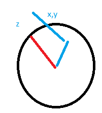
The optional 4th actuator (axis 5) position change (by rotating, XY is changing) is not taken into account to reach the G-Code cartesian coordinates. Instead, the middle axis coordinate of the 4th actuator is taken as endpoint, with additional G10 offsets of the tool (hotend, drill). The 4th actuator can be controlled by it's drive letter, but it (in this release) doesn't change XYZ cartesian coordinates in the firmware. If the tool has 0,0 XY offset from the 4th actuator, rotating it will not change the XY position, but only the orientation of the endpoint (rotation by Z axis).
¶ Construction
As example a 4 axis palletize robot which can be found as R290 3 axis robot (3 axes with actuators, 4 th passive axis):
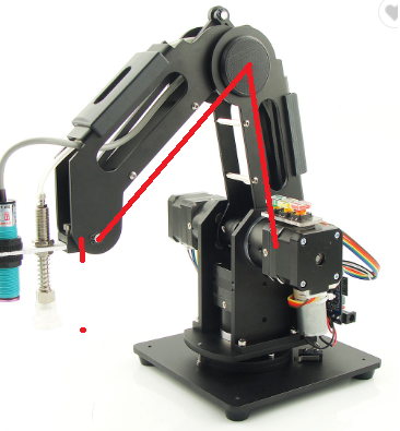
The first stepper drives axis 1 and decides about the direction angle. Stepper 2 drives the first big arm. Stepper 3 changes the second big arm by a parallelogram construction, so arm 3 is rotated remotely. Stepper 4, if it exists, allows rotation of the endpoint around a 5th Z axis. A 2-stage parallelogram based arm construction assures that the endpoint platform is always parallel to the base.
Axis 2 and 3 are constructed as follows:
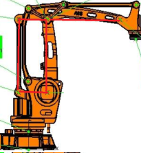
Steppers 2 and 3 axes have the same axial position and form a parallogram with the arm2-arm3 joint and the thin supporting arm on the left. A stepper 2 / arm 2 angle changed doesn't change the arm3 angle and vice versa. The focus of the motors is low, below the arm construction, which is advantagous.
The endpoint plate stays horizontal by the following construction :
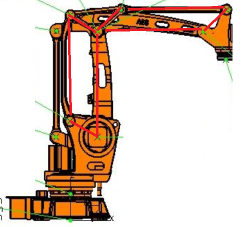
Changing arm 2 will change the lower parallelgram, changing arm 3 will change the right parallelogram. Both parallelgrams are connected by the triangle, so the angle of base is transmitted to the endpoint plate, which remains parallel to the base.
¶ Workspace, (Singularity)
The workspace looks like a donut:
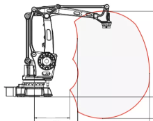
I am currently not aware of a singularity inside the workspace.
¶ Homing, arm lenghts
Axis 1 and if it exists axis 5 (4) is configured as usual: homing and setting the angle to the correct value in respect to the choosen coordinate system.
When being homed, axis 2 and axis 3 references are the two red long lines in the R290 image: the lines between the joints, not the arms themselves.
The short red line is the distance between the last joint and the assembly plate in Z direction. The same offsets can be set for X and Y direction. The offsets can be set at the G10 tool offsets alternatively. When using a tool changer, it will be easier to set them separately.
The arm lengths are the lengths of the red lines also, i. e. the distance of the joints, not the physical arm lengths. The arms could have different forms (e. g. curved), this doesn't change the configured values. Curved arms could have the advantage to give bigger min&max angles.
¶ Configuration
The setup can be made with A parameters, describing Denavit-Hartenberg (DH) parameters, or with B parameters.
| M669 K13 B"axisTypes=RRRp" | 3 actuators with 4 axes |
| M669 K13 B"axisTypes=RRRpR" | 4 actuators with 5 axes |
| M669 K13 B"axisTypes=PRRRp" | 3 actuators version on linear rail |
(p must be lowercase. Uppercase P would mean prismatic joint)
If robots plate is used to place the object and the endpoint (hotend, drill) is installed above stationary, the robot must be set into reverse mode to change axis directions.
Default is axis 1 being vertical, axes 2 to 4 (4 is without actuator) being horizontal and parallel, axis 5 vertical again. Positive angles are CCW from above for axes 1 and 5, 0 degrees being in the X direction. For axes 2 to 4, positive angles are CCW seen from front, 0 degrees being the horizontal position (this can all be overritten by DH parameters).
The 4th axis is calculated from axes 2 and 3: angle 2 + angle 3 + angle 4 = 0.
¶ An example DH definition looks like this:
M669 K13 B"axisTypes=RRRp"
; DH parameters:
D"0:0.0:0.0:0.0:0.0"
D"1:200.0:0.0:70.0:90.0"
D"2:0.0:0.0:100.0:0.0"
D"3:0.0:0.0:100.0:0.0"
D"4:0.0:0.0:0.0:90.0"
D"5:100.0:0.0:0.0:0.0"
; Angles:
A1:-180.0:180.0:0.0
A2:0.0:120.0:0.0
A3:-100.0:0.0:0.0
A"RRRp" means 4 rotational axes, where the 4th one is an axis with automatic angle by parallelogram.
D0 is the base, unchanged here. Coordinate system is X right, Y back, Z top.
D1 is 200 mm height, Z direction, of start of axis2 and 70 mm in X direction. Axis1 can rotate between -180 and +180 degrees, the homing angle (the angle which is set when the endstop is triggered) is 0 degrees. Xrot is 90 degree, which changes the coordinate system for axis 2 to Z front, X right, Y top.
D2 defines the arm which is attached to axis2, min angle 0, home angle 0 and max angle 120 degrees. Coordinate system is unchanged, i. e. axis 3 was same direction like axis 2.
D3 defines next main arm as 100 mm, min angle -100, home 0, max 0. Coordinate system is changend, because axis4 has same orientation like axis2 and 3.
D4 defines to rotate X axis by 90 to prepare correct orientation of the tool. The angle by Z axis is automatically set by the parallelogram, but if an angle is set here, it will be added to this value.
D5 is the tool setting. G10 offsets will be added to the values.
A1 to A3 define min, max and optionally home angles. A4 can be defined for min and max, if there are technical angle restrictions to the angle. Angle violations will be reported with a G1 error message and the planned move will fail partly or completely (depending on whether it is a 3D print or CNC/Laser mode. Both will probably ruin the workpiece).
¶ Mesh compensation
When no 5th axis is installed, the endpoint rotates when axis 1 rotates, so mesh compensation with a probe with XY offset <> 0 is not possible by default. A solution is to define the probe as if it is a tool and the probe being at tool's position: defining G10 to point to the probe, and setting probe properties to XY 0,0 offset. Then measuring and storing the results with the correct coordinates. Then setting back the G10 properties to the true tool offsets, then print with mesh compensation activated.
¶ More information
A very good explanation of the IRB 460 robot is the article "17. Cristoiu and Nicolescu, New Approach For Forward Kinematics Modeling of Industrial Robots with Closed Kinematic Chain", which can be found as pdf. Firmware uses a simpler method for calculation than described in the document, assuming that the endpoint platform is parallel to the base.