¶ Introduction
Various Duet 3 toolboards have a builtin accelerometer. However for systems not using a toolboard, this small stand alone accelerometer can be used. It connects to the SPI Daughterboard header (also labelled Temp DB on earlier Duets) with the supplied 1m ribbon cable. Accelerometer readings captured can be used to tune input shaping parameters to avoid ringing artefacts.
¶ Features
| Duet3D Accelerometer v0.2 | Duet3D Accelerometer v1.0 | |
|---|---|---|
| Accelerometer | LIS3DH | LIS2DW12 |
| Supply voltage | 3.3V - Do not connect to 5V it will be damaged | |
| Interface | SPI Slave - Duet Mainboard is SPI master | |
| LED | There is a green LED on the board to indicate power is applied | |
| Maximum ambient temperature | 85°C | |
| Additional details | LIS3DH datasheet | LIS2DW12 datasheet |
¶ Firmware notes
- Duet3D Accelerometer v0.2 is compatible RepRapFirmware v3.4.6 or v3.5beta4 and later
- Duet3D Accelerometer v1.0 is compatible RepRapFirmware v3.5.0-rc.2 and later
¶ Physical properties and connections
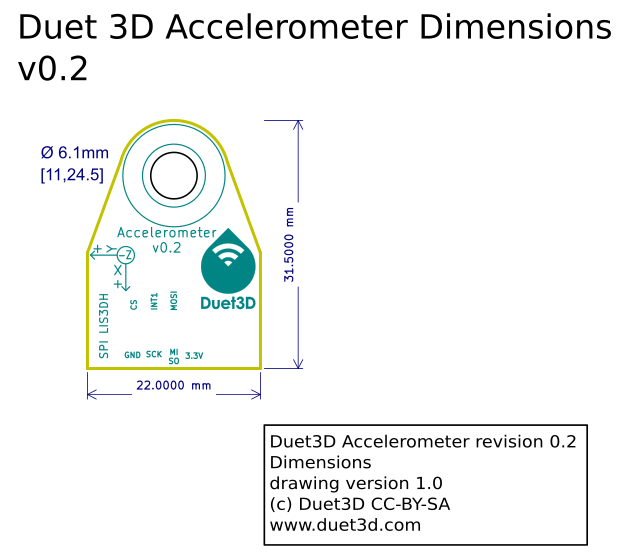
¶ Dimensions
¶ Mounting
The hole in the PCB is 6.1mm so it can be mounted using a standard 3d printing nozzle as well as systems like the Revo nozzles:
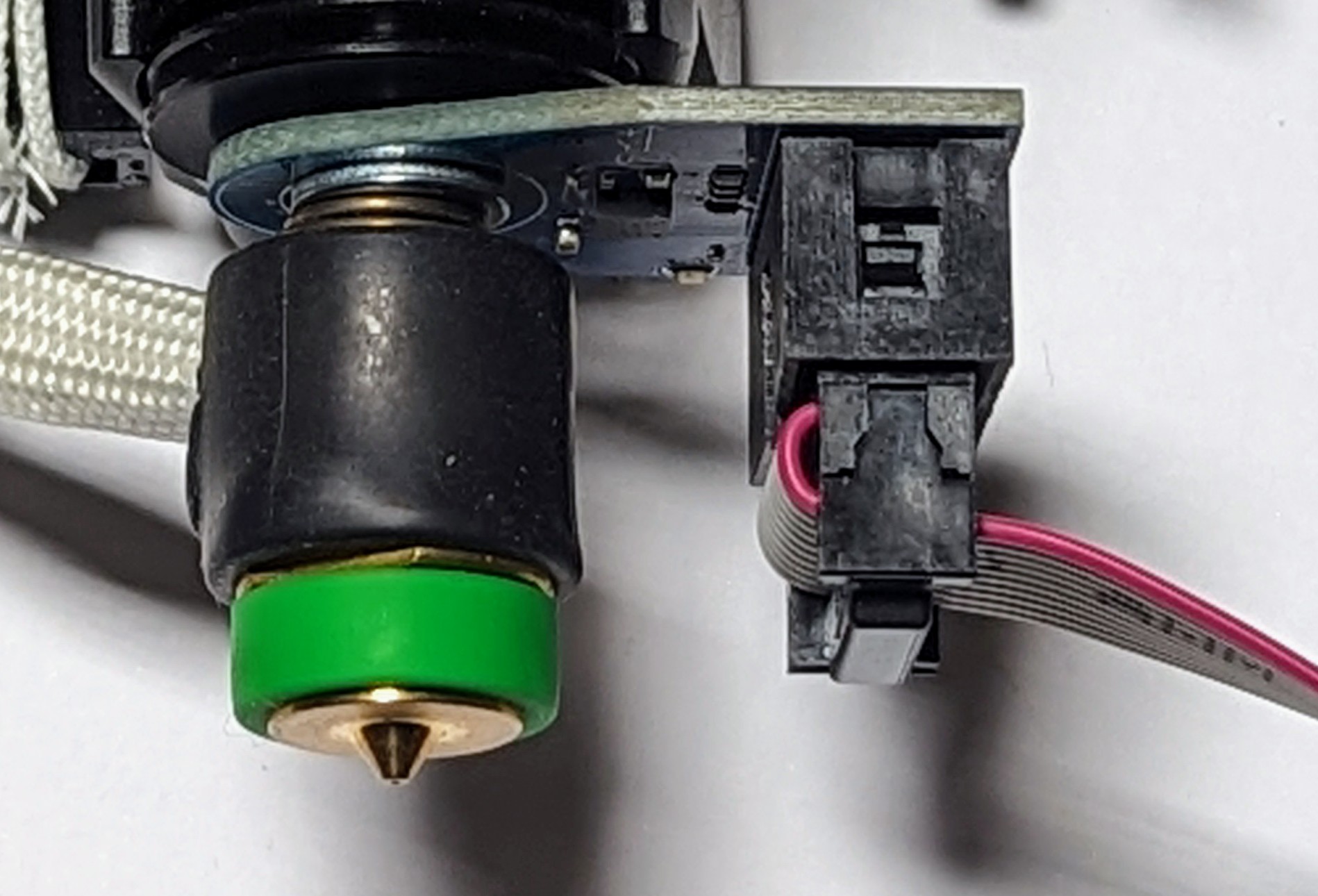
The accelerometer needs to be firmly mounted for data collection so it the nozzle is <6mm (such as the revo) use a m4 washer between the flanged top of the revo heatbreak and the accelerometer PCB. This is not necessary for V6 and similar nozzles.
In the case of the revo the spring holding the heater core against the end of the nozzle is not sufficent to hold the accelerometer PCB firmly in position by itself, hence the requirement to mount it using an M4 wahser and the flange of the nozzle.
Note the orientation of the accelerometer board is important the correct data collection and analysis, see the orientation section below.
WARNING: Do not heat the hotend with the accelerometer mounted using the nozzle.
Manually set the active and standby temperature to 0°C before using the IS plugin.
¶ 3D model
A STEP 3D model is available on github.
¶ Wiring Diagram
¶ Wiring notes
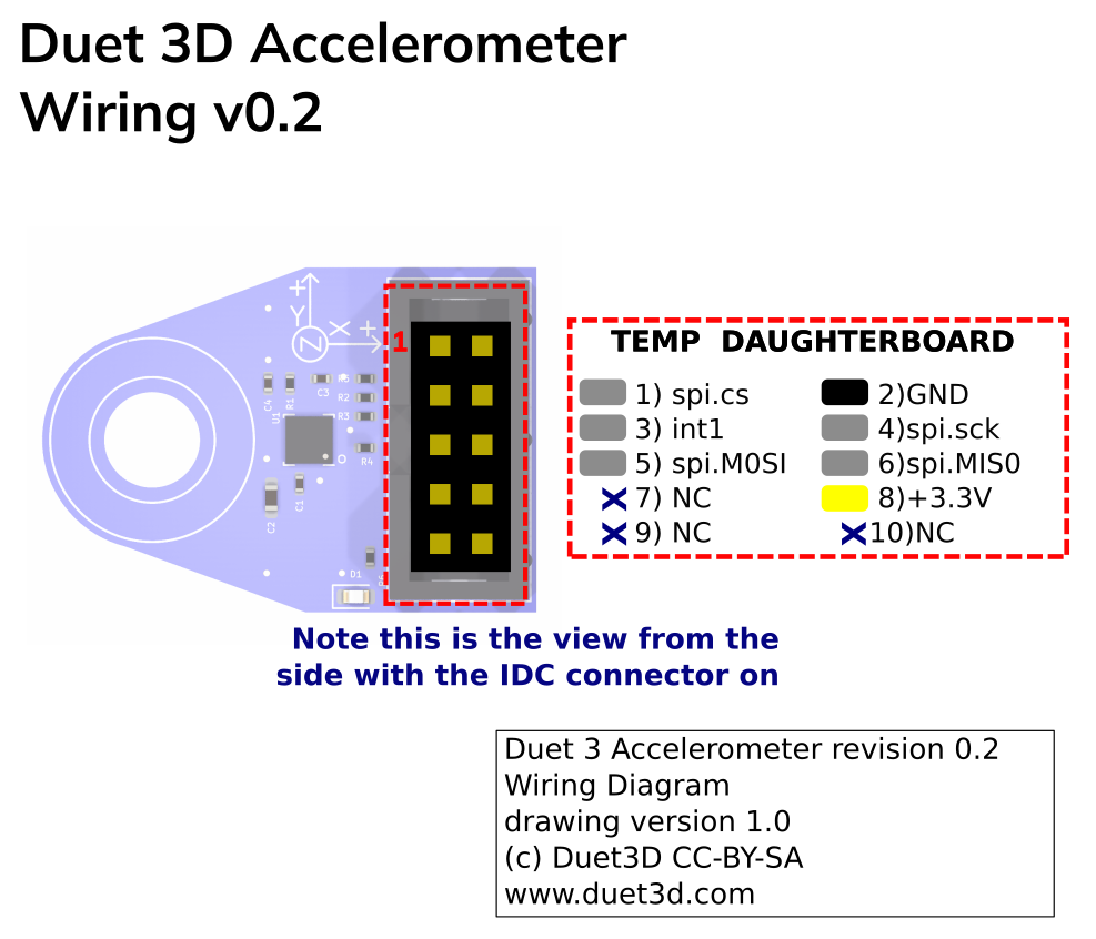
The accelerometer comes with a 1m long 10 way IDC cable that plugs directly into the SPI DB header on Duet mainboards. Ensure the connector orentation is correct so pin1 on the IDC goes to pin 1 on the mainboard:
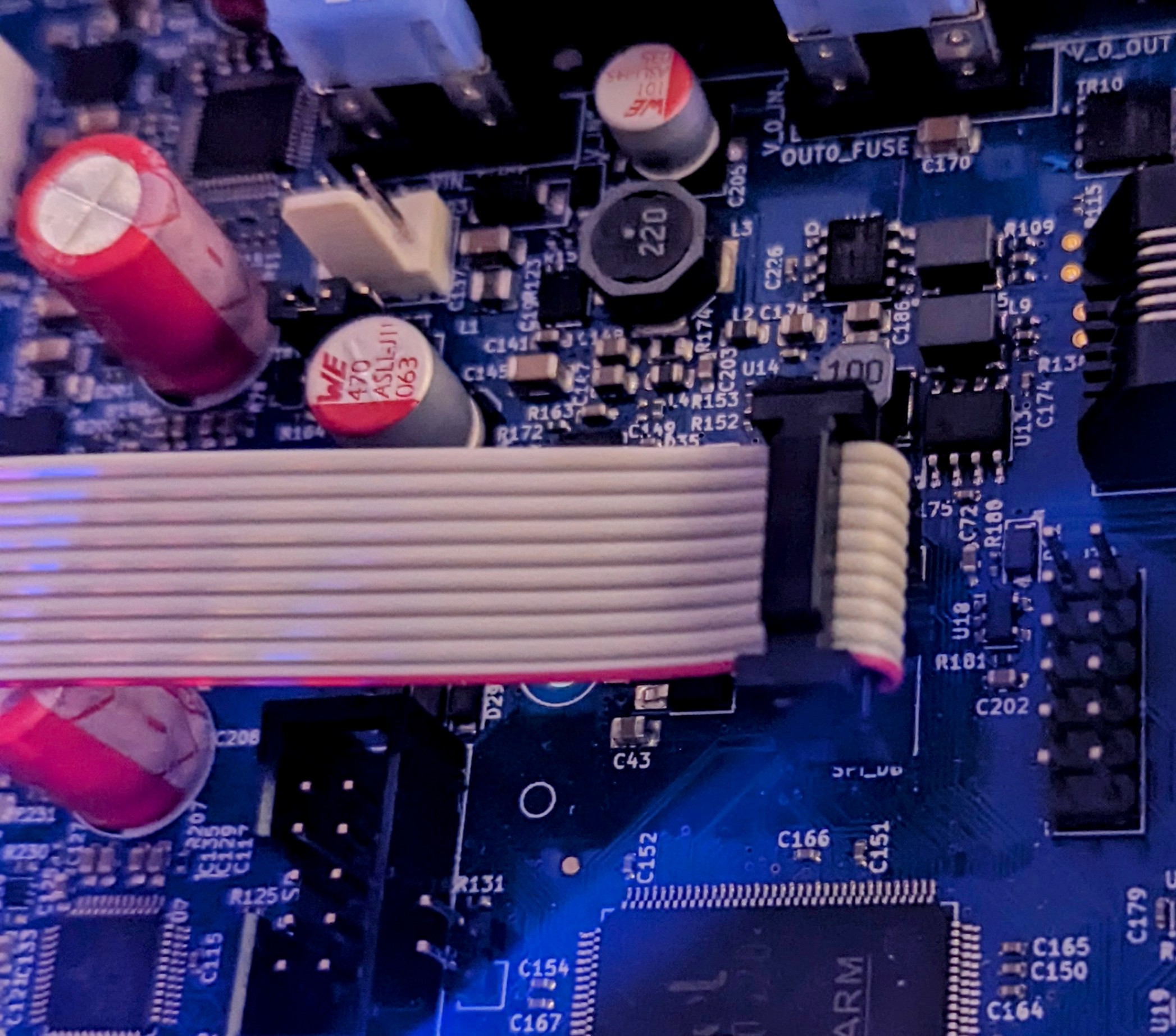
Duet3D accelerometer connected to the Duet 3 6HC mainboard
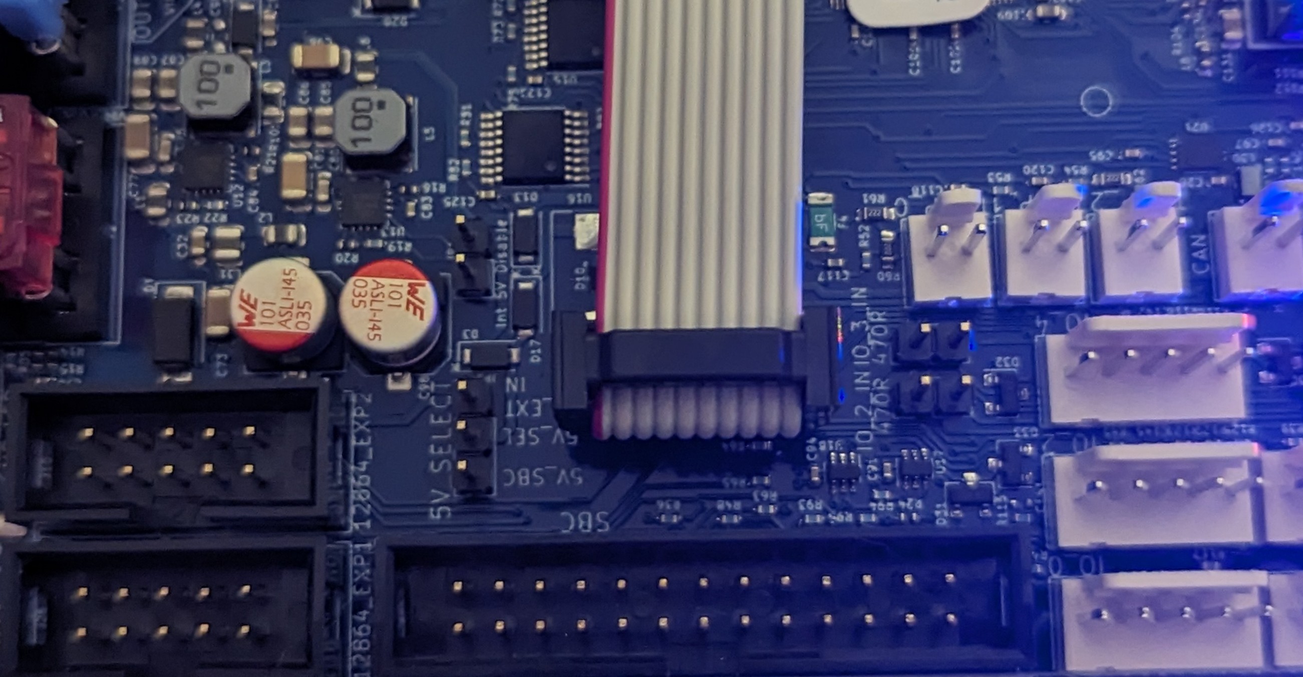
Duet3D accelerometer connected to the Duet 3 Mini5+ mainboard
¶ Orientation
The I (orientation) parameter tells the firmware which of the 24 possible orientations the accelerometer chip is in relative to the printer axes. It is expressed as a 2-digit number. The first digit specifies which machine direction the Z axis of the accelerometer chip (usually the top face of the chip) faces, as follows: 0 = +X, 1 = +Y, 2 = +Z, 4 = -X, 5 = -Y, 6 = -Z. The second digit expresses which direction the X axis of the accelerometer chip faces, using the same code. If the accelerometer chip axes line up with the machine axis, the orientation is 20. This is the default orientation if no orientation has been specified.
In all the images below the image of the accelerometer is shown as if stood in front of a "normal" machine where X+ is to the right and Y+ is towards the back
| Accelerometer axis to machine axis | ||||||
|---|---|---|---|---|---|---|
| +X to +X | +X to +Y | +X to +Z | +X to -X | +X to -Y | +X to -Z | |
| +Z to +X | NA |  M955 P[##] I01 |
 M955 P[##] I02 |
NA |  M955 P[##] I05 |
 M955 P[##] I06 |
| +Z to +Y |  M955 P[##] I10 |
NA |  M955 P[##] I12 |
 M955 P[##] I14 |
NA |  M955 P[##] I16 |
| +Z to +Z |  M955 P[##] I20 |
 M955 P[##] I21 |
NA |  M955 P[##] I24 |
 M955 P[##] I25 |
NA |
| +Z to -X | NA |  M955 P[##] I41 |
 M955 P[##] I42 |
NA |  M955 P[##] I45 |
 M955 P[##] I46 |
| +Z to -Y |  M955 P[##] I50 |
NA |  M955 P[##] I52 |
 M955 P[##] I54 |
NA |  M955 P[##] I56 |
| +Z to -Z |  M955 P[##] I60 |
 M955 P[##] I61 |
NA |  M955 P[##] I64 |
 M955 P[##] I65 |
NA |
¶ Configuration and use
See the connecting an accelerometer page for details on how to configure and use the accelerometer
See the input shaping page for details on how to use input shaping.
¶ Revision History
- LIS3DH accelerometer replaced with LIS2DW12
- Initial version
