¶ Introduction
The Duet3D DuetScreen is a family of colour touch screen controllers for Duet 2 and Duet 3 based machines. It is also compatible with other Controllers running RepRapFirmware.
The current hardware implementation is the DuetScreen 7, other screen sizes are planned in the future.
The DuetScreen application is built on LVGL and provides a modern machine control UI, initially focused on 3d printers. Its modular design allows for future versions for other machine types.
¶ Features
¶ Hardware Specification
¶ DuetScreen 7
| HARDWARE SPECIFICATION | |
|---|---|
| Processor | Allwinner T113-S3 |
| Processor features | Dual-core ARM Cortex-A7, 1.2GHz, 128Mb RAM |
| Screen Resolution | 1024*600 |
| Touch Screen | Capacitive |
| Networking | Onboard WiFi module, option for internal or external antenna |
| USB | 1x USB-A and 1x USB-C 2.0 ports |
| Serial | 3x UART, 1x USART 1 |
| Other Comms | 2x I2C 1 |
| Buzzer | On Board Piezo Buzzer |
| Speaker | Header to connect an 8 Ohm mono speaker |
Note: 1 Not populated in version 1.0 hardware or explicitly supported in the DuetScreen software.
¶ Operating limits
| Input voltage | 5V to 5.3V |
| Input current | 250-500mA, depending on enabled feature and brightness, excluding external devices on USB 2 |
| 5V current on USB | 500mA total 2 |
| Maximum ambient temperature | 70°C |
Note: 2 See the powering the screen section below.
¶ Software and Firmware notes
¶ DuetScreen
The DuetScreen runs a lightweight version of linux based on Buildroot, this is designed for embedded systems and allows for fast startup. The UI is built on LVGL.
More information for developers is available on our github repositories (note currently private, will be made public in due course):
DuetScreen
buildroot-duetscreen
¶ Physical properties
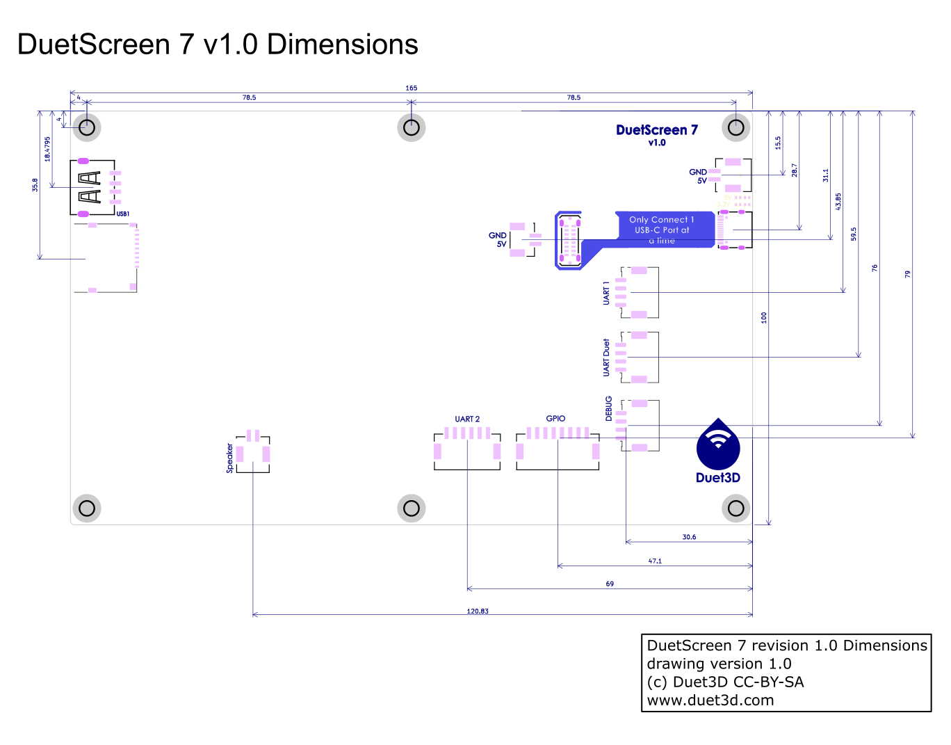
¶ Dimensions
¶ Mounting
The DuetScreen 7 has 6 mounting posts, these are M3 tapped, 8mm high posts soldered into the board. In many cases only the outer 4 will be required.
Do not over torque screws into these mounting posts. They are rated to 0.5 Nm, however to mount the screen there is no need to go above 0.2 Nm
¶ 3D model
A zip of the STEP file for the screen is here: duet_screen_7_1.0_step.zip
¶ Enclosure
¶ Duet3D reference enclosure
This enclosure is designed by chrishamm, The Zip file contains both the STEP file and a FreeCAD 1.0 project.
case_duetscreen_v1.0.zip
Tony has made some minor tweaks to Christians design which are available here: case_duetscreen_v1.0_tony_mod.zip
¶ Connecting a DuetScreen
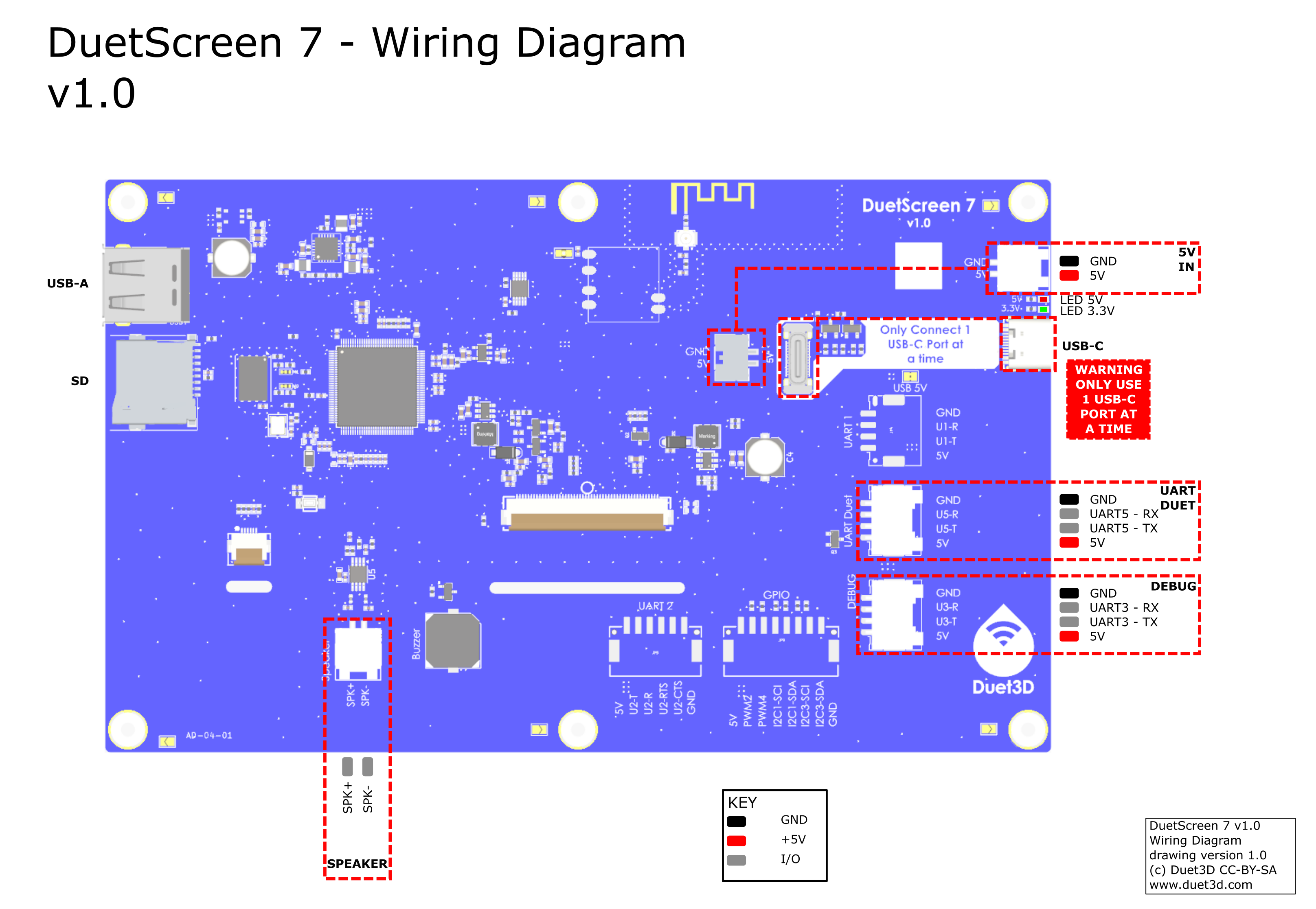
¶ Wiring Diagram
 !
!
¶ Powering the DuetScreen
All the power inputs are NOT isolated. This means that if you connect the DuetScreen to a mainboard via USB or UART, the screen and the mainboard should share a common ground. The easiest way to do this is to power the screen from the mainboard. If you do not do this, you may damage the DuetScreen or the mainboard.
The DuetScreen can be powered in the following ways:
- 5V_IN: This is the recommended method when connecting over USB or WIFI.
- USB-C: This is fine when using WIFI.
- UART5: This is a legacy method for compatibility with PanelDue wiring. It is not recommended for new installations.
¶ USB Ports
The DuetScreen has two USB ports:
USB-A: This port is a host port.
- Its primary purpose is for USB Flash drives to be connected, currently for software upgrades and potentially for print files in the future.
- It is possible to use it to connect to a Duet3D mainboard, or external wifi module as well.
USB-C: This port can be a host or device port.
- It can be used to connect to a Duet3D mainboard in host mode
- It is possible to use it to add and external wifi modules or USB flash drives in host mode (although the USB A port may be easier)
- It can be used to connect to a PC in device mode for software debugging.
- It can be used to power the DuetScreen in either mode (assuming the attached device/host is able to supply power).
A Duet3D mainboard CANNOT provide power to the DuetScreen via the USB-C. Always power the DuetScreen via the 5V_IN port when using USB
USB hubs are supported if they are NOT smart. A smart hub is one that requires a driver to work. This includes most USB-C hubs. If you are using a USB-C hub, make sure it is a dumb hub. A dumb hub is one that does not require a driver to work. This includes most USB-A hubs. If in doubt, use a USB-A hub.
¶ Connecting to a Duet mainboard
Multiple methods are available to connect the DuetScreen to a mainboard. The recommended method is to use a USB cable. This allows for a consistent connection, not reliant on a wifi network and is the easiest to set up.
The Connection choice is made on the Settings > Connection screen:
- Connect the DuetScreen to the mainboard using a USB cable.
- Either the USB-A and USB-C ports on the DuetScreen can be used.
- If using the USB-C port, make sure USB-C Mode is set to
USB-C Host.
- On the Settings > Connection screen, select the USB connection method.
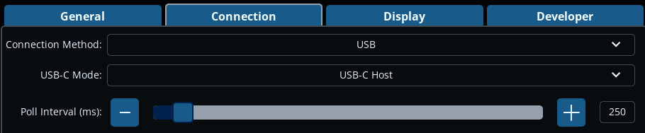
When the DuetScreen detects a USB connection to a Duet3D mainboard, it will automatically send
M575 P0 S4to configure the mainboard for USB communication.
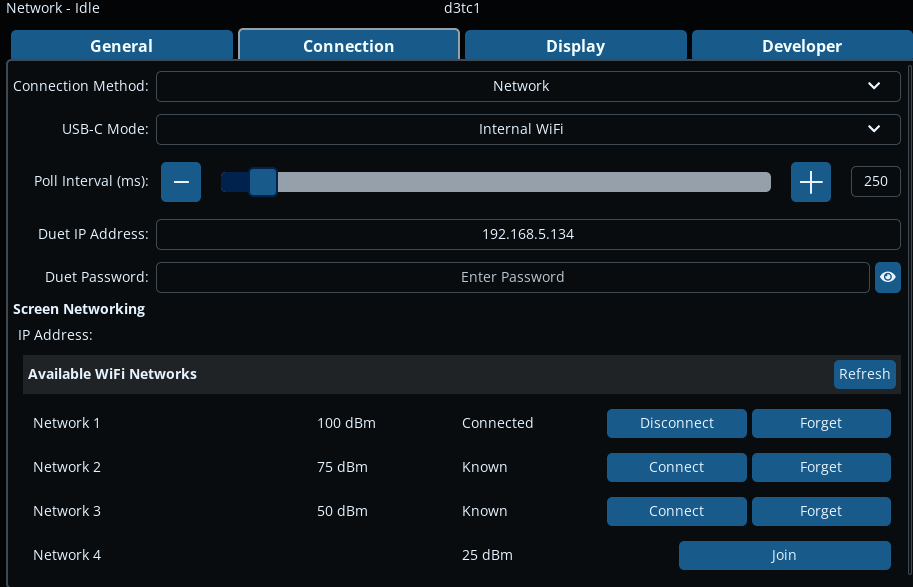
- The DuetScreen has a built-in WiFi module. To use this, on the Settings > Connection screen:
- Set the 'Connection Method' to
Network - Set the 'USB-C Mode' to
Internal WiFi - The DuetScreen should scan for available SSIDs, and list them at the bottom of the screen.
- Set the 'Connection Method' to
- The DuetScreen also supports external WiFi modules with the
RTL8188FUchipset.- If using an external WiFi module, set the Connection Method to Network and connect it to the USB-A port on the DuetScreen, or use the USB-C port and set it to
USB-C Host. - There are multiple variants of the
RTL8188chipset. Currently the DuetScreen only supportsRTL8188FU. Other variants are unlikely to work.
- If using an external WiFi module, set the Connection Method to Network and connect it to the USB-A port on the DuetScreen, or use the USB-C port and set it to
NOTE You may need to reboot the DuetScreen after enabling the WiFi module.
¶ Connect the DuetScreen to a WiFi network
There are a couple of methods to connect the DuetScreen to a WiFi network.
-
You can connect to a network using the Settings > Connections page in the GUI. This method is useful if you are setting up a single DuetScreen and you do not know the WiFi credentials in advance.
- Find your WiFi SSID from the list under 'Available WiFi Networks'. If none are shown press
Refresh. You may need to restart the DuetScreen if you have recently enabled the WiFi module. - Press the
Joinbutton, and enter the SSID password - The button should change to two buttons
DisconnectandForget - The screen's IP address with be set automatically by DHCP (see below for setting a manual IP address)
- You can change SSID by pressing
Disconnectand thenConnectto another SSID - If you press
Forget, the SSID will be removed from the list of remembered SSIDs
- Find your WiFi SSID from the list under 'Available WiFi Networks'. If none are shown press
-
You can copy a file called
wpa_supplicant.confto the root of the microSD card. This file should be placed on the microSD card after it has been flashed. This method is the easiest if you are setting up multiple DuetScreens, or you know the WiFi credentials in advance. This file should contain the WiFi credentials in the following format:ctrl_interface=/var/run/wpa_supplicant update_config=1 ap_scan=1 network={ ssid="your-SSID" psk="your-PASSWORD" key_mgmt=WPA-PSK }
¶ Connect the DuetScreen to a Duet Mainboard
- In Settings > Connections, make sure 'Connection Method' is set to
Internal WiFiconnection method. - Ensure the DuetScreen is connected to the same WiFi network as the mainboard.
- Enter the IP address and password (if applicable) of the Duet mainboard in 'Duet IP Address' and 'Duet Password' fields.
¶ Setting the IP address manually
You can set the screen's IP address manually by creating a dhcpcd.conf file in the first FAT (boot) partition. For example:
interface wlan0

static ip_address=192.168.1.2/24
static routers=192.168.1.254
static domain_name_servers=192.168.1.254
The DuetScreen does not have an Ethernet port, but does support most USB-A/USB-C to Ethernet dongles using generic USB net class device drivers, as well as those using RTL8150/8152/8153 and AX88179A chipsets (as of v1.0.0 firmware).
- To use a USB to Ethernet dongle:
- Plug in the USB to Ethernet adapter into the USB-A or USB-C port, depending on the adapter.
- Power can be supplied by the USB-C to Ethernet adapter, if it supports it.
- Connect a network-connected Ethernet cable to the adapter.
- On the Settings > Connection screen:
- Set the 'Connection Method' to
Network - Set the 'USB-C Mode' to
USB-C Host. (USB-C Deviceis only used to connect to a PC for software debugging.) - The DuetScreen should connect to your network and set the IP address automatically via DHCP (see below for setting a manual IP address).
- Set the 'Connection Method' to
¶ Connect the DuetScreen to a Duet Mainboard
- Ensure the DuetScreen is connected to the same network as the mainboard.
- Enter the IP address and password (if applicable) of the Duet mainboard in 'Duet IP Address' and 'Duet Password' fields.
¶ Setting the IP address manually
You can set the screen's IP address manually by creating a dhcpcd.conf file in the first FAT (boot) partition. For example:
interface eth0

static ip_address=192.168.1.2/24
static routers=192.168.1.254
static domain_name_servers=192.168.1.254
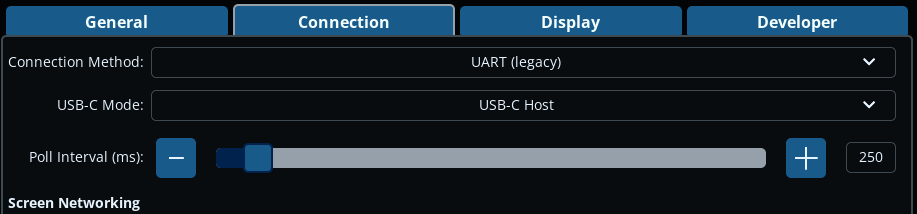
This method is for legacy support only to provide an easy upgrade path for PanelDue users. It is not recommended for new installations.
- Connect the DuetScreen to the mainboard using a UART cable (see below).
- In Settings > Connections, set 'Connection Method' to
UART (legacy). - The 'USB-C Mode' selection is irrelevant in this case.
- Set the baud rate on the Duet mainboard to
115200. UseM575 P1 S4 B115200in config.g. This is similar to connecting a PanelDue, other than the default baud rate is 115200
¶ Wiring
For a Duet3 IO0 port for UART is as follows:
| Duet3 Mainboard - IO0 Connector | DuetScreen - UART Duet connector |
|---|---|
| 5V | 5V |
| io0.out | U5-R |
| GND | GND |
| io0.in | U5-T |
¶ Using a DuetScreen
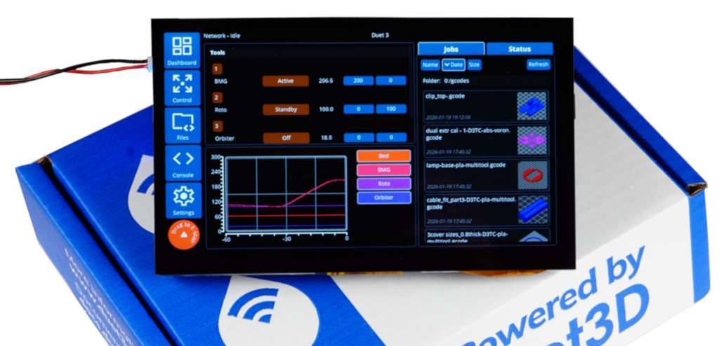
 The Dashboard is the initial screen shown on the DuetScreen after startup.
All other screens and functions are accessed using the menu buttons on the left of the screen. Some screens have tabs to switch between various controls. Buttons that you can interact with are generally highlighted. In the default theme:
- Orange buttons indicate a button is used to change the physical state of a machine, e.g. turn on a heater or move an axis
- Blue buttons indicate a button that changes a setting
If there is too much information to fit in a display area, for example in the list of tools or the list of jobs, a scroll bar will show on the side of the display area. Drag the list up and down to see the full list.
There is an Emergency Stop button in the bottom left corner, and is shown on every screen. To use this, press and drag it a short distance. If you press it by mistake, it will not cause an emergency stop, but you will get a message.
On pages with tabs, the DuetScreen will remember the last tab you visited if you navigate away. For example, if you are viewing the Control > Bed Levelling tab, then go to the Console, when you go back to Control, the Bed Levelling tab will be shown.
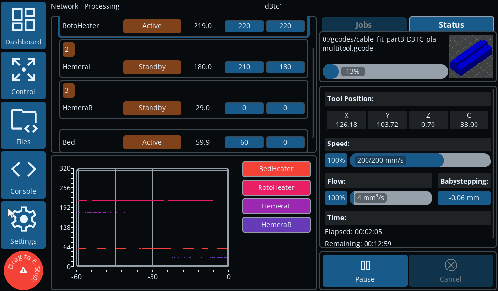
The Dashboard screen gives you a quick overview of the state of your machine.
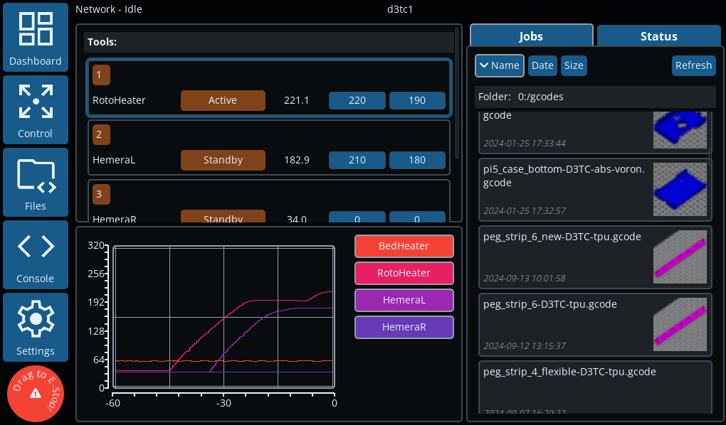 Tools, heaters and temperatures are displayed on the left. The currently-active tool, if any, will be highlighted. Tools can be set to active or standby, and heaters can be set to active, standby or off. Active and standby temperatures can be set. Tools, beds and chamber heaters are all displayed; drag up and down to see the full list.
Heater temperatures are shown on the graph. Heaters can be individually turned off and on by clicking their name next to the graph.
On the right side of the Dashboard screen, there are two tabs.
The Jobs tab shows the list of jobs in the /gcodes folder on the SD card, including sub-folders. The list can be ordered by Name, Date or Size.
Note: job thumbnails will only show once you have clicked on the job to show the detail view (see below). Then the thumbnail will show in the Jobs list.
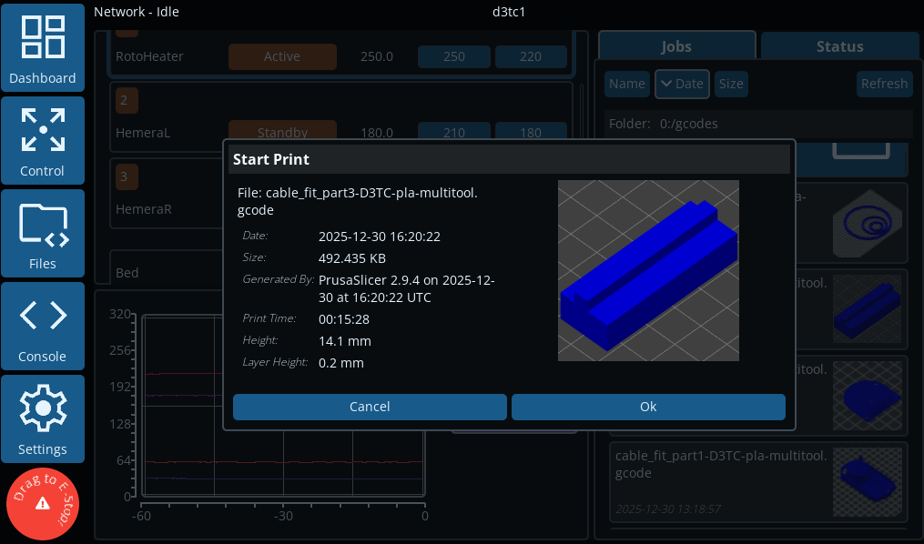 Clicking on a job opens a window with more information on the job and the thumbnail (if available), with options to print or return to the file list.
The Status tab shows the progress of the current job, if one is running. It reports the current tool position at all times. Speed factor, extrusion factor and babystepping controls can be quickly accessed here.
Note: changing values in these dialogue boxes takes effect immediately, not when the dialogue box is closed.
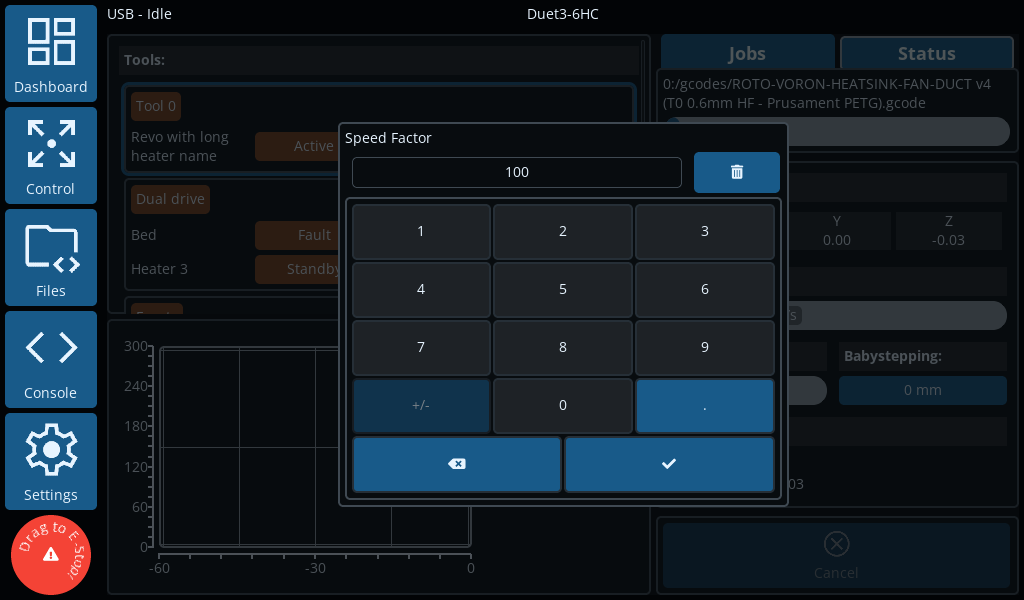 Tapping on the Speed percentage brings up the Speed Factor dialogue box. Adjust the speed factor as necessary.
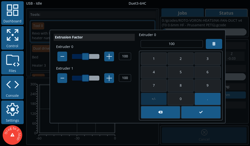 Tapping on the Flow percentage brings up the Extrusion Factor dialogue box. Adjust the Extrusion factor as necessary.
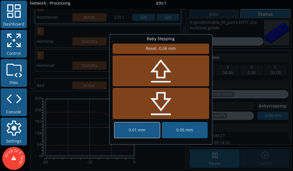 Tapping on the Babystepping setting brings up the Babystepping dialogue box. Adjust babystepping as necessary.
The Control screens give you more fine-grained, manual control over your machine.
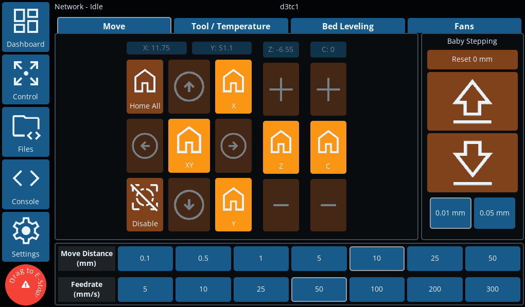 The initial Move tab gives you control over the axes, typically showing the X, Y and Z axes. Additional axes will show next to the Z axis.
There are buttons for homing all axes, individual axes, and disabling motors (M18). These all have confirmation dialogues, to avoid unexpected movement if you press them by mistake.
If axes are unhomed, the homing buttons will be brighter, and the move buttons can not be used.
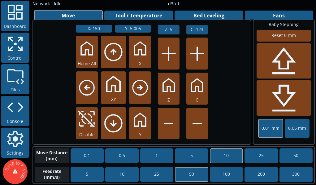 Once homed, axes can be moved using the arrow buttons, or +/- buttons. Distance and Feedrate are set at the bottom of the screen.
Babystepping can be adjusted using the controls on the right side.
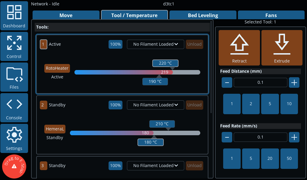 The Tool / Temperature tab gives granular control over tool states.
The currently-active tool, if any, will be highlighted. Tools can be set to active or standby, and heaters can be set to active, standby or off. Active and standby temperatures, and extrusion factor can be set. Filaments can be set, loaded and unloaded.
On the right is the extrusion control for the current tool. Set the distance and feedrate, then use the Retract and Extrude buttons to move the filament.
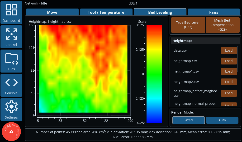 The Bed Levelling tab presents controls for True Bed Levelling (G32) and Mesh Bed Compensation (G29). Previously saved bed meshes can also be viewed and loaded.
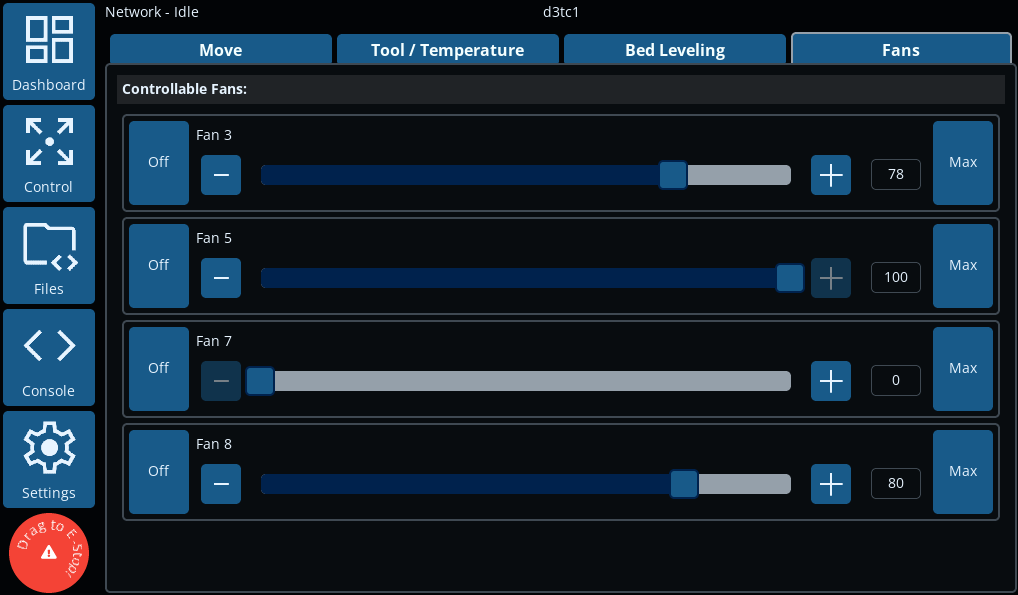 The Fans tab shows currently configured fans, and allows manual control over them. Fan percentage can be set by clicking the "Off" or "Max" buttons, using the +/- buttons to increase/decrease the percentage, or by clicking on the fan percentage and using the fan dialogue to enter the amount.
The Files screen has two tabs, allowing access to files that have been uploaded to the SD card.
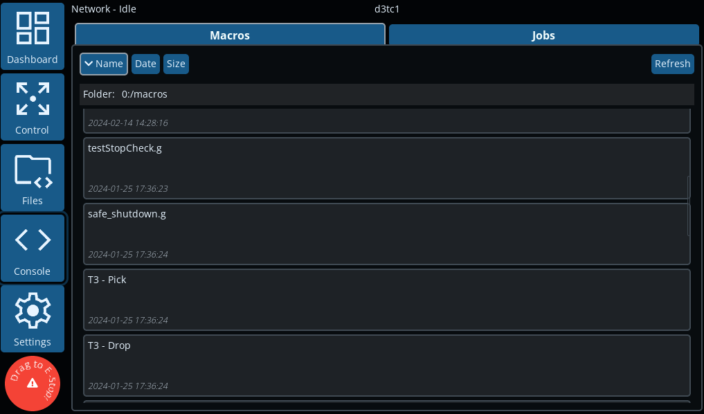 The Macros tab shows the list of macros in the /macros folder on the SD card, including sub-folders. The list can be ordered by Name, Date or Size. Selecting a macro will give you the option of running the macro, or cancelling.
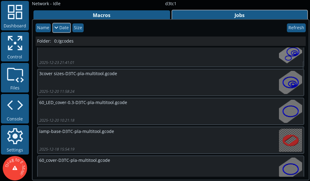 The Jobs tab shows the list of jobs in the /gcodes folder on the SD card, including sub-folders, with any . The list can be ordered by Name, Date or Size.
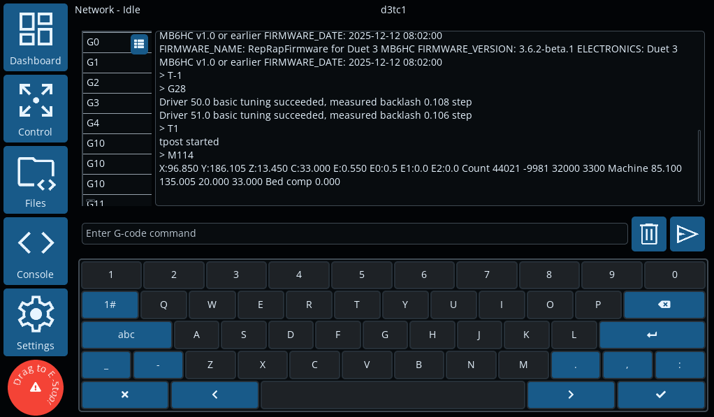 The Console screen provides a serial terminal for sending Gcode commands directly to the Duet. There is also a Gcode command glossary, with brief descriptions of all Gcodes.
The Settings screens allow you to manage and fine tune the DuetScreen for your machine. There are four tabs.
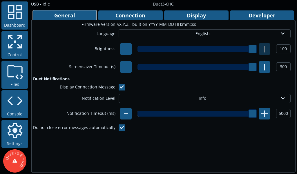 The General tab has settings for initial DuetScreen setup, and message notification handling.
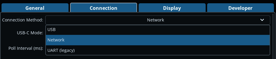
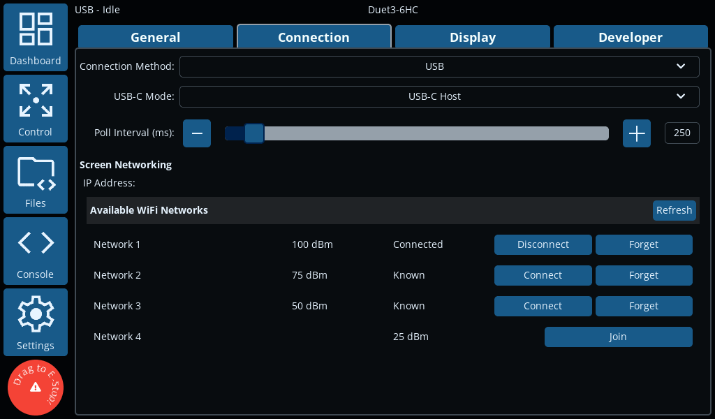 The Connection tab configures which port to use to connect to the Duet mainboard (USB, WiFi or UART).
If WiFi is selected, it will search for WiFi SSIDs and show a list to connect to. The DuetScreen keeps a list of remembered WiFi SSIDs for easy connection. Once connected, enter the Duet IP address and password (if necessary) to connect.
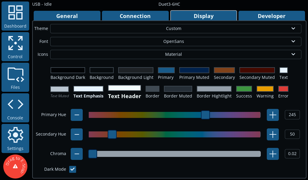 The Display tab provides options for the customising the display. There are a number of different themes, and options for changing the fonts and the icon set.
Using the "Custom" theme, you can also change the primary and secondary colour palette.
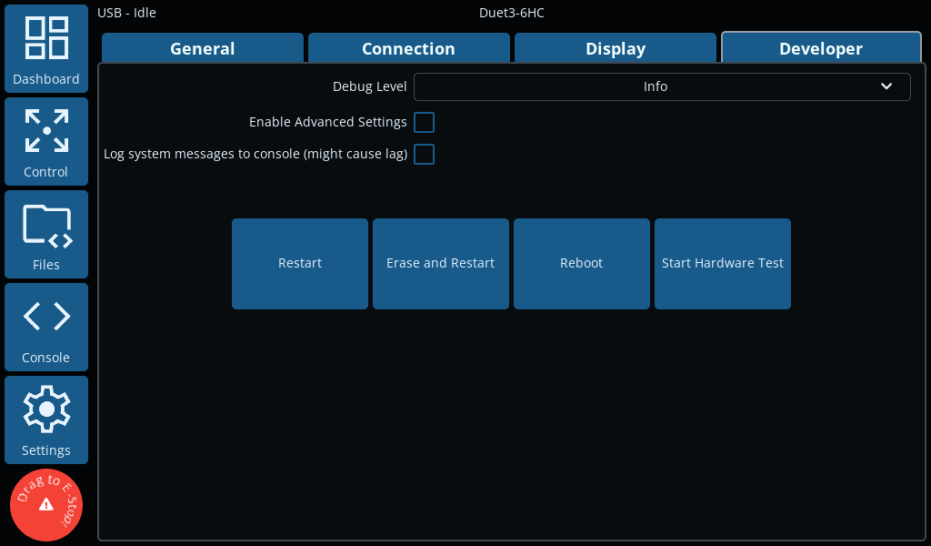 The Developer tab provides some advanced options for debugging etc.
¶ DuetScreen Software
¶ Writing DuetScreen Software to the SD card
-
Download the latest
sdcard.imgfrom the release page on Github. -
There are multiple programs to write an image file to an SD card:
- We recommend using the Raspberry Pi Imager, which has versions for Windows, MacOS, Linux and Raspberry Pi.
- or use balenaEtcher on Windows, Linux and MacOS
- or use
ddon Linux and MacOS
sudo dd if=sdcard.img of=/dev/sd# bs=4M -
Insert the microSD card into the DuetScreen and power it on.
¶ Updating DuetScreen
Several methods are available to update the DuetScreen.
Occasionally, an update may require the whole microSD card to be reflashed. This will be indicated in the release notes.
In this case, follow the instructions in the Flashing a new DuetScreen section above.
The (DuetScreen.tar.gz) will be available with all releases that do not require a full SD card image reflash.
¶ Using the GUI
- Copy the update file (
DuetScreen.tar.gz) to the root directory of a USB flash drive. - Insert the USB flash drive into the DuetScreen.
- In the GUI you will be prompted to update the DuetScreen.
- If the update is successful, the DuetScreen will automatically reboot. This will appear as a brief flash and the GUI will return to the Dashboard screen.
- The update will create an empty file called
upgradedin the root directory of the USB flash drive. This file is used to indicate that the update was successful.
¶ Force Update
- If the GUI is not working, you can force an update by renaming the update file to
update.tar.gzand placing it in the root directory of the USB flash drive OR microSD card. - Insert the USB flash drive or microSD card into the DuetScreen.
- (If using a microSD card) Power on the DuetScreen and it will automatically update.
- The update will have succeeded if the
update.tar.gzfile is removed from the root directory of the flash drive or microSD card.
¶ Fallback
- If the DuetScreen is still not working, you will have to reflash the microSD card with the latest image, see Flashing a new DuetScreen above.
¶ Version History
- No significant changes from v0.3
- Change non required connectors to DNP
- Initial internal development version