¶ Introduction
Duet3D filament monitors sense filament movement and so can indicate a that filament has run out, jammed or has been ground away in the extruder. This is the magnetic filament monitor version, so called because it uses a rotating magnet to very accurately detect movement.
Note the assembled version of the filament monitor works with 1.75mm filament, and the housing designs supplied by Duet3D for the kit version are similarily for 1.75mm filament. It is possible to design your own housing, or use one from the community for 2.85mm filament.
¶ How it works
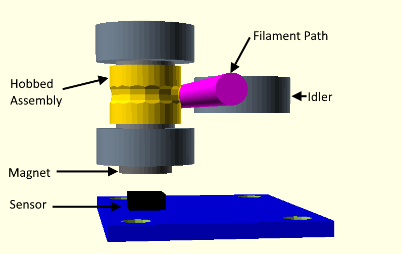
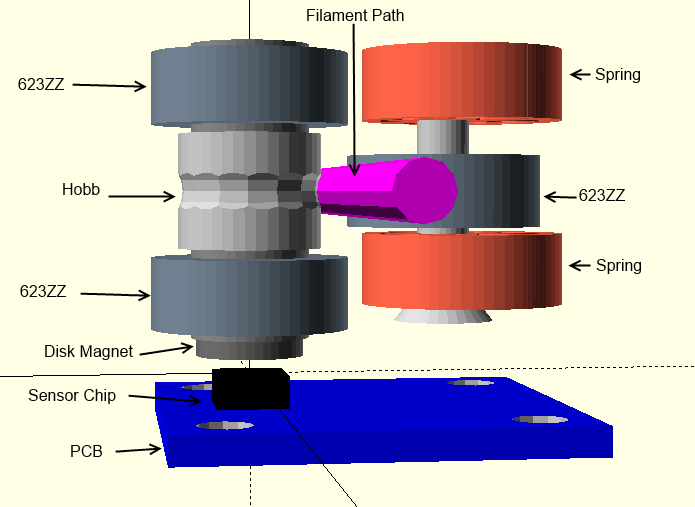
The filament monitor consists of a PCB which senses the rotation of a diametrically magnetised magnet. That magnet is in turn rotated by the filament motion via a hobbed part. The angle is reported to the Duet (see section on Technical details for how this is done). This diagram shows the general principle.
¶ Hardware
¶ Hardware specification
| Processor | ATTINY44A |
| Comms | single wire protocol designed for compatibility with Duet 2 endstop inputs and Duet 3 IO connectors |
| Magnetic Encoder | AS5601 |
| Input power voltage | 3.3V (5V compatible with a drillable via) |
| Maximum ambient temperature | 85°C |
This comprises the same components as the kit, fully assembled into a MJF printed housing
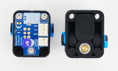
The assembled version uses v3 hardware
¶ Contents
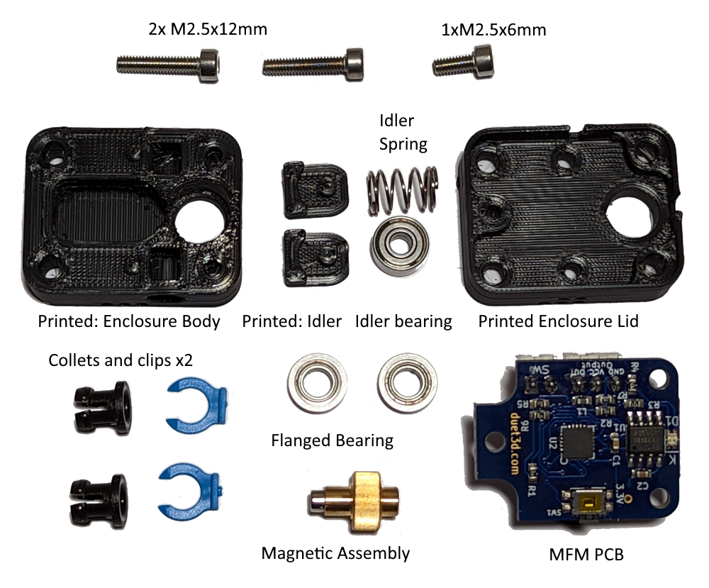
The housing consists of:
- The main part that carries the hobbed assembly, idler, collets and constrains the filament path.
- A lid that mounts the PCB a set distance from the magnet.
The printed parts are not supplied; the housing models are available on Github here and should be printed with a layer height of 0.2mm (including the first layer). This will ensure the correct distance between the magnet and the sensor PCB.
There are two versions of the body stl part, 1 with clearance M3 holes and one with holes sized for the M3 screws to tap into. Print the part that fits your mounting plan.
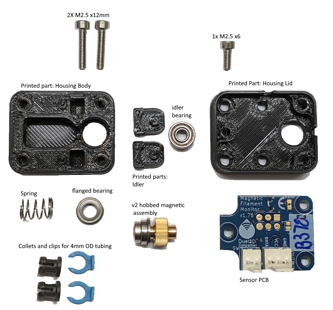
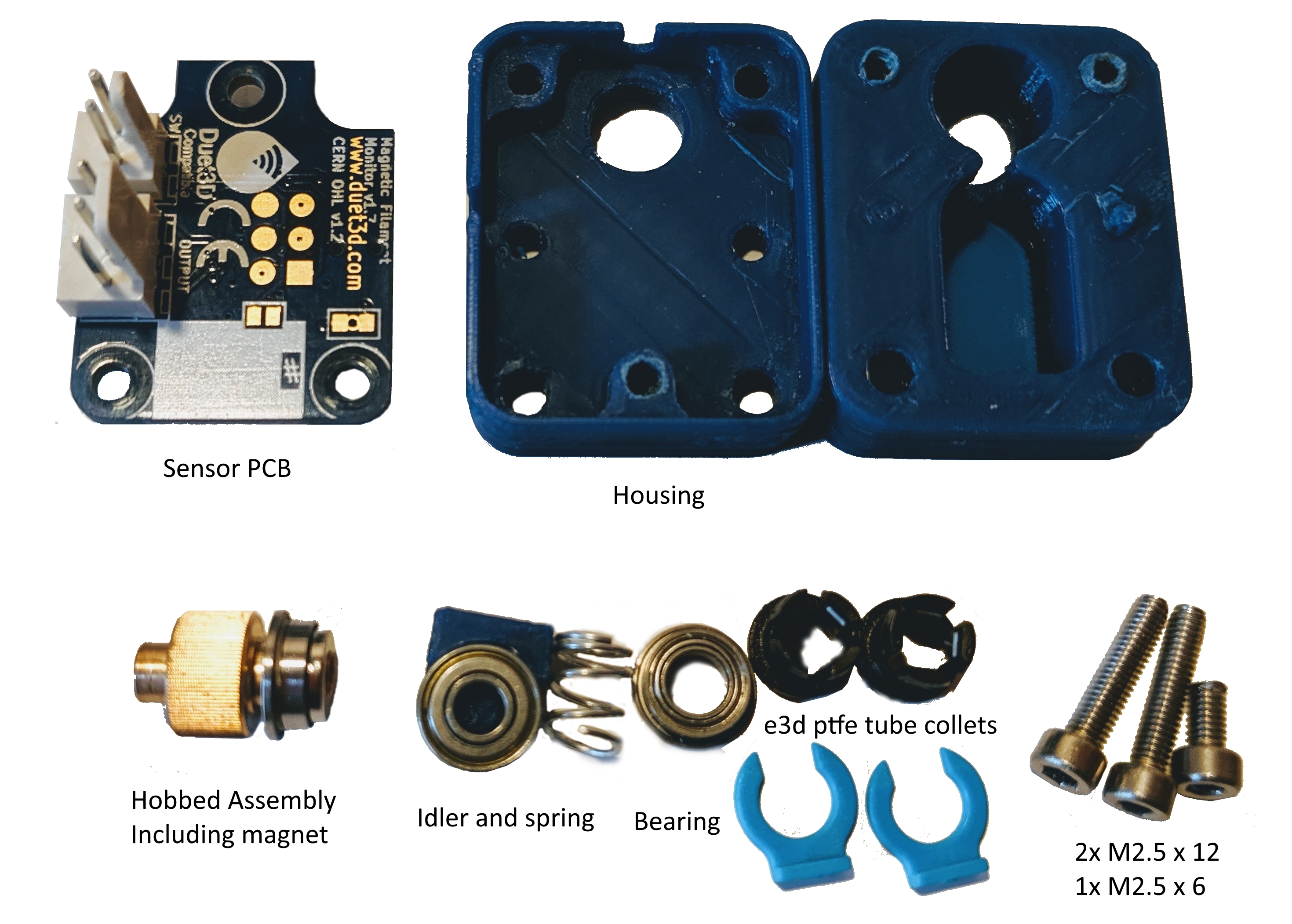
The v1 housing can be 3d printed using an FDM printer using a fairly high resolution (e.g. 0.1 layer height); however some tweaking will be required to get the magnet distance just right.
CAD models of the housing are available on our GitHub.
¶ Hobbed assembly
This consists of a custom machined hobbed part, and a 3mm diametrically magnetised magnet. Together with the idler this acts to closely couple the movement of the magnet to the movement of the filament.
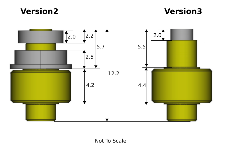
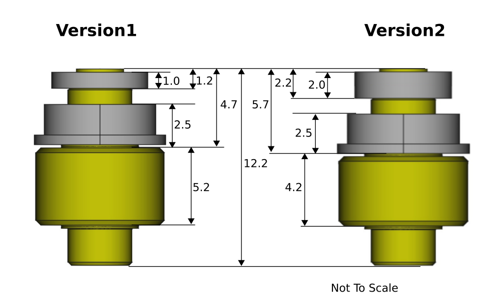
The v3 hobbed assembly has a rod magnet as opposed to the ring magnet used in the v2.0 and v1.0 MFMs
This consists of a custom machined hobbed part, a bearing and a 6mm diametrically magnetised magnet. Together with the idler this acts to closely couple the movement of the magnet to the movement of the filament.
The v2 hobbed assembly has a 2mm thick magnet (vs the 1mm thick magnet in the v1 design).
¶ Idler assembly
This consists of a bearing carrier in two parts that can be 3d printed at 0.2mm layer height, an idler bearing and a spring.
¶ Collets and clips
These hold 4mm OD PTFE tubing in both sides of the filament monitor. The tubing ensures the filament runs along the correct path and should be fully inserted into the filament monitor on both sides and locked into place using the collet clips.
¶ PCB
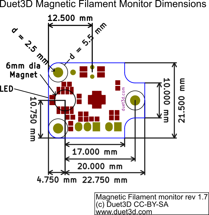
The filament monitor PCB can be used to detect the movement of any appropriate diametrically magnetised magnet. It can be used in custom extruder designs, the diagram below shows the critical dimensions.
¶ PCB Dimensions
Note there a multiple revisions of the v1.7 and v3.0 PCB but the critical dimensions have not changed.
¶ Assembly
Before starting ensure the printed parts are free from stringing and that filament passes through the filament path. the filament path may need to be reamed out with a 1.8mm drill bit.
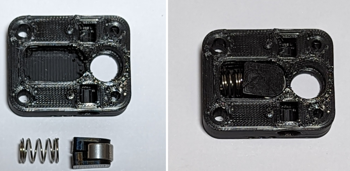
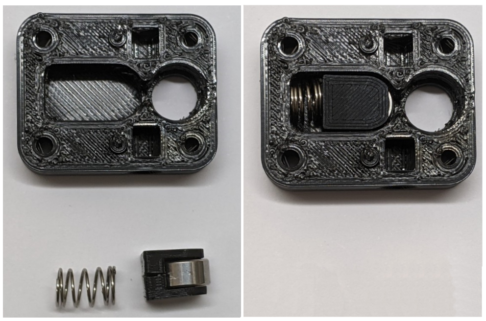
Install the idler carriers, idler bearing and spring.
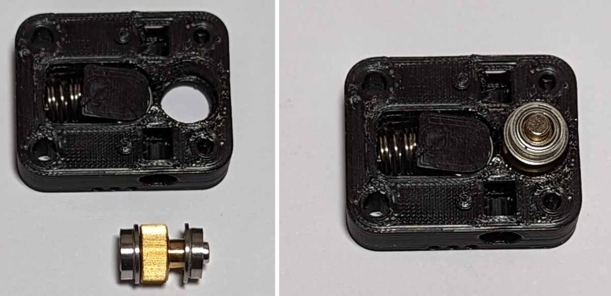
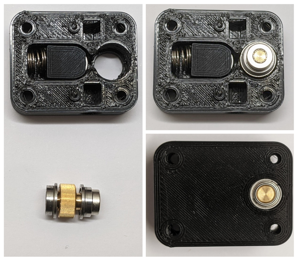
Place the flanged bearing on the magnetic assembly and then fit in the body as shown. Ensure the bearing is seated properly
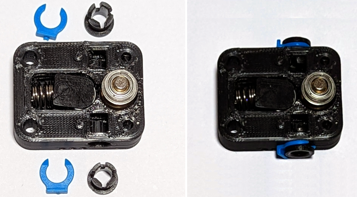
Insert the collets and collet clips.
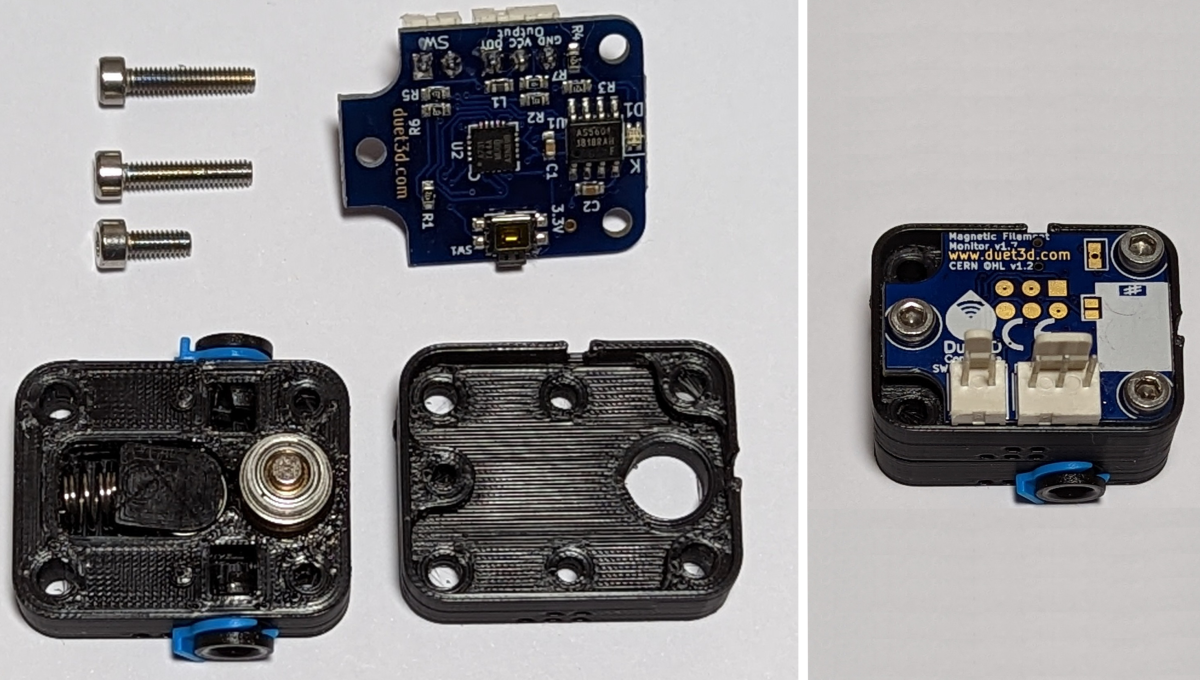
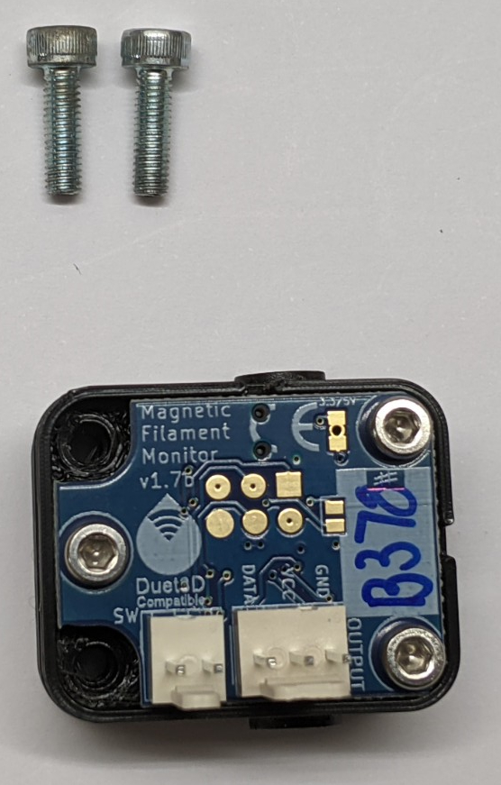
Place the lid on top. It is usual for the magnet to cause the lid to lift slightly until the PCB is screwed into place. Screw the PCB in place as showing. note the two 12mm long M2.5 screws go to the left as show in this image, the single 6mm M2.5 screw goes to the right.
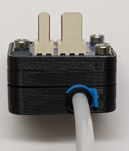
If the MFM will be mounted directly above an extruder, supported only with the PTFE tube then use M3x 10 screws (not supplied) to complete the assembly. If the MFM will be screwed into a mounting plate then use appropriate length M3 screws for the chosen mounting method.
Mount using PTFE tube to guide the filament in and out of the filament monitor.
Before starting ensure the printed parts are free from stringing and that filament passes through the filament path. the filament path may need to be reamed out with a 1.8mm drill bit.
Install the idler carriers, idler bearing and spring.
Place the flanged bearing on the magnetic assembly and then fit in the body as shown. Ensure the bearing is seated properly
Place the lid on top. It is usual for the magnet to cause the lid to lift slightly until the PCB is screwed into place. Screw the PCB in place as showing. note the two 12mm long M2.5 screws go to the left as show in this image, the single 6mm M2.5 screw goes to the right.
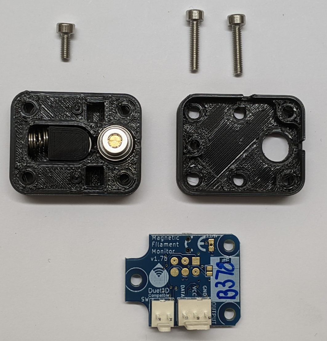
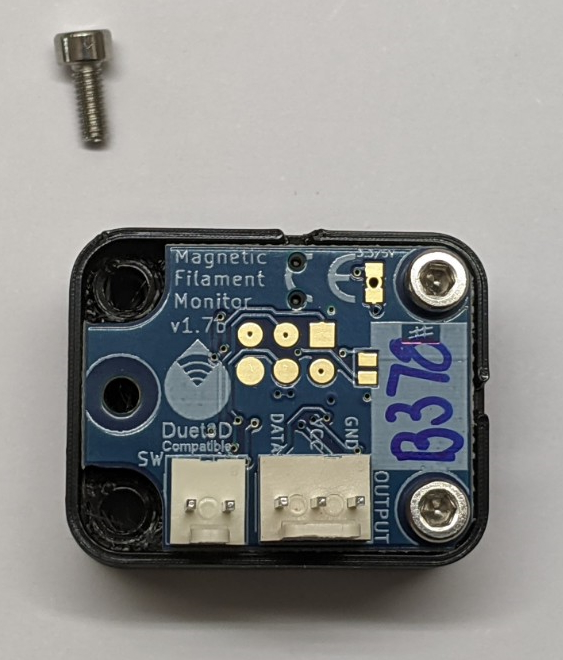
Insert the collets and collet clips.

If the MFM will be mounted directly above an extruder, supported only with the PTFE tube then use M3x 10 screws (not supplied) to complete the assembly. If the MFM will be screwed into a mounting plate then use appropriate length M3 screws for the chosen mounting method.

Ensure the bearing in the main housing is seated properly and installer the idler carrier, idler bearing and spring.
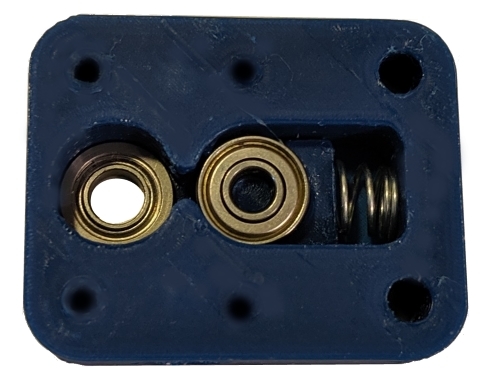
Place the hobbed assembly on the bearing and place the lid on top. It is usual for the magnet to cause the lid to lift slightly until the PCB is screwed into place.
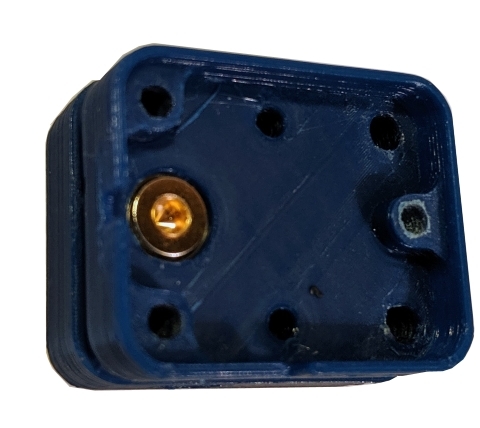
Screw the PCB in place as showing. note the two 12mm long M2.5 screws go to the left as show in this image, the single 6mm M2.5 screw goes to the right.
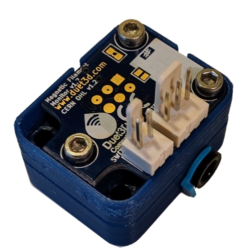
Insert the collets and collet clips. Note that they are not secure in the housing until PTFE tube is inserted.
¶ Mounting
The monitor can be installed either before or after the extruder. It can mount directly onto the PTFE filament guide or bowden tube, held in place by the collets and collet clips. Alternatively there are two M3 holes in the housing to allow it to be screwed onto a flat surface.
Note: The filament monitor needs to be close to the input or output of the extruder to get accurate results otherwise the flexing of the filament withing the feed/bowden tubes will reduce the accuracy of the readings
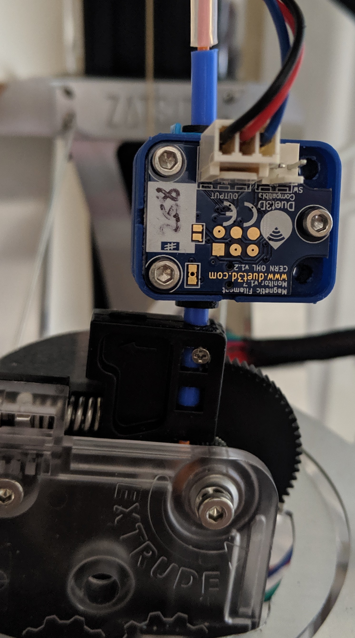
It is important that the PTFE guide tube does not move during retraction and the filament path is constrained through the monitor so retractions are measured properly.
On systems that use a bowden tube it is also possible to mount the filament monitor after the extruder. In this case filament out will not be detected until the end of the filament is in the extruder. The second two-pin header on the PCB is connected a separate filament sensing switch if you want to detect filament out before the extruder, but detect movement after the extruder.
Note that when mounting after the extruder, ensure that the dust from the entruder teeth on the filament does not end up in the MFM as it can clogg the hobbed teeth in the MFM causing it to slip.
¶ 3D Model
STEP file is available on Github
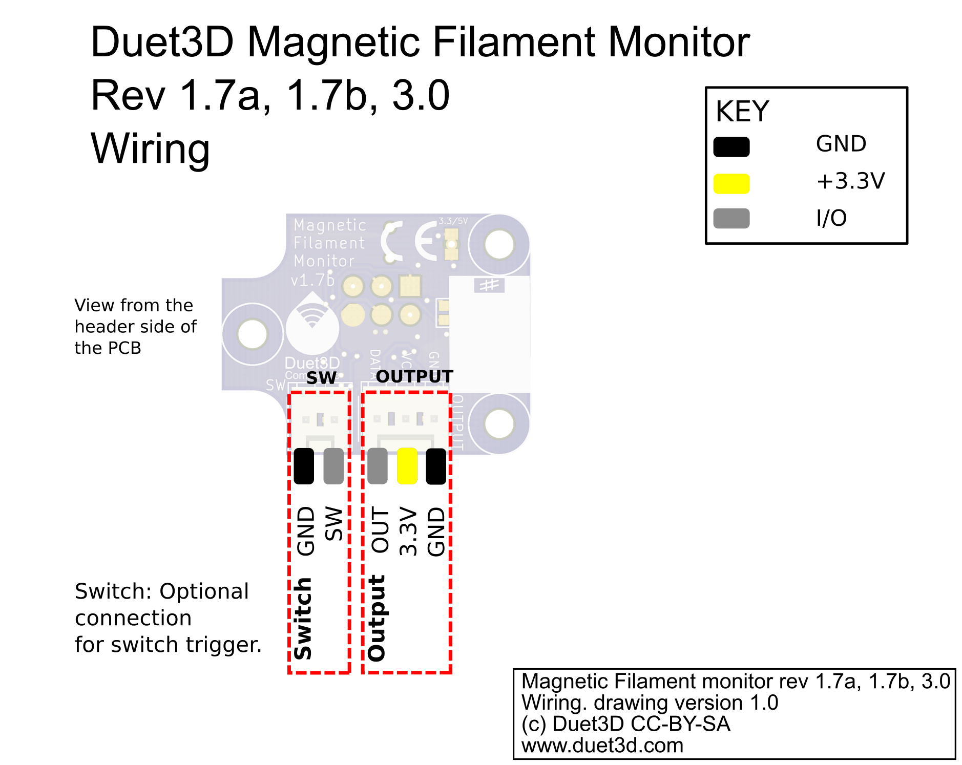
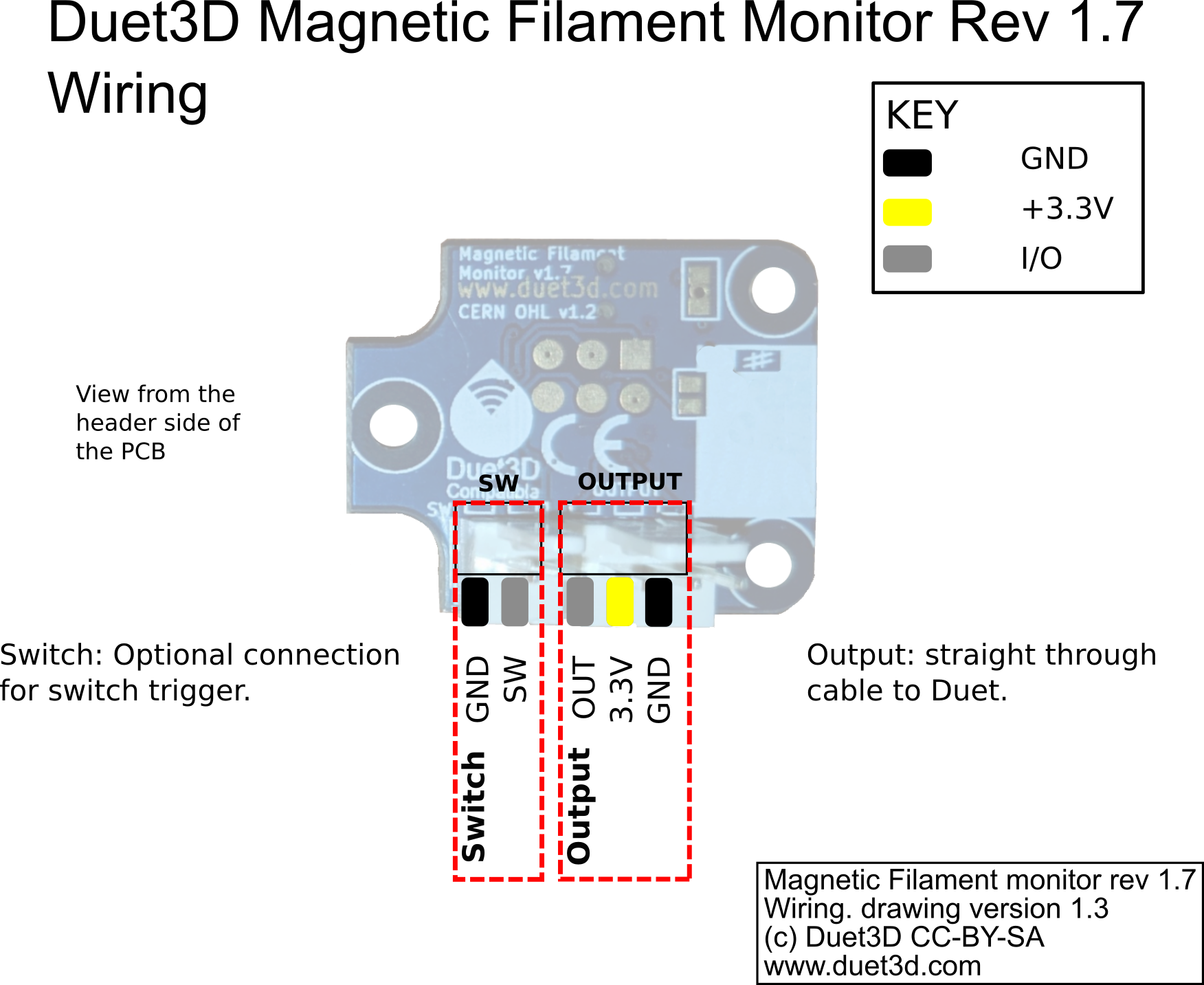
¶ Wiring
Note: on board revision v1.7a and later, the 'Switch' and 'Output' header is rotated 180 degrees, ie the connector tab is on the outside edge, compared with v1.7.
¶ 5V Operation
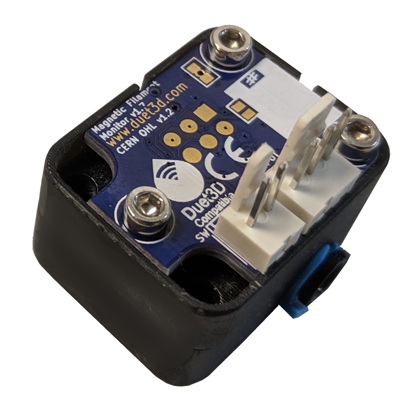
It is possible to modify the Filament monitor PCB to connect to a controller that uses 5V logic. To do this use a small drill bit to carefully remove the connection between the two pads that is made with the ring of the through hole between the pads. Test that the pads are actually disconnected by checking that there is no continuity between them with a voltmeter.
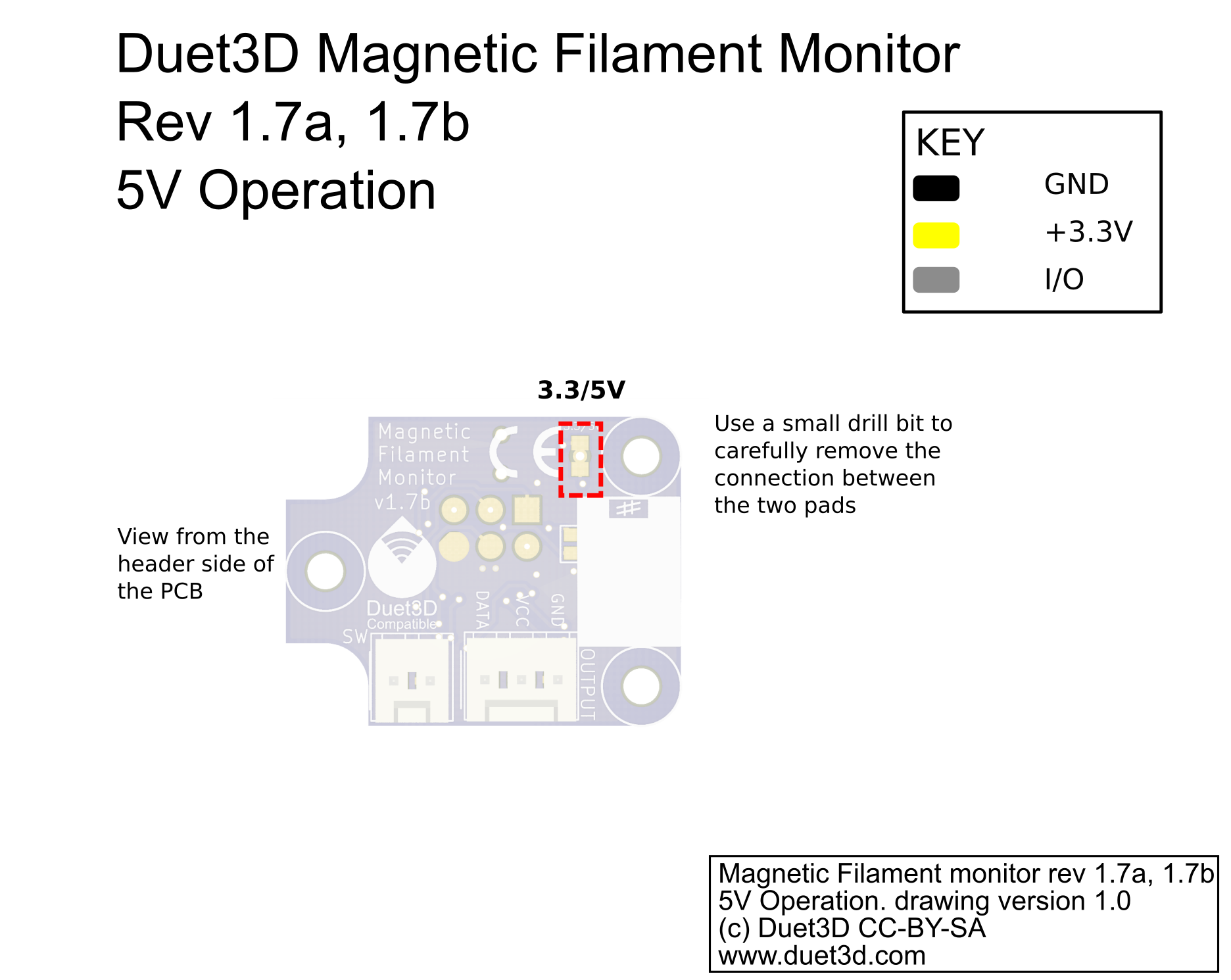
This image shows PCB v1.7b, the process is the same for v3.0. 1.7a and 1.7
¶ Connecting and configuration
For connecting, firmware configuration, commissioning and troubleshooting, see Connecting and configuring filament-out sensors.
¶ Technical details
The filament monitor sends 16-bit words to the Duet. When the data is changing (normally because the filament is moving), one word is sent every 40ms. When the data isn't changing, one word is sent every 500ms.
Bit 15 of each word is 1 if the filament monitor is in an error state, 0 otherwise. Bit 14 is the state of the optional filament present switch: 1 if the input is high (meaning no filament is present) and 0 if it is low. However, the beta filament monitor firmware does not implement bits 14 and 15, they are always sent as 0.
Bits 0-9 represent the magnet angle measured in units of 1/1024 of a complete rotation.
The 16 bits are sent using a self-clocking protocol as follows. The nominal bit time is 1ms but the Duet firmware allows a reasonable tolerance because the filament monitor clock source is the internal R-C oscillator in the microcontroller, so its speed is somewhat variable.
- Idle state: the line must be be at 0 for at least 8 bit times
- Start bits: 1 followed by 0
- Data bits 15, 14, 13, 12
- Stuffing bit (inverse of bit 12)
- Data bits 11,10,9,8
- Stuffing bit (inverse of bit 8)
- Data bits 7,6,5,4
- Stuffing bit (inverse of bit 4)
- Data bits 3,2,1,0
- Stuffing bit (inverse of bit 0)
- After the last stuffing bit, the line returns to 0 until the next start bit.
¶ Flashing the firmware
The filament monitor will come with firmware flashed and tested. The only reason to flash firmware is to upgrade the firmware or install custom firmware.
The Firmware binaries and source code are available on Github here
All version 1.7 and later monitors use Release 44a
An ISP programmer and pogo pin connections are needed to flash the firmware. There are many options available, e.g:
For the pogo pins:
The pads are the standard ISP pinout;
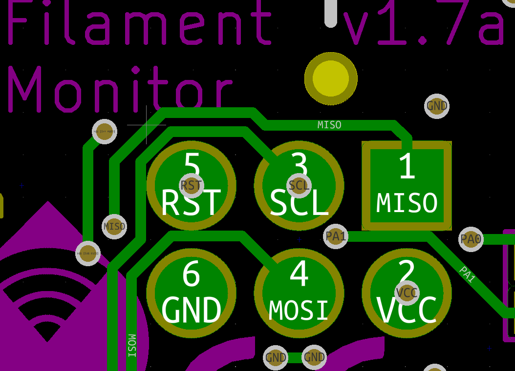
To write the firmware file to the filament monitor a program called avrdude is used (there are other avr programming softwares available, for example Atmel Studio). Once installed the command line is used to flash the firmware:
C:\avrdude\avrdude -p t44 -c usbtiny -U flash:w:"G:\Rotating Magnet\firmware\version_3\FilamentSensor.elf":e
obviously change the paths to wherever you put AVR dude and the firmware binary.
The fuses should be set correctly on the monitor but if they are not the following command sets them correctly:
C:\avrdude\avrdude -p t44 -c usbtiny -U lfuse:w:0xe2:m -U hfuse:w:0xdf:m -U efuse:w:0xff:m
¶ Revisions
Changes to the magnetic assembly and housing design. No change to the PCB design:
- Magnetic assembly changed from a ring magnet to a rod magnet.
- Enclosure modified slightly to accommodate new magnetic assembly.
- PCB silkscreen changed from 1.7b to 3.0 but PCB otherwise unchanged.
A minor update with the following changes:
- minor changes to passive component sizes, no functional changes.
A minor update with the following changes:
- SW header pinout is reversed to reduce the likely-hood of damage if the output connector is accidentally plugged into it.
- the OUT header is fitted the other way around (but the pinout is unchanged).
A redesign with the following changes:
- A custom hobbed part that includes a captive bearing and the magnet swaged on to form a secure a repeatable mounting.
- PCB has been made smaller and adapted for easier mounting.
- 2 part housing that can be printed using an an SLS/resin printing, machined or injection moulded. It is also possible to print it using an FDM process but layer heights should be tuned to achieve the correct Magnet/sensor offset..
- Idler containing a spring and bearing
Note: the firmware on revision 1.7 is reported by the Duet as version 2.0 for both the magnetic and laser filament monitors
This is the original version, only produced in small numbers.
The beta PCBs have these dimensions andkey component locations:
Beta Magnetic Filament Monitor PCB dimensions and Key Component Locations
Springs
The design uses 2 3D printable springs, so far good results have been achieved printing these in Ninjaflex but similar flexible filament should also work
Enclosure
The current enclosure design is split into two parts, one part holds the mechanical components that cause the moving filament to rotate the magnet. The second part holds the PCB in line with the magnet.
Mount
Different mounts will be required to mount the sensor to different extruders, effectors etc. An example for mounting to a big box Idex is shown in the documentation right now.
Download
The OpenSCAD source file and STLs are available on Youmagine: https://www.youmagine.com/designs/duet3d-filament-monitor
The following instructions are for the standard hardware design used for the Beta test programme. Alternative housing designs and potentially ways of coupling filament movement to magnet rotation are possible. Please see the forum thread for further discussion.
- Assemble the hobb, bearings and magnet:
| Component | Quantity | Notes |
|---|---|---|
| M3x16 with magnet fitted | 1 | Supplied assembled |
| 623ZZ bearing | 2 | |
| Hobbed insert | 1 | |
| M3 full net | 1 | Held in place with a drop of superglue/thread lock |
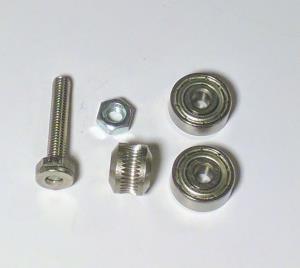
Assemble as shown in the picture, the full nut is held in place with a drop of superglue or threadlock.
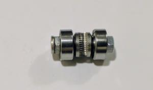
- Assemble the idler bearing and springs:
| Component | Quantity | Notes |
|---|---|---|
| M3x16 socket cap screw | 1 | |
| 623ZZ bearing | 1 | |
| 3d printed spring | 2 |
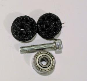
Assemble as shown in the picture, the 3d printed rubber springs hold the idler bearing in place, no nut is required.
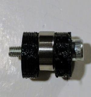
- Print the housing and mounting parts, gather the remaining parts:
| Component | Quantity | Notes |
|---|---|---|
| Idler Assembly | 1 | previously assembled |
| Hobb Assembly | 1 | previously assembled |
| Mechanical enclosure | 1 | 3d printed |
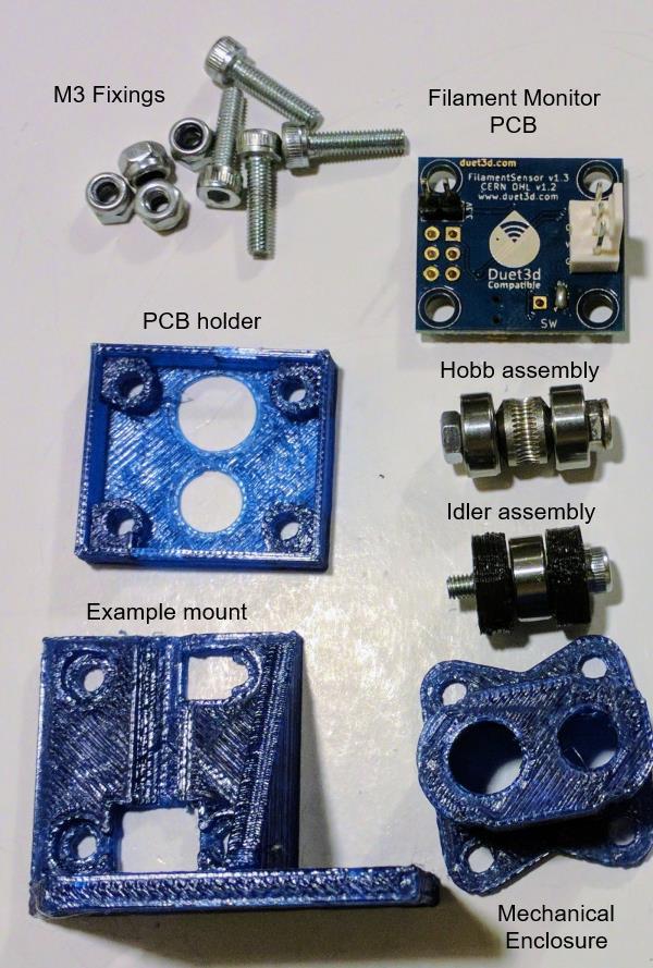
- Fit the idler spring and hobb assembly into the mechanical enclosure.
| Component | Quantity | Notes |
|---|---|---|
| Mechanical enclosure | 1 | previously assembled |
| PCB | 1 | |
| PCB holder | 1 | 3d printed |
| mount | 1 | 3d printed |
The Idler assembly fits in the larger hole in the mechanical enclosure, this should be fitted first and the 3d printed rubber springs will be tight. The off center springs should be oriented the same way, holding the idler bearing towards the hobb.
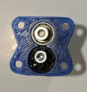
Check that the hobbed section and the idler pulley align with the filament hole:
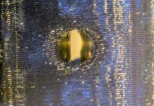
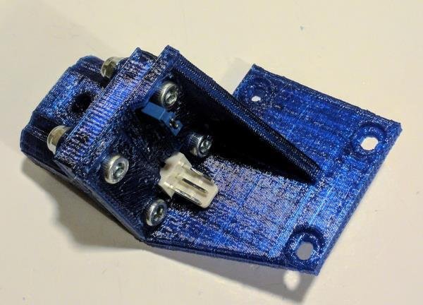
- Complete the assembly with the PCB, PCB holder, mount, M3 SCS and nylock nuts. Note the magnet should sit approximately 0.5mm above the sensor, the PCB holder hole sizes match
- Mount as required.
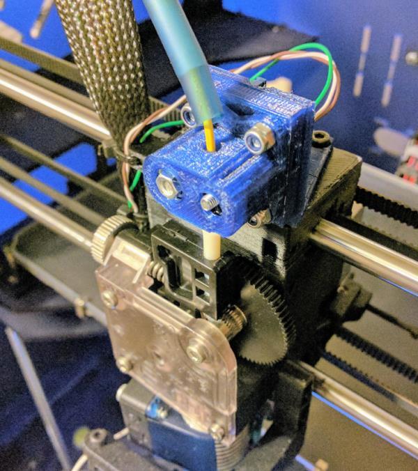
Note different mount designs will be required to fit relative to different extruders. This is an example with it mounted on a BigBox Idex.
