¶ Introduction
The DueX5 is an expansion boards for the Duet 2 Wifi and Ethernet. It provides up to 5 additional stepper, heater etc channels to allow for 3D printers or other machines with more axis, multiple drivers per axis, tool changers etc.
The DueX2 (now discontinued) was a 2 driver version of the Duex5 - the same PCB with 3 of the drivers not populated. These instructions still mention the DueX2 in some places and from v0.11 of the DueX5 it is possible to use jumpers to make a DueX5 appear like a DueX2 to allow external drivers to be used for Drivers 7, 8 and 9.
In the following instructions given for the DueX5 apply equally to the DueX2 except where noted.
¶ Features
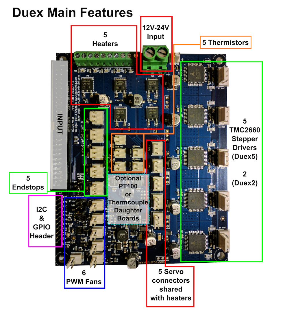
The DueX2 and DueX5 are based on the same PCB with 3 channels of steppers, heaters fans etc not populated on the DueX2 to save costs.
¶ Hardware specification
| DueX5 | DueX2 v0.8a and newer | DueX2 v0.8 and older | |
|---|---|---|---|
| On-board Stepper drivers | 5 x TMC2660 | 2 x TMC2660 | |
| Stepper driver features | Up to 2.4A peak current, up to x256 microstepping, optional x16 interpolation on x16 microstepping, stall detection | ||
| Heater outputs | 5 x extruder heater (up to 6A each) | 2 x extruder heater (up to 6A each) | |
| Thermistor/PT1000 inputs | 5, optimised for 100k thermistors, can support PT1000 sensors with reduced accuracy | 2, optimised for 100k thermistors, can support PT1000 sensors with reduced accuracy | |
| Fan outputs | 6 PWM controlled outputs (from board revision v0.8) for fans and/or LEDs, with voltage selectable between 12V, 5V or VIN | ||
| Inputs/Outputs | 5 on-board endstop inputs with 3.3V/5V voltage selection, 4 uncommitted general purpose I/O pins. | 2 on-board inputs with 3.3V/5V voltage selection, 4 uncommitted general purpose I/O pins. | |
| Endstop inputs | See under Inputs/Outputs | ||
| Servo outputs | 5, with 5V power and 5V signal levels. Control channel shared with heaters, so you can use unused heater channels to drive servos. | 2, with 5V power and 5V signal levels. Control channel shared with heaters, so you can use unused heater channels to drive servos. | |
| Endstop status LEDs | Yes | ||
| PT100 and thermocouple daughter board support | 2 boards (4 channels) | ||
¶ Operating limits
| Stepper drivers | Up to 2.4A peak current |
| Heater outputs | 2 (DueX2) or 5 (DueX5) x extruder heaters up to 6A each |
| Input power voltage | 11V to 25V1 |
| Input connector rated current | 25A maximum |
| Inputs/Outputs | Endstop pins are 5V-tolerant |
| Fuse | 7.5A for stepper drivers, extruder heaters and fans |
| 12V current limit | 2A total for fans and 12V header (when internal 12V is selected) |
| 5V current limit | (supplied by connected Duet 2) 1A total on PWM pins and fans (when internal 5V is selected) |
| External 5V current limit | 3A maximum total peak current, 2A continuous total on PWM pins and fans (when external 5V is selected) |
| Maximum ambient temperature | 70°C |
Note: At high currents, it is essential to use either ferrules or solid core wire with the terminal blocks on the Duet 2 and DueX2/5.
1 The maximum recommended power input voltage is 25V. This is a permanent limitation, because the TMC2660 drivers are rated at 30V when supplying power to motors.
¶ Firmware notes
The DueX2 and DueX5 are supported in firmware 1.16 and later. You must upgrade the firmware on your Duet 2 WiFi/Ethernet if you are using an earlier version.
¶ Compatibility
The DueX2 and DueX5 are expansion boards for the Duet 2 Wifi and Ethernet. These expansion boards are not compatible with the Duet 0.6 or Duet 0.8.5
¶ Open Source
Importantly Duets are Open:
- The Duets are Open Hardware, see our license here
- All hardware source files are available on Github.
- Both the Duet Web Control web interface and RepRapFirmware are Open Source Software with source files available and actively maintained, see Contributing to development for more information.
- The Duet hardware and RepRapFirmware are built with Open tools: designed in KiCad and Eclipse using open tools means the barrier to getting involved is as low as possible.
¶ Physical properties
¶ Dimensions
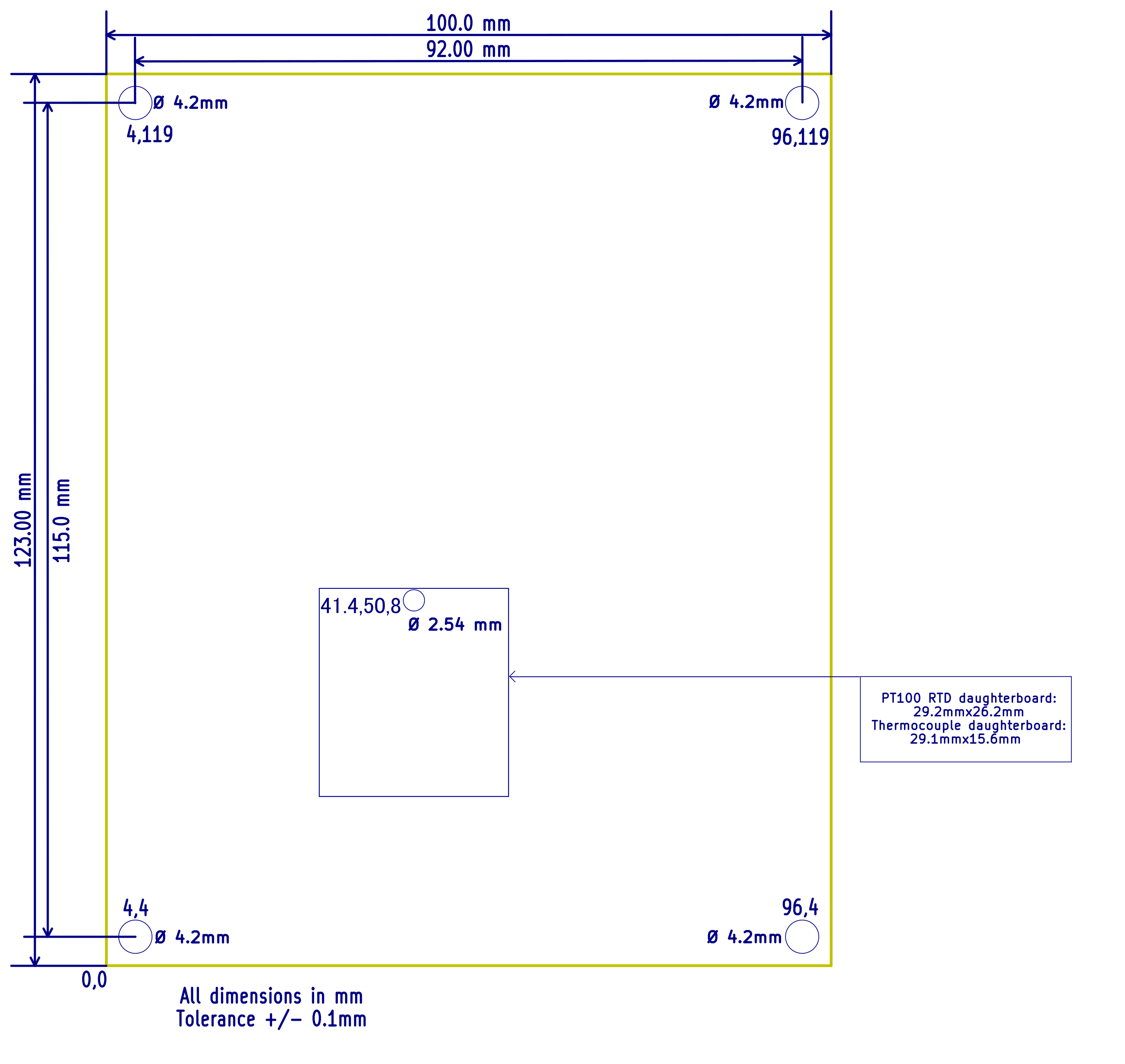
The DueX2 and DueX5 is dimensionally the same as Duet 2 WiFi/Ethernet.
¶ Mounting
The DueX is designed to be mounted back-to-back with the Duet 2 using long M4 screws and spacers. Alternatively, it can be mounted adjacent to the Duet 2 with the expansion connectors on the two boards next to each other.
It is also possible to mount the two boards side-by side with power connectors next to each other, but in this case the 50-way ribbon cable needs to be at least 200mm long instead of the standard 100mm.
¶ Cooling
As with the Duet 2, the stepper motor drivers are cooled via the PCB. To improve cooling, you can use a fan to blow air over the PCB, especially the underside. When the Duet 2 and DueX are mounted back to back, you can use a single fan to blow air between the two boards.
¶ 3D models
The DueX v0.11 CAD file is available on the Duet3D Github repository here (download the STEP file)
Morten Nielsen has also shared a model of the earlier versions, available here.
¶ Using a DueX5 with External drivers
The DueX5 can be used to control up to three external drivers, by disabling the on-board driver chips for drives 7, 8 and 9, and using the Driver 7, 8 and 9 external connector.
There are two modifications to do, both of which use jumpers on the DueX5 v0.11, but use drillable/solderable jumpers on the DueX5 v0.10 PCB. The first modification is to change the board ID so that the Duet 2 thinks a DueX2 is attached. This is done to stop the on-board stepper drivers reporting errors. The second is to disable the onboard drivers so that external driver connectors can be used.
Note that the step, direction and enable signalling is 3.3V.
If you only want to control one or two external steppers, and keep four or three internal drivers working, don't switch the board to DueX2 mode. Then, disable the internal driver by removing the jumper (v0.11) or cutting the trace (v0.10). You will get driver errors when you disable the internal driver, but you can silence these by adding M569 P[driver number] R-1 to config.g. You will not be able to use the Enable signal on the external driver, but step and direction pins will still control it.
¶ DueX5 v0.11 with External Drivers
Caution! The signals on D7, D8 and D9 are all at 3.3V. The Step, Dir and Enable signals are an extension of the signals coming from the Duet over the 2x25 expansion header, with no additional voltage translation or protection. The Stop signal is a duplication of the one found on the corresponding endstop connection on the Duex. If you want to use them take the same precautions as if you were plugging directly into the expansion header of the Duet.
Remove the jumper that is labelled "open for DueX2"
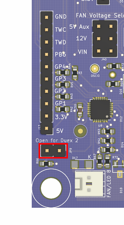
Note that the "cut for DueX0" jumper is not supported in firmware yet.
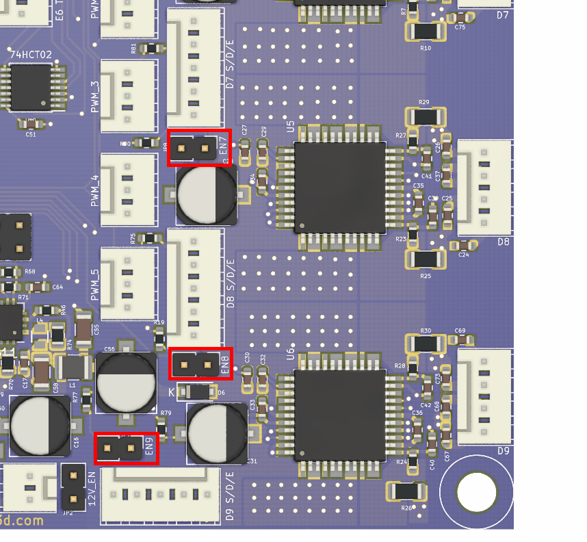
Remove the enable jumpers for D7, D8 and D9. Connect the external driver to the 'D# S/D/E' header.
¶ DueX5 v0.10 with External Drivers
There is a jumper marked "Cut for DueX2" on the underside of the DueX5 v0.10 board:
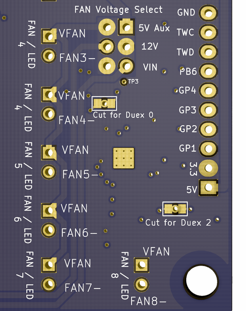
To break the circuit to make the DueX5 appear to be a DueX2, gently remove the copper ring of the jumper using a 1mm drill bit and confirm its removal by testing between the two pads using a multi-meter; there should be no connection.
Note that the "cut for DueX0" jumper is not supported in firmware yet.
From version 0.10 it is possible to disable the internal drivers on the DueX5 so external drivers can be used.
To do this there are 5 small drill-able solder jumpers on the underside of the board labelled EN5 to EN9. The image below shows jumpers EN5 and EN6:
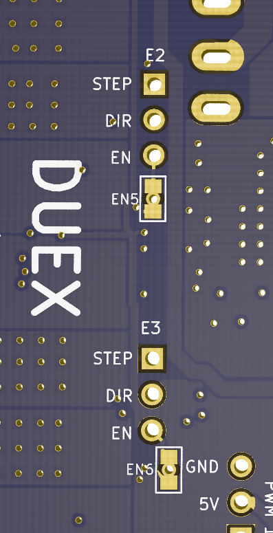
To disable the internal jumper, gently remove the copper ring of the jumper using a 1mm drill bit and confirm its removal by testing between the two pads using a multi-meter; there should be no connection.
Solder a 3-pin header to the 'E# STEP DIR EN' vias and connect the external driver.
¶ Physical connections
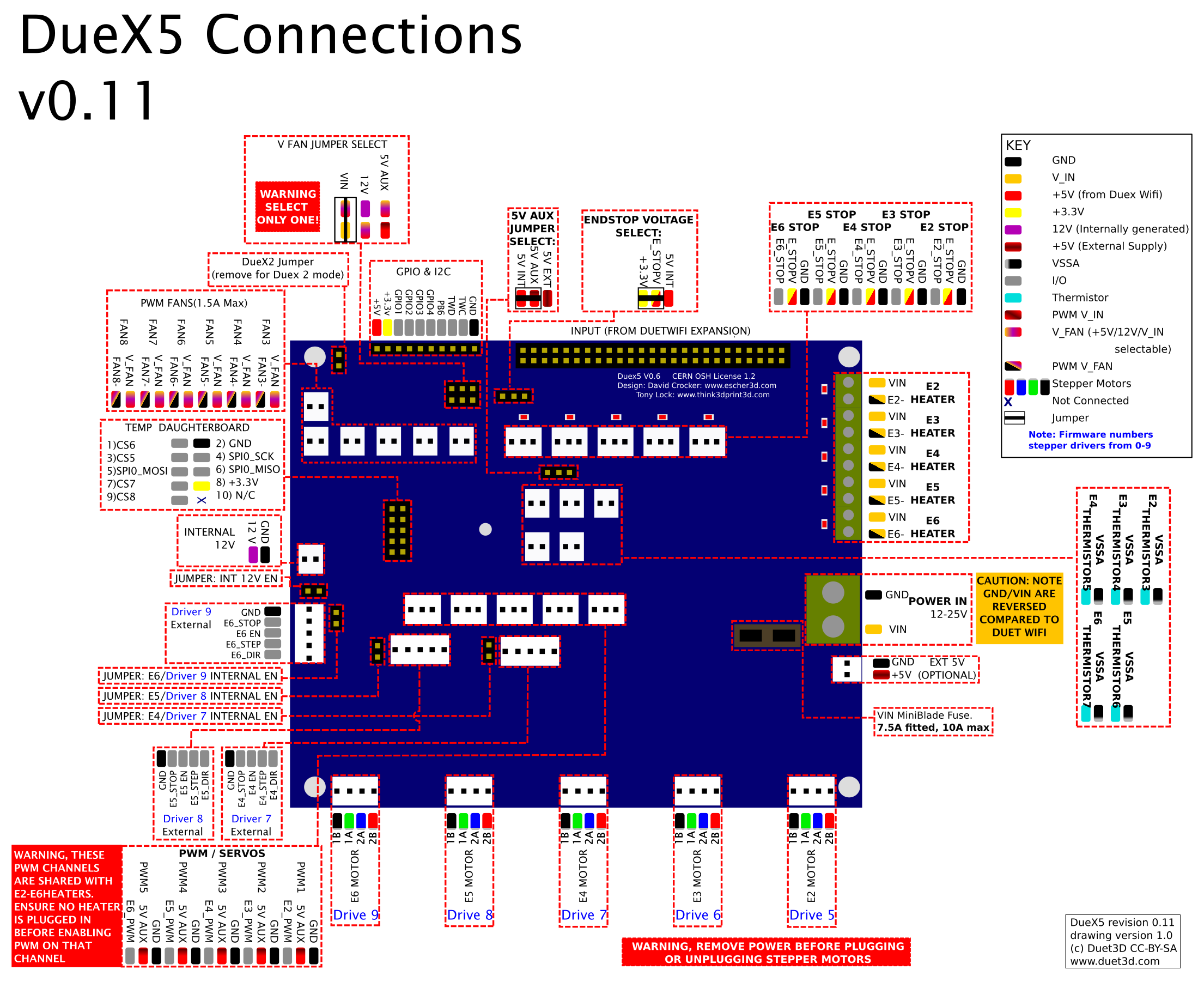
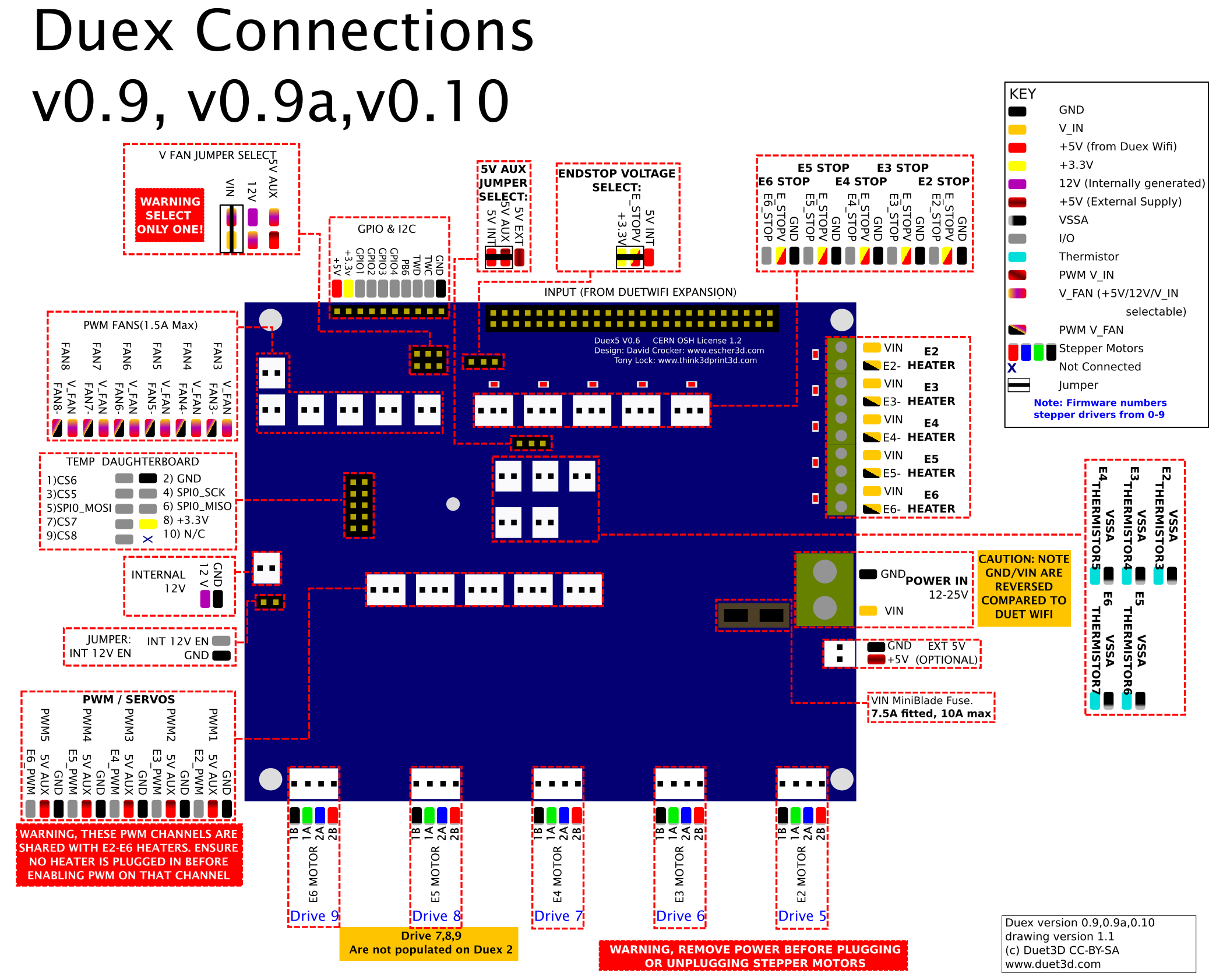
¶ Wiring diagram
For these revisions forward the only difference between the DueX2 and DueX5 is only two stepper drivers are populated on the DueX2.
The .svg version of this diagram is available on github.
Version 0.8 had a 6th fan MOSFET and Header added
For these revisions the DueX2 had only the first two stepper and heater channels populated, only 2 fan, heater and temperature channels populated, and only the first 3 servo channels are enabled (although all 5 headers may be populated).
Version 0.8 had a 6th fan MOSFET and Header added
¶ Description of connections
DueX boards provide the following connectors:
| Header | PCB label | Function |
|---|---|---|
| 1 x 2-way screw terminals, 6.35mm spacing | POWER IN, GND, VIN | two terminals for main VIN and GND. |
| 1 x 2-pin KK header | EXT 5V | Optional 5V external power input for powering servos, fans etc. Set the 5V AUX JUMPER SELECT jumper appropriately. |
| 5 x 4-pin KK headers | E2 MOTOR, E3 MOTOR, E4 MOTOR, E5 MOTOR, E6 MOTOR | Stepper motor connections. |
| 5 x 3-pin KK headers | PWM1, PWM2, PWM3, PWM4, PWM5 | 5V PWM headers for . 1A total max current on internal 5V, 2A total max current on external 5V. The PWM channels are shared with the heaters, DO NOT HAVE A HEATER PLUGGED INTO A CHANNEL YOU CONFIGURE FOR PWM. |
| 1 x 2-pin jumper | INT 12V EN | Jumper to enable onboard 12V regulator |
| 1 x 2-pin KK header | INTERNAL 12V | 12V header, for always-on fan or LEDs, for example. |
| 1 x 2x5 IDC connector | TEMP_DB | This is for connecting PT100 and thermocouple interface boards and/or other SPI connected devices |
| 6 x 2-pin KK headers | FAN3, FAN4, FAN5, FAN6, FAN7, FAN8 | 6 PWM-controlled fan connectors. Voltage selectable between 5V internal (1A max total), 5V external (2A max total), 12V internal (2A max total) or VIN (all fans together). |
| 3 x 2-pin jumpers | V FAN JUMPER SELECT | Selects voltage for PWM fans, between 5V (internally or externally supplied), 12V internal and VIN. |
| 1 x 10-pin header,open | GPIO & I2C | Includes 4 uncommitted general purpose I/O pins, +5V and +3.3V. |
| 1 x 3-pin jumper | 5V AUX JUMPER SELECT | Selects between using internal 5V (supplied by connected Duet 2 WiFi/Ethernet) or external 5V (supplied to EXT 5V header). |
| 1 x 3-pin jumper | ENDSTOP VOLTAGE SELECT | Selects between +3.3V and +5V for endstop pins. |
| 1 x 2x25 IDC connector | INPUT | Use the supplied 50-pin ribbon cable to connect the DueX to the host Duet 2 WiFi/Ethernet expansion connector. |
| 5 x 3-pin KK headers | E2 STOP, E3 STOP, E4 STOP, E5 STOP, E6 STOP | Input connectors for endstops |
| 5 x 2-way screw terminals, 3.5mm spacing | E2 HEATER, E3 HEATER, E4 HEATER, E5 HEATER, E6 HEATER | Intended for high current output, eg extruder heaters or fans. Maximum recommended current 6A each. Note that the overall current limit (7.5A fused) means full current through them all at the same time. If you connect high-current inductive loads to these outputs, you must use external flyback diodes. |
| 5 x 2-pin KK headers | E2_THERMISTOR3, E3_THERMISTOR4, E4_THERMISTOR5, E5_THERMISTOR6, E6_THERMISTOR7 | Connections for thermistor or PT1000 sensors |
¶ LED indications
LEDs are provided to indicate the following:
Heaters: Each heater from E2_HEATER to E6_HEATER has a red indicator LED. When lit, the heater is on.
Endstops: Each endstop from E2_STOP to E6_STOP has a red indicator LED. When lit, the endstop is closed.
¶ Pin names
| Label/pin on DueX PCB/wiring diagram | RRF3 Pin name (DueX) | Shared with (on Duet) |
|---|---|---|
| Heater outputs | ||
| E2 HEATER, E2-, PWM_1, E2_PWM | duex.e2heat, duex.pwm1 | !exp.heater3, !exp.8 |
| E3 HEATER, E3-, PWM_2, E3_PWM | duex.e3heat, duex.pwm2 | !exp.heater4, !exp.13 |
| E4 HEATER, E4-, PWM_3, E4_PWM | duex.e4heat, duex.pwm3 | !exp.heater5, !exp.18 |
| E5 HEATER, E5-, PWM_4, E5_PWM | duex.e5heat, duex.pwm4 | !exp.heater6, !exp.23 |
| E6 HEATER, E6-, PWM_5, E6_PWM | duex.e6heat, duex.pwm5 | !exp.heater7, !exp.31 |
| Temperature inputs | ||
| E2_THERMSTOR3 | duex.e2temp | e2temp, exp.thermistor3, exp.35 |
| E3_THERMSTOR4 | duex.e3temp | e3temp, exp.thermistor4, exp.36 |
| E4_THERMSTOR5 | duex.e4temp | e4temp, exp.thermistor5, exp.37 |
| E5_THERMSTOR6 | duex.e5temp | e5temp, exp.thermistor6, exp.38 |
| E6_THERMSTOR7 | duex.e6temp | e6temp, exp.thermistor7, exp.39 |
| Fan outputs | ||
| FAN3 FAN3- | duex.fan3 | Note: the duex.fan pins cannot be used to control a laser. |
| FAN4 FAN4- | duex.fan4 | |
| FAN5 FAN5- | duex.fan5 | |
| FAN6 FAN6- | duex.fan6 | |
| FAN7 FAN7- | duex.fan7 | |
| FAN8 FAN8- | duex.fan8 | |
| Endstop inputs | ||
| E2_STOP | duex.e2stop | The duex.estop pins are routed through the I2C expander on the DueX. The exp.e[x]stop pins on the Duet expansion header become the CS pins on the DueX temp daughterboard connector. |
| E3_STOP | duex.e3stop | |
| E4_STOP | duex.e4stop | |
| E5_STOP | duex.e5stop | |
| E6_STOP | duex.e6stop | |
| Miscellaneous | ||
| GPIO & I2C PB6 | duex.pb6 | exp.pb6, exp.29 |
| GPIO & I2C GPIO1 | duex.gp1 | Note: the duex.gp1-4 pins cannot be used to control a laser. |
| GPIO & I2C GPIO2 | duex.gp2 | Note: the duex.gp1-4 pins have a permanent 10K pullup to 5V |
| GPIO & I2C GPIO3 | duex.gp3 | |
| GPIO & I2C GPIO4 | duex.gp4 | |
| SPI CS | ||
| TEMP DB CS5 | duex.cs5 | spi.cs5, exp.50 |
| TEMP DB CS6 | duex.cs6 | spi.cs6, exp.e3stop, exp.9 |
| TEMP DB CS7 | duex.cs7 | spi.cs7, exp.e4stop, exp.14 |
| TEMP DB CS8 | duex.cs8 | spi.cs8, exp.e5stop, exp.19 |
¶ Input/output
To see where these pins are, see the Wiring diagram section above.
| Pin name (RRF 3.x) | Logical pin (RRF 2.x) | Location/PCB label | Input/Output? | PWM capable? | Servo capable? | Notes |
|---|---|---|---|---|---|---|
| duex.e[2-6]heat, duex.pwm[1-5] | 3-7 | Heater/PWM headers | output only | yes | yes | Heater channels 3-7 are available as 5V active-high signals on the PWM1 - PWM5 connectors respectively. On the DueX2 versions before 0.8a, only heater channels 3-5 are available on PWM1 - PWM3. Caution: the heater output terminals will also be driven by the PWM signal or servo pulses. |
| duex.fan[3-8] | 23-28 | Fan headers | output only | yes | no | Fans 3-8 on DueX2/5 |
| duex.e[2-6]stop | 45-49 | Endstops headers | input only | no | no | Endstop connectors on DueX2/5 are input-only. |
| duex.cs5 | 60 | Temp DB CS5 (pin 3) | yes | no | no | See notes below. Signal name: CS5 |
| duex.cs6 | 61 | Temp DB CS6 (pin 1) | yes | no | no | See notes below. Signal name: CS6 |
| duex.cs7 | 62 | Temp DB CS7 (pin 7) | yes | no | no | See notes below. Signal name: CS7 |
| duex.cs8 | 63 | Temp DB CS8 (pin 9) | yes | no | no | See notes below. Signal name: CS8 |
| duex.gp[1-4] | 100-103 | GPIO pins 1-4 | yes | yes | no | |
| exp.pb6 | - | GPIO (pin PB6) | yes | no | no | Dedicated in RRF 2.x to fan tacho |
Notes:
- Logical pin numbers for RRF 2.x are not the physical pin numbers on the expansion header, or the internal pin numbering within the firmware.
- The miscellaneous pin numbers 60-63 correspond to the CS5-CS8 pins on the expansion connector. These were originally allocated for use as the E2-E6 endstop pins and are labelled as such on the Duet expansion connector, but they are now used to address thermocouple and PT100 daughter boards on a DueX2/5 instead. Because most users don't need more than the four thermocouple and PT100 channels supported on the Duet 2, we make CS5-8 available as general purpose I/O if you do not have any daughter boards fitted to the DueX2/5.
- RRF 2.x - Disable a heater using M307 H# A-1 C-1 D-1 to make the pin available, where # is the heater number, and make sure that no tool is configured to use that heater.
- RRF 2.x - Disable a fan using M106 P# I-1 to make the pin available, where # is the fan number.
¶ Wiring notes, warnings and cautions
All warnings and cautions apply to both the DueX5 and DueX2.
- The VFAN voltage can be selected by a jumper as VIN, 12V (internally generated) or 5V. ONLY ONE JUMPER SHOULD BE FITTED. Using more than one jumper could cause permanent damage to the DueX2/5 and/or the Duet 2.
- The PWM channels for servos or other uses are shared with the heaters. DO NOT HAVE A HEATER PLUGGED INTO A CHANNEL YOU CONFIGURE PWM. Doing so will cause the heater to heat in an uncontrolled manner and potentially cause a fire.
- NEVER PLUG OR UNPLUG MOTORS WHEN THE BOARD IS POWERED.
- Be aware the VIN connector has the VIN/GND terminals reversed compared to Duet 2 WiFi/Ethernet to facilitate easier mounting back to back.
- In order to use the 12V internal supply for LEDs/FANs the 12V EN jumper must be fitted. Do not fit this jumper if you are not using the 12V internal supply
- In order to use an optional external 5V supply for the PWM servos and/or the PWM fan channels the 5V AUX jumper select must be fitted between 5V EXT and 5V AUX. Using an external 5V supply is necessary if the total 5V power required to run the connected servos, fans and LEDS is greater than 1A.
- The TWD and TWC pins on the "GPIO and I2C header" were labelled the wrong way around on the silkscreen (for version 0.6,0.7 and 0.8) and in the diagram for version 0.6 and 0.7. The diagram for version 0.8 has them labelled correctly.
¶ Ribbon cable
Use the supplied 50-pin ribbon cable to connect the DueX2/5 expansion connector to the host Duet 2 WiFi/Ethernet expansion connector.
Important! The cables must be oriented as shown in the image in the Power wiring section, below. If you have a white pre-production Duet 2 WiFi then the 50-way expansion connector may be fitted the wrong way round, with the keyway on the side next to the edge of the board (wrong!) instead of away from the edge (correct). To fit the cable, you will need to file down or cut off the protruding key on the cable end.
¶ Power
¶ Power distribution
- VIN power, 11V to 25V, supplied to screw terminals
- 12V 2A switching regulator, for generating a 12V supply for fans, LEDs etc. when the VIN power is higher than 12V (see Power jumpers notes below).
- 5V internal power supplied by connected Duet 2 WiFi/Ethernet, for PWM
- Optional 5V external power input for powering servos, fans etc (see Power jumpers notes below).
- 3.3V internal power supplied by connected Duet 2 WiFi/Ethernet
¶ Power wiring
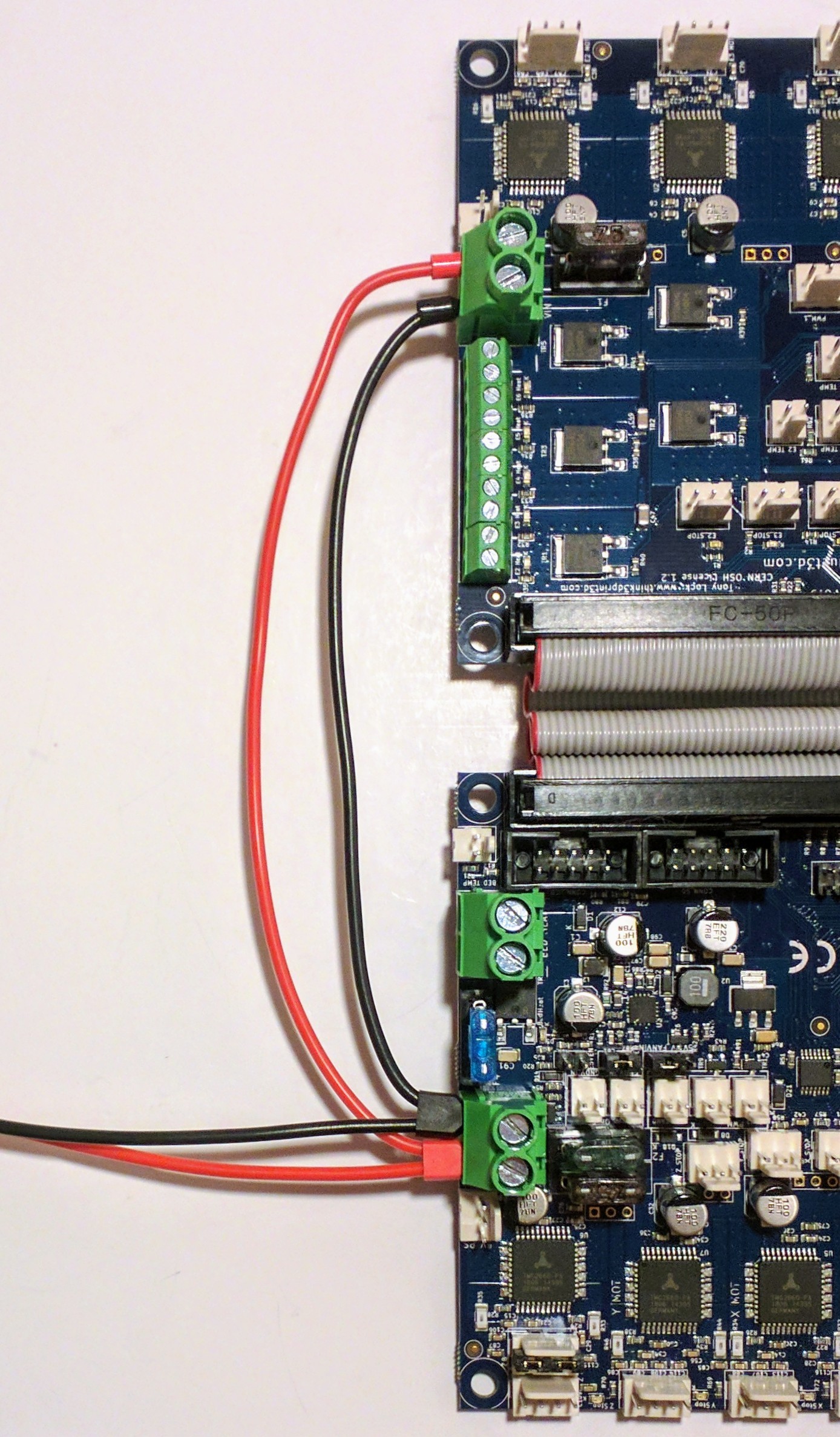
- Connect VIN and GND terminals of the DueX5 to the corresponding terminals of the Duet 2. Do not run separate ground wires from each terminal block back to the power supply unless the power supply is very close (less than 100mm) to the Duet 2 and DueX. Instead, run a very short and thick ground wire directly from the negative (-) terminal of the VIN terminal block on the DueX board to the negative VIN terminal of the Duet. Also connect the negative wire from your power supply to the negative VIN terminal of the Duet. You can run separate +VIN wires from the Duet 2 and DueX back to the positive terminal of the power supply if you wish. The screw terminal rated current is 25A maximum. At high currents, it is essential to use either ferrules or solid core wire with the terminal blocks on the Duet 2 and DueX.
- Caution! On early production (v0.6, v0.7) DueX2 and DueX5 boards, the VIN and GND markings on the underside of the board are incorrect and should be swapped over, so GND is the terminal that is also marked -, and VIN is the terminal that is also marked +.
- Important! You must have a reliable low-resistance connection between the negative (ground) terminals of the two VIN terminal blocks. Failure to do so may result in high currents flowing in the ground connectors of the ribbon cable and may cause damage to the Duet 2 or DueX. Preferably, make this connection using either solid core wire, or stranded core wire with ferrules of the correct size crimped on securely. Re-tighten the terminal block screws regularly for the first few days of use, to make sure there is no creep in the wires causing the screws to become loose.
- Important! If you have previously used the Duet (0.6 and 0.8.5) with DueX4 expansion board, note that the VIN terminal block polarity of the DueX2 or DueX5 is not the same as on the DueX4. Instead, the + and - terminals line up between the two boards when the Duet 2 and DueX5 are positioned back-to-back.
- You do not need to connect anything to the 5V_EXT_POWER connector unless you want to supply external 5V power to power servos and fans.
- As with the Duet 2, you must never connect or disconnect anything (except the USB connector) when the board is powered up. In particular, connecting or disconnecting stepper motors while powered may damage the stepper driver chips.
¶ Power jumpers
- Place the fan voltage select jumper in the 5V, 12V or VIN position according to your needs
- Place the endstop voltage selection jumper in the 5V or 3.3V position according to your needs
- Place the 5V_SELECT jumper in the INT position, unless you want to provide 5V power to servos and fans from the external 5V input
- If you will be using VIN power greater than 12V and you wish to enable the on-board 12V converter, put a jumper across the 12V_EN PINS
¶ Using multiple power supplies
In some cases, where current draw is particularly high, for example you have a large number of heaters, you may want to connect more than one PSU.
- The grounds of the VIN connectors of the Duet and DueX should be tied together by a short thick wire as usual.
- If you power up the Duet before you power up the DueX, the stepper drivers on the DueX won't get initialised. Ideally power them up at the same time, or the DueX first.
- If the VIN to the DueX goes below the minimum level (about 10V) then the stepper drivers on the DueX will stop functioning, but you won't be warned about it, because VIN to the DueX is not monitored separately.
- It should be possible to use PSUs of different voltages, eg 24V and 12V.
- Another way to use 2 PSUs would be to use one to power the bed heater only and the other to power everything else.
¶ Commissioning
The DueX2 or DueX5 is supported in firmware 1.16 and later. You must upgrade your firmware if you are using an earlier version.
- Double check your wiring, in particular the polarity and security of the connections to the VIN terminal block. The DueX is not protected against reverse supply voltage polarity.
- Apply 5V power only, for example via the USB port on the Duet 2.
- Connect to the Duet 2 via Duet Web Control, or using a USB host program such as Pronterface.
- If using DWC, go to the Gcode Console page
- Send command M115. Check that the ELECTRONICS string reports "Duet 2 WiFi + DueX5" or "Duet 2 WiFi + DueX2" as appropriate. If the "DueX5" part is missing, remove power and check your wiring.
- If you have connected additional thermistors, thermocouples or PT100 sensors, send appropriate GCode commands to enable them and test that they are giving the correct readings.
- If everything is working so far, apply 12V or 24V power and proceed with testing other devices you have connected.
¶ PCB revision history
DueX5 and DueX2 have undergone a number of minor PCB revisions, from the original release (v0.6) to the current (v0.11). All DueX revisions are compatible with all PCB revisions of the Duet 2 Wifi and Duet 2 Ethernet.
These changes were done to make it easier to change between Duex5 and DueX2 mode by replacing some of the drill/solder jumpers with normal jumpers on pin headers. Connecting external drivers to D7, D8 and D9 positions is now easier as Molex KK headers are provided.
- Replaced the drill/solder jumpers for the DueX2/5 select and driver 7,8,9 with pin header jumpers.
- Changed the test points for D7,8,9 to a Molex KK header, added an endstop pin and ground to the header as well to make it easier to connect the fault line of the external driver to this header as well.
- Modified the series resistors of the temperature inputs to be 2k2 so they perform better with PT1000 sensors. From RRF3.4 the DueX5 version will be detected and the correct R values set in M308, for RRF 3.3 and earlier use R2200 in the M308 command.
- Added a normally connected solder jumper (drill out to disconnect) to the enable line of each stepper driver. This allows for the onboard drivers to be disabled if required.
Compared to PCB revision v0.9 the following change has been implemented:
- Reduce the I2C pullup resistors from 4k7 to 1k0 to improve I2C communication reliability.
Compared to PCB revision v0.8a the following changes have been implemented:
- Further changes to the layout of the 12V circuit to further reduce EMI.
- Moved the location of the 12V enable jumper.
- Change the layout around the SX1509 to improve assembly..
- Added a Mini blade fuse holder and fuse for V_IN (supplied with a 7.5A fuse).
- Added capacitors on stepper driver outputs to reduce EMI
- Minor routing changes.
Compared to PCB revision v0.8 the following changes have been implemented:
- Changed the layout of the 12V BUCK circuit to further reduce EMI.
- Addition of a 12V output header
- Minor routing changes and modification of capacitor values
- Changed the normal component population to only omit the stepper components on DueX2.
Compared to PCB revision v0.6 the following changes have been implemented:
- Added an additional fan MOSFET (now 6 fans on the DueX).
- Added flyback diodes on the Fan outputs.
- Minor routing changes.
