¶ Introduction
RepRapFirmware allows you to compensate for the fact that the X, Y, and Z axes of your machine may not have been assembled at perfect right angles, using Gcode M556 for axis skew compensation. Ideally, your machine will be have been built perfectly square. This page tells you how to implement orthogonal axis compensation if you were not able to.
¶ Original RRF method
The first part of these instructions for calibrating M556 is based on the instructions from RepRap Ltd, who kindly allowed us to reproduce the source material here.
¶ Print the calibration parts
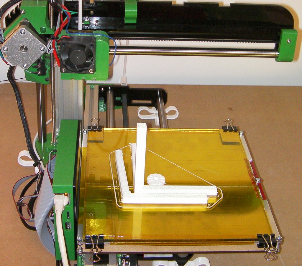
Download and print the orthogonal axis compensation test pieces, as in the picture above. STL files are available here: 60mm calibration piece or 90mm calibration piece. The original 3D model (OpenSCAD) for the test pieces are here.
Before you remove the pieces from the bed, use a felt-tipped pen to label the axes of the three-legged piece. In the picture above, X runs left-right, Y runs front-back, and Z runs down-up.
¶ Setting the compensation from the printed test parts
¶ Assemble the gauge
Clean any extraneous wisps of filament or small lumps on the surface of the printed parts away.
Parts:
- 1 x M3 screw, at least 20mm long, threaded all the way up the screw.
- 2 x M3 nuts
- 1 x M3 washers
Optionally:
- 1 x ballpoint pen spring
- 2 x M3 washers
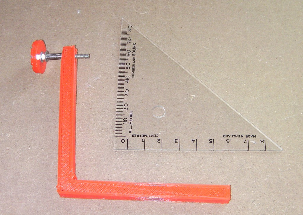
An M3x35mm hex head screw and spring is shown in the pictures for the axis compensation wheel. You don’t need a special screw; use any screw you have available. An M3x20mm cap head screw, or a crosshead screws, should be long enough. It should be threaded all the way up the screw, so you can tighten the thumbwheel in place. The spring is a ball-point pen spring, but isn’t necessary.
Use an M3 screw to draw an M3 nut into the hexagonal cavity in the angled part of the gauge. Put an M3 washer under the head of the screw. Take care as you tighten the screw that the flats on the nut are aligned with the hexagon of the cavity. You will feel the tightening force increase as the nut reaches the bottom of the cavity.
Then assemble the measuring screw. An M3 hex-headed screw fits in the cavity in the top of the thumbwheel, if you have one available. Secure it there with a nut with a washer under it on the other side of the wheel. Then, optionally, put a washer, a spring, and another washer on the screw and screw it into the nut embedded in the cavity of the angled piece as shown above.
The order goes: M3 screw, thumbwheel, washer, nut, (washer, spring, washer, if available) angled piece, nut embedded in the angled piece.
The thumbwheel in the test print has 10 radial indentations to allow you to count turns of it. The thread pitch of an M3 screw is 0.5mm, so each gradation is 0.05mm. Use a felt-tipped pen to mark one indentation so you can identify it as the wheel turns.
¶ Set the guage zero point
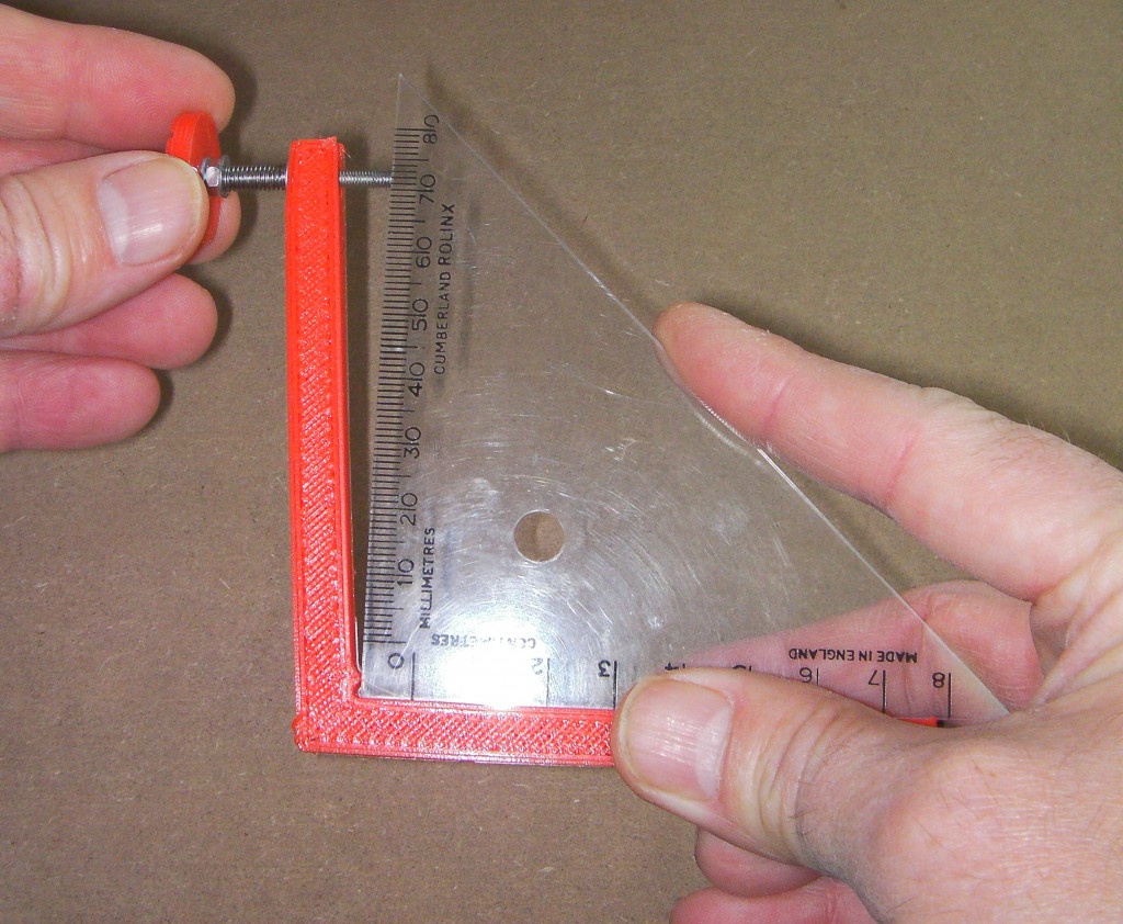
Now use a set square to set the screw at just the right position for a right-angle, as shown above. Push the set square against the small projection near the angle. But don’t force things or push too hard. You don’t want to distort the pieces.
Note the position of the mark you made on the thumbwheel.
Measure the distance between the tip of the projection near the angled corner and the centre of the end of the screw. Let’s call the distance d mm.
¶ Measure the offset
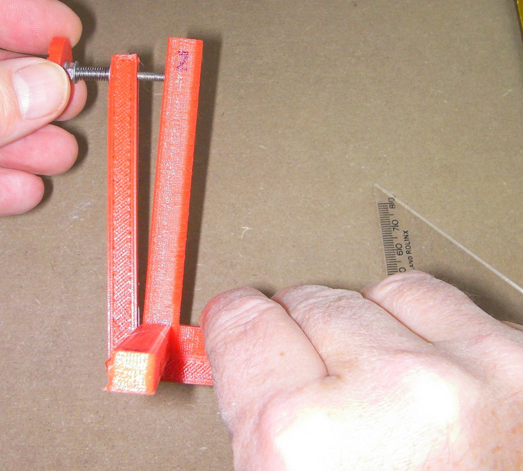
Now take the three-legged test piece that you printed. Hold it in the same place as the set square, and see how much (if at all) you have to turn the thumbwheel to just touch it. Note down the turns, and whether they were clockwise/inward/acute-angle/negative or anti-clockwise/outward/obtuse-angle/positive.
Suppose you need 1.3 clockwise turns. The pitch of an M3 thread is 0.5mm, so this means that the axis pair you have measured is -0.65mm away from a true right angle.
You can take several readings and average them – always more accurate. If you do, re-zero with the set square before each reading.
Measure all three pairs of axes: XY, YZ and XZ and write down the measurement for each.
¶ Configuring M556
The format for the M556 command is
M556 S[d] X[XY] Y[YZ] Z[XZ]
where [d] is the distance in mm you measured on the guage between the projection and the end of the screw. Suppose d = 75, and the XY, YZ and ZX measurements are XY = -0.65, YZ = 0.9, and ZX = 0.2. Then send:
M556 S75 X-0.65 Y0.9 Z0.2
You can check the skew compensation used by sending M556, e.g.:
M556
Axis compensations - XY: -0.00867, YZ: 0.01200, ZX: 0.00267
Note that the skew factor is the measured distance / d, e.g. XY / d = -0.65 / 75 = -0.00867
Your machine will now correct for the angles between the axes when it prints.
¶ Finishing up
You can put the M556 command in your config.g file. Or you can put it in a short file called, say, setaxes.g and upload that to your Duet's SD card using the web interface. Then, when you run that file, it will set your axis compensation.
To check that the axis compensation has worked, apply it, print the test pieces again, and check them with the set-square and gauge. This time you should find that all three legs of the largest test piece are at right angles to each other.
¶ Diagonal measurement method
This is a newer method to determine the skew factor. It also requires a number of printed calibration parts, but no extra parts. The following text borrows heavily from the notes in the Marlin configuration.h file.
¶ Print the calibration parts
Print a test square, e.g. this calibration square on Thingiverse. This has squares for both horizontal (XY) and vertical (YZ, ZX) axes.
You can print a cube, but make sure that the corners don't bulge if you are measuring across them, to get an accurate measurement.
¶ Measure the diagonals
For your chosen axes:
- measure the diagonal A to C
- measure the diagonal B to D
- measure the edge A to D
Use these diagrams for reference:
    Y                     Z                     Z
    ^  E--B-------C       ^  E--B-------C       ^  E--B-------C
    |  | /       /        |  | /       /        |  | /       /
    |  |/       /         |  |/       /         |  |/       /
    |  A-------D          |  A-------D          |  A-------D
    +-------------->X     +-------------->Y     +-------------->X
    XY SKEW               YZ SKEW               ZX SKEW
¶ Calculate the skew factor
Skew factors can be calculated manually:
AB = SQRT (( AC * AC + BD * BD - 2 * AD * AD ) / 2 ))
This calulates the length of the side AB of a parallelogram, from the diagonals AC and BD, and the given side length AD. AD should equal BC, and AB should equal CD.
Angle_BAD = ACOS (( AC * AC - AB * AB - AD * AD ) / ( 2 * AB * AD ))
This calculates the angle BAD in radians, using the Law of Cosines.
Skew factor = -TAN ( PI / 2 - Angle_BAD )
This subtracts angle BAD from pi/2 radians (90°) to get the angle EAB (which is the angle of the skew), then calculates the TAN of this (ie EB / AE, which is what you measure using the first method) to get the skew factor.
Note: if the angle BAD is acute (ie AC is greater than BD, as in the diagrams above) the skew factor should be negative, and if the angle is obtuse (ie AC is less than BD) the skew factor should be positive. The negative TAN sets this correctly, for RepRapFirmware.
Or you can use the following Gcode in RRF v3.x to calculate the skew factor. Copy it into a macro and upload it to your Duet. Edit the AC, BD and AD values to your measured values:
; Save to 0:/macros/Skew calculator.g
; Inputs
var AC = 302.44199
var BD = 292.11101
var AD = 200
var axis = "X" ; X = XY, Y = YZ, Z = ZX

; Compute skew
var AB = sqrt((var.AC * var.AC + var.BD * var.BD - 2 * var.AD * var.AD)/2)
var BAD = acos((var.AC * var.AC - var.AB * var.AB - var.AD * var.AD)/(2 * var.AB * var.AD))
var skew = -tan(pi/2 - var.BAD)
var AE = sin(var.BAD) * var.AB
var EB = var.skew * var.AE
var skewAtbaseHeight = var.skew * var.AD

echo "Inputs: AC = " ^ var.AC ^ "mm, BD = " ^ var.BD ^ "mm, AD = " ^ var.AD ^ "mm, axis = " ^ var.axis
echo "Calculated: Skew = " ^ var.skew ^ " or " ^ degrees(var.BAD)-90 ^ "° AB = " ^ var.AB ^ "mm, AE = " ^ var.AE ^ "mm, EB = " ^ var.EB ^ "mm, Skew @ " ^ var.AD ^ "mm = " ^ var.skewAtbaseHeight ^ "mm"
echo "Send either: M556 S1 " ^ var.axis ^ var.skew ^ " or: M556 S" ^ var.AD , var.axis ^ var.skewAtbaseHeight
Example output on running the above macro:
M98 P"0:/macros/Skew calculator.g"
Inputs: AC = 302.4420mm, BD = 292.1110mm, AD = 200mm, axis = X
Calculated: Skew = -0.0349208 or -2.0000076° AB = 220.0000mm, AE = 219.8660mm, EB = -7.6778984mm, Skew @ 200mm = -6.9841623mm
Send either: M556 S1 X-0.0349208 or: M556 S200 X-6.9841623
Note: the skew value in the above example is quite large! Most skew factors will be much smaller. A skew distance of 2mm at 200mm gives a skew factor of 2 / 200 = 0.01, or around 0.57° from square. If you get figures much higher than this, it would be better to try and get the frame mechanically squarer.
Calculate values for all axes (XY, XZ and/or YZ) that require them.
¶ Configuring M556
You can configure M556 either directly with the calculated Skew factor or with Skew distance and AD length. Axes can be set individually, or all at once.
Suppose the AD and XY measurements are AD = 200 and XY = -64.03204. Then send:
M556 S200 X-64.03204 ; set XY Skew distance @ 200mm: -64.03204mm
; or send:
M556 S1 X-0.3201567
For multiple axes, you may send something like:
M556 S200 X-64.03204 Y-3.1 Z2.25
; or send:
M556 S1 X-0.32016 Y-0.01550 Z0.01125
You can check the skew compensation used by sending M556, e.g.:
M556
Axis compensations - XY: -0.32016, YZ: -0.01550, ZX: 0.01125
Your machine will now correct for the angles between the axes when it prints.
¶ Finishing up
Usually the best place for the M556 command in your config.g file. You can put it in a macro file called, say, setaxes.g and upload that to your Duet's SD card using the web interface. Then, when you run that file, it will set your axis compensation.
To check that the axis compensation has worked, apply it, print the test pieces again, and check the diagonal measurements again. This time you should find the diagonals are equal.