¶ Scope
This document is relevant to: all Duet boards
Firmware versions: all firmware versions
¶ Introduction
The Duet series supports four types of temperature sensor: thermistor, PT1000, thermocouple, and PT100. This page describes the support for PT100 and other RTD (Resistance Temperature Detector) temperature sensors in RepRapFirmware for Duet electronics.
¶ Hardware
¶ PT100 temperature sensor daughterboard
To connect a PT100 sensor to a Duet, you need an RTD interface board based on the MAX31865 chip. Duet3D produce a two-channel PT100 temperature sensor daughterboard for Duet 3 and Duet 2 mainboards.
¶ Supported hardware
Each daughterboard supports 2 channels, ie two temperature sensors per daughterboard. Duet mainboards and expansion boards support none, one or two daughterboards. Refer to the table below.
| Duet board | Number of boards supported | Pin names (RRF 3) | Channel (RRF 2) |
|---|---|---|---|
| Duet 3 Mainboard 6HC | 2, stacked | spi.cs0 to spi.cs3 | - |
| Duet 3 Mainboard 6XD | 2, stacked | spi.cs1 to spi.cs4 | - |
| Duet 3 Mini 5+ | 1 | spi.cs1 to spi.cs2 | - |
| Duet 3 Expansion 3HC | 2, stacked | spi.cs0 to spi.cs3 | - |
| Duet 3 Toolboard 1LC | 0 | - | - |
| Duet 3 Expansion 1XD | 0 | - | - |
| Duet 2 WiFi / Ethernet | 2, stacked | spi.cs1 to spi.cs4 | 200 to 203 |
| DueX2 / DueX5 | 2, stacked | spi.cs5 to spi.cs8 | 204 to 207 |
| Duet 2 Maestro | 1 | spi.cs1 to spi.cs2 | 200 to 201 |
Boards that support only one daughterboard can have either a Thermocouple or PT100 daughterboard connected, but not both.
¶ PCB revisions
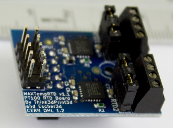
There have been a couple of different versions of the PT100 temperature sensor daughterboard. The main difference is the configuration of the jumpers to select between 2-wire and 4-wire PT100 sensors. See the wiring section below for the function of these jumpers.
This image shows version 1.1, which has jumpers to select between 2 wire and 4 wire PT100 sensors.

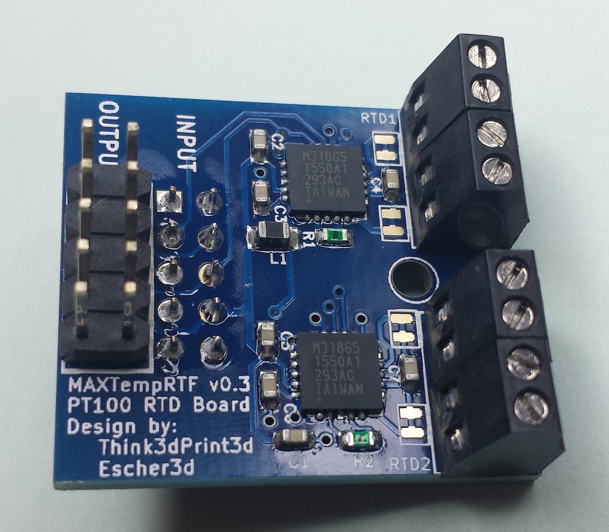
Older board versions (pre v1.1) have solder pads to select between 2 wire and 4 wire PT100 sensors:

¶ Description of input/output pins
Each channel of the PT100 daughterboard has a 4-position terminal block. We'll number the terminals 1, 2, 3 and 4 in order (it doesn't matter which end you start from, because PT100 sensors don't care about polarity). Terminals 1 and 4 supply current to the sensor, and the voltage developed across the sensor is measured between the terminals 2 and 3.
¶ Installation of PT100 daughterboard
¶ Mounting on the Duet mainboard
The temperature daughterboard connects to the TEMP_DB connector on the mainboard. Make sure the temperature daughterboard is orientated correctly before connecting, see the wiring diagram for your mainboard.
We supply a plastic pillar with each daughterboard, to secure the daughterboard to the Duet or to the daughterboard below it. If the prongs of the pillar won't go into the hole in the circuit board easily, gently squeeze the prongs together with a pair of pliers first.
¶ Mounting multiple daughterboards
On mainboards that support more than one temperature daughterboard, the second daughterboard is connected by stacking it on top of the first. You can have two daughterboards of the same type (PT100 or Thermocouple), or have one of each.

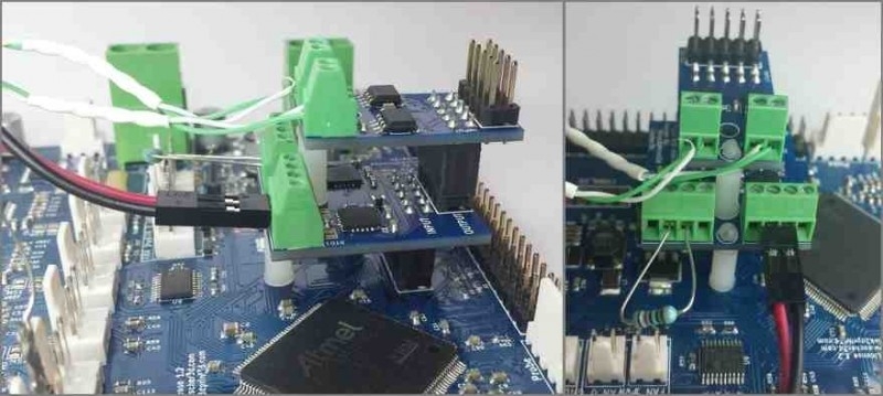
This image shows a thermocouple daughterboard stacked on top of a PT100 board. The right-hand connector of the PT100 board has a 2-wire PT100 sensor connected to it. The left hand connector has a test resistor connected to it (see later).
¶ Connecting more temperature sensor daugtherboards
- On Duet 3, some CAN expansion boards support additional temperature sensor daughterboards, and multiple expansion boards can be chained together.
- On Duet 2 Wifi and Ethernet, two additional temperature sensing daughterboards can be stacked on a connected DueX5 & DueX2 expansion board, providing an additional 4 temperature sensing channels.
¶ Wiring the PT100 temperature sensor
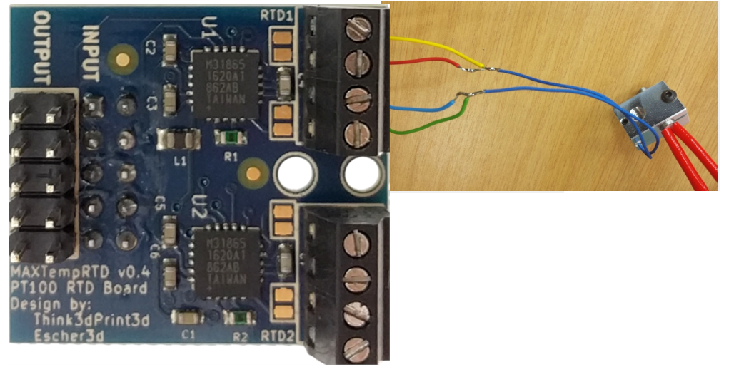
On the first temperature daughterboard (ie closest to the mainboard), the terminal blocks labelled RTD1 and RTD2 will be the first and second temperature measurement channels respectively. If you stack two PT100 daughterboards, the terminal blocks labelled RTD1 and RTD2 on the upper board will be the third and fourth temperature measurement channels.
PT100 temperature sensors can be wired in either a 2-wire or 4-wire configuration. 3-wire PT100 sensors are also available, but these will need to be wired as a 2-wire, or an extra wire added to be wired in 4-wire.
2-wire connections have the advantage of wiring simplicity. 4-wire connections have the advantage of greater accuracy; the extra wires compensate for the resistance drop in the wires, making readings more accurate. 4-wire does not improve resistance to interference; better approaches to reduce noise include twisted wiring, isolation from noise sources, shielded wiring, better grounding of components etc.
- Connect the PT100 wires to terminals 2 and 3
- Configure the channel for 2-wire operation:
- Recent production PT100 daughterboards (v1.1 or later see the image above) have 2 sets of 2 jumper pins per channel. Install jumpers on those pins, ie between pin 1 and 2 and between pin 3 and 4.
- On an older production PT100 daughterboard, either bridge each pair of solder pads next to the terminal block, or add a wire between terminals 1 and 2, and another between terminals 3 and 4.
- On a pre-production PT100 board there is already a trace bridging each pair of solder pads.
- Connect the two wires that go to one end of the PT100 resistance element to terminals 1 and 2 (it doesn't normally matter which wire in each pair goes to which terminal)
- Connect the two wires that go to the other end of the PT100 resistance element to terminals 3 and 4
- Configure the channel for 4-wire operation:
- Recent production PT100 daughterboards have 2 sets of 2 jumper pins per channel. Remove the jumpers from those pins.
- On an older production PT100 daughterboard, ensure that the 2 pairs of solder pads next to each terminal block are not bridged.
- On a pre-production daughterboard, cut the fine traces that bridge each pair of solder pads next to the terminal block.

See dc42's blog post here for additional information about using a 4-wire PT100 connection.
¶ Firmware configuration
In RepRapFirmware 3 you first create a sensor using M308 then assign it to a heater using M950.
For example:
;Duet 3 6XD, Mini 5+
M308 S3 P"spi.cs1" Y"rtd-max31865" ; define temperature sensor number 3 as a PT100 on the first port of a temperature daughterboard plugged into the mainboard.

;Duet 3 6HC
M308 S3 P"spi.cs0" Y"rtd-max31865" ; define temperature sensor number 3 as a PT100 on the first port of a temperature daughterboard plugged into the mainboard.

;Duet 3 3HC
M308 S3 P"3.spi.cs0" Y"rtd-max31865" ; define temperature sensor number 3 as a PT100 on the first port of a temperature daughterboard plugged into the expansion board with CAN bus address 3.

;Duet 2
M308 S1 P"spi.cs1" Y"rtd-max31865" ; create sensor number 1 as a PT100 sensor in the first position on the Duet 2 daughterboard connector
To tell the firmware to use a RTD channel for one of the heaters, use the X parameter in the M305 command for that heater to specify the required channel (200 to 203 on the Duet 2 WiFi/Ethernet, 204 to 207 on the DueX5 or DueX2).
For example:
M305 P1 X200
This tells the firmware that for heater 1 (which is normally the first hot end heater) it should sense the temperature using the PT100 board whose CS pin is connected to NPCS0. The S, T, B, H and L parameters of the M305 command are not used. In firmware 1.20 and later, you can optionally use the R parameter to specify the value of the reference resistor if it is not 400 ohms.
¶ Troubleshooting
- Check board functionality: the daughterboard comes with a 100Ω resistor that you can wire in place of a two wire sensor to check the board is working correctly. With the resistor in place, the reading should be 0°C.
- Connect the 100 ohm test resistor (supplied with the daughterboard) to terminals 2 and 3
- Fit the 2 jumpers as for a 2-wire PT100 sensor
- RepRapFirmware should report a temperature very close to 0 degC for that channel.
- If the reading at room temperature is higher than it should be, then you probably have a bad connection between the RTD interface board and the sensor, or the wires to the sensor are too long or too thin. Each additional ohm of wiring resistance will increase the temperature reading by 2.5C. Using a 4 wire solution PT100 sensor will improve this. If you only have a 2 wire P100 sensor you can still improve the accuracy by using 4 wires for the majority of the distance as described in dc42's blog post here.
- If the sensor readings are subject to interference, some approaches to reduce noise include twisted wiring, isolation from noise sources, shielded wiring, better grounding of components. Canbus 2-wire cable has been recommended in the past, as it is double shielded with a ground core to attach to a ground pin. Check other connections, eg plugs, in the wiring for loose joints, too.