¶ Introduction
The Duet range of machine controllers support one or more SPI daughterboards which provide expanded sensor connectivity. These daughterboards connect to the Duet digitally over SPI.
¶ Features
¶ Supported hardware
Each daughterboard supports 2 channels, ie two PT100 sensors per daughterboard. Duet mainboards and expansion boards support none, one or two daughterboards. Refer to the table below.
| Duet board | Number of boards supported | |
|---|---|---|
| Duet 3 Mainboard 6HC | 2, stacked | |
| Duet 3 Mainboard 6XD | 2, stacked | |
| Duet 3 Mini 5+ | 1* | |
| Duet 3 Expansion 3HC | 2, stacked | |
| Duet 3 Expansion 1HCL | 1, v2.0 only | |
| Duet 3 Roto Toolboard | Not supported | |
| Duet 3 Toolboard 1LC | 0 | |
| Duet 3 Expansion 1XD | 0 | |
| Duet 2 WiFi / Ethernet | 2, stacked | |
| DueX2 / DueX5 | 2, stacked | |
*Note,the Mini 5+ Ethernet v1.03 supports two SPI DB boards stacked, v1.02a and earlier support 1
Mainboards and expansion boards that support only one daughterboard can have either an ADC, Thermocouple or PT100 temperature sensor daughterboard connected, but not two. Those that support two SPI daughterboards can have different daughterboards connected.
¶ PT100 sensor support
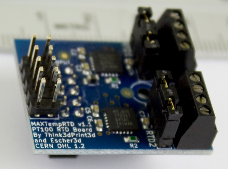
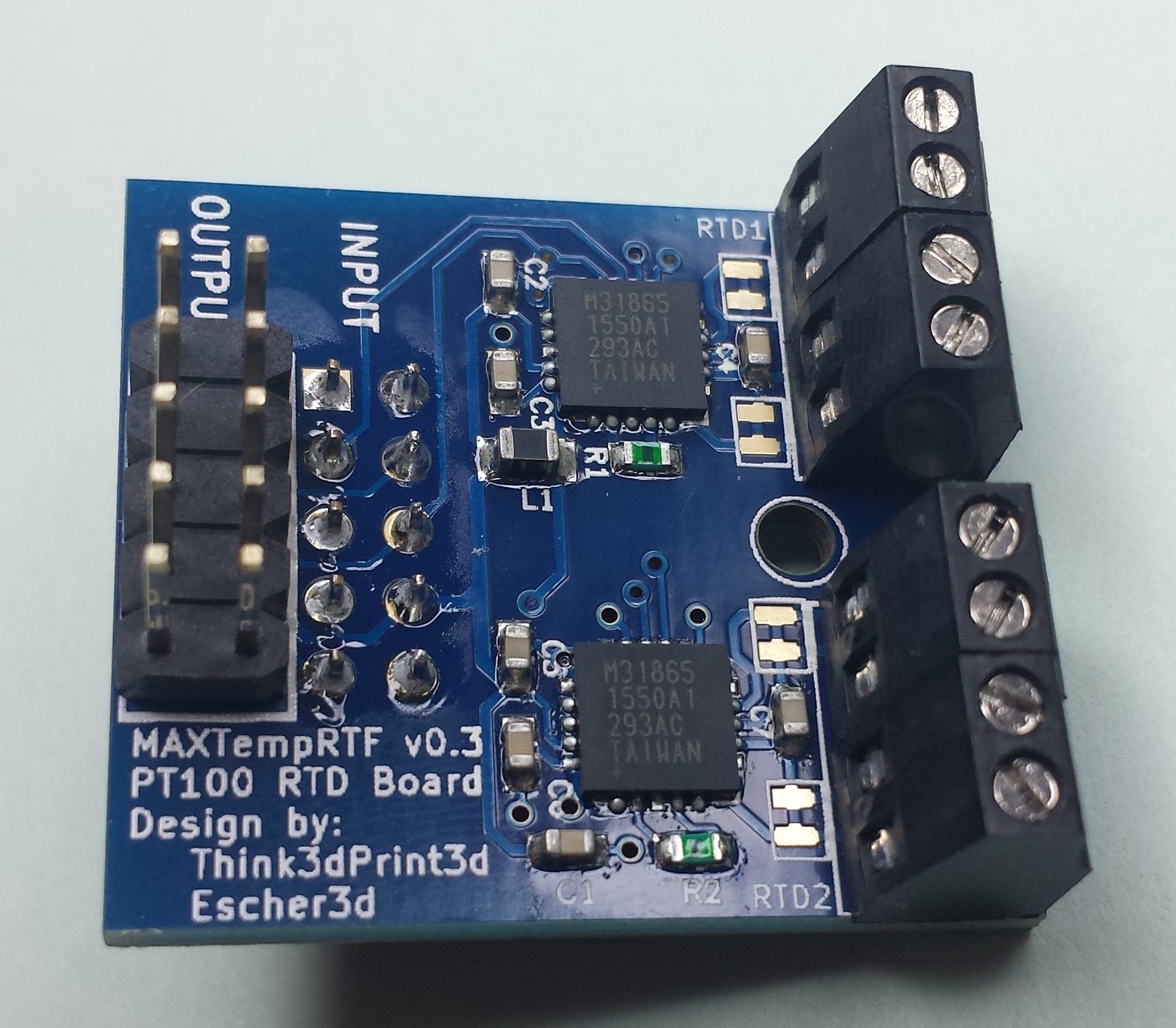
The PT100 daughterboard uses the Maxim Integrated MAX31865 RTD sensor IC. This IC supports 2,3 or 4 wire PT100 connections. The mode can be set using jumpers on the board. With the jumpers on/bridged the board expects a 2 wire PT100 sensor. With the jumpers off/cut a 4 wire PT100 sensor can be used. The change between older versions and 1.1 was to move from solder jumpers to pin jumpers.
¶ MAX31865 sensor IC details
An external resistor sets the sensitivity for the RTD being used (in the case of the Duet3D daughterboard this is a PT100) and a precision delta-sigma ADC converts the ratio of the RTD resistance to the reference resistance into digital form. High Accuracy: 15-Bit ADC Resolution; Nominal Temperature Resolution 0.03125°C (Varies Due to RTD Nonlinearity). Total Accuracy Over All Operating Conditions: 0.5°C (0.05% of Full Scale) max. For more information see the Maxim Integrated MAX31865 product page.
¶ Operating limits
- Maximum ambient temperature: 70°C
¶ Open source
- Hardware source files are available on Github.
- Duet hardware is built with Open tools: designed in KiCad. Using open tools means the barrier to getting involved is as low as possible.
¶ 3D model
The STEP file for the Duet3D PT100 temperature sensor daughterboard is shared on the Duet3D github here.
¶ Installation and configuration
For setting up the Duet us use PT100 sensors see Connecting PT100 temperature sensors
¶ Other Temperature sensors
The Duet range of machine controllers support various other temperature sensors. See:
¶ Revision history
The following minor changes from v1.1 to 1.1a:
- The addition of a ground point between the two sets of screw terminals to make it easier to ground shielded wires.
- Added 0u1 filtering capacitors on RTDIN(+/-).
- Switched from 1x400R to 2x200R in series reference resistors for component availability reasons.
From version 1.1 onwards there are two pin jumpers per input channel.

Versions of the board before v1.1 had solder jumpers to convert from 2 wire to 4 wire.
