¶ Scope
This document is relevant to: all Duet boards
Firmware versions: all firmware versions
¶ Introduction
The Duet series supports 4 types of temperature sensor: thermistor, PT1000, thermocouple, and PT100. This page describes the support for thermocouple temperature sensors in RepRapFirmware on Duet electronics.
¶ Hardware
¶ Thermocouple daughterboard
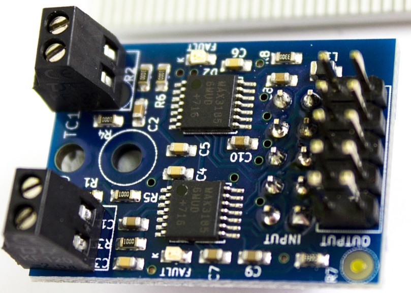
To connect a thermocouple to a Duet, you need thermocouple interface board based on the MAX31855 or the newer MAX31856 chip. Duet3D produce a two-channel thermocouple daughterboard for Duet 3 and Duet 2 mainboards.
¶ Supported hardware
Each daughterboard supports 2 channels, ie two thermocouples per daughterboard. Duet mainboards and expansion boards support none, one or two daughterboards. Refer to the table below.
| Duet board | Number of boards supported | Pin names (RRF 3) | MAX31856 Channel (RRF 2) | MAX31855 Channel (RRF 2) |
|---|---|---|---|---|
| Duet 3 Mainboard 6HC | 2, stacked | spi.cs0 to spi.cs3 | - | |
| Duet 3 Mainboard 6XD | 2, stacked | spi.cs1 to spi.cs4 | - | |
| Duet 3 Mini 5+ | 1 | spi.cs1 to spi.cs2 | - | - |
| Duet 3 Expansion 3HC | 2, stacked | spi.cs0 to spi.cs3 | - | - |
| Duet 3 Toolboard 1LC | 0 | - | - | - |
| Duet 3 Expansion 1XD | 0 | - | - | - |
| Duet 2 WiFi / Ethernet | 2, stacked | spi.cs1 to spi.cs4 | 150 to 153 | 100 to 103 |
| DueX2 / DueX5 | 2, stacked | spi.cs5 to spi.cs8 | 154 to 157 | 104 to 107 |
| Duet 2 Maestro | 1 | spi.cs1 to spi.cs2 | 150 to 151 | 100 to 101 |
Boards that support only one daughterboard can have either a Thermocouple or PT100 temperature sensor daughterboard connected, but not both.
¶ Thermocouple support
There have been two versions of the thermocouple board.
| Board revision | Sensor IC | Screw terminal labels | Supported thermocouples |
|---|---|---|---|
| v1.1 | MAX31856 | TC0 and TC1 | 2 x thermocouples of type B, E, J, K, N, R, S or T |
| older versions | MAX31855 | 1 and 2 | 2 x thermocouples of type K |
¶ Installation of thermocouple daughterboard
¶ Mounting on the Duet mainboard
The temperature daughterboard connects to the TEMP_DB connector on the mainboard or expansion board. Make sure the temperature daughterboard is orientated correctly before connecting, see the wiring diagram for your board.
We supply a plastic pillar with each daughterboard, to secure the daughterboard to the Duet or to the daughterboard below it. If the prongs of the pillar won't go into the hole in the circuit board easily, gently squeeze the prongs together with a pair of pliers first.
¶ Mounting multiple daughterboards
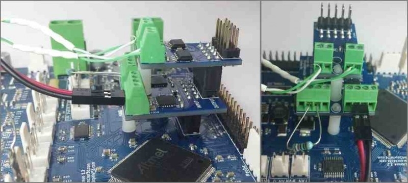
On Duet boards that support more than one temperature daughterboard, the second daughterboard is connected by stacking it on top of the first. You can have two daughterboards of the same type (PT100 or Thermocouple), or have one of each.

This image shows a thermocouple daughterboard stacked on top of a PT100 board. The right-hand connector of the PT100 board has a 2-wire PT100 sensor connected to it. The left hand connector has a test resistor connected to it (see later).
¶ Connecting more temperature sensor daughterboards
- On Duet 3, some CAN expansion boards support additional temperature sensor daughterboards, and multiple expansion boards can be chained together.
- On Duet 2 Wifi and Ethernet, two additional temperature sensing daughterboards can be stacked on a connected DueX5 & DueX2 expansion board, providing an additional 4 temperature sensing channels.
¶ Wiring the Thermocouple
- K-type thermocouples are normally chosen.
- The thermocouple must be electrically isolated from the hot end heater block.
- If the thermocouple has a bare junction, you will need to insulate it, for example with high-temperature sleeving.
- You can buy cartridge-style insulated thermocouples from E3D and elsewhere.
- The thermocouple leads should be long enough to reach your printer electronics, so that the cold junction will be at the thermocouple interface board.

Connect the thermocouple leads to one of the two terminal blocks on the daughter board. If you are using a K-type thermocouple with white and green wires, the white wire goes into the left hand terminal, looking from the wire into the terminal block.
If your daughterboard has two LEDs labelled FAULT then it uses MAX31856 chips (board revision v1.1). Terminal blocks labelled TC0 and TC1 on the lower daughter board will be the first and second temperature measurement channels respectively. If you stack two daughter boards, the terminal blocks labelled TC0 and TC1 on the upper board will be the third and fourth channels.
If your daughterboard uses MAX31855 chips (board revision earlier than v1.1) then the terminal blocks labelled 1 and 2 on the lower daughter board will be the first and second temperature measurement channels respectively. If you stack two daughter boards, the terminal blocks labelled 1 and 2 on the upper board will be the third and fourth channels.
¶ Firmware configuration
In RepRapFirmware 3 you first create a sensor using M308 then assign it to a heater using M950
For example:
;Duet 2
M308 S1 P"spi.cs1" Y"thermocouple-max31856"  ; create sensor number 1 as a thermocouple, defaulting to type K in the first position on the Duet 2 daughter board connector

;Duet 3 6XD, Mini 5+
M308 S3 P"spi.cs1"Y"thermocouple-max31856" K"J"; define temperature sensor number 3 as a J Type thermocouple on the first port of a temperature daughter board plugged into the main board.

;Duet 3 6HC
M308 S3 P"spi.cs0"Y"thermocouple-max31856" K"J"; define temperature sensor number 3 as a J Type thermocouple on the first port of a temperature daughter board plugged into the main board.

;Duet 3 3HC
M308 S3 P"3.spi.cs0"Y"thermocouple-max31856" K"J"; define temperature sensor number 3 as a J Type thermocouple on the first port of a temperature daughter board plugged into the expansion board with CAN bus address 3.
To tell the firmware to use a thermocouple channel for one of the heaters, use the X parameter in the M305 command for that heater to specify the required channel (100 to 103 for MAX31855-based interface boards, or 150-153 for MAX31856-based interface boards). For example:
M305 P1 X100
This tells the firmware that for heater 1 (which is normally the first hot end heater) it should sense the temperature using the thermocouple board whose CS pin is connected to NPCS0. The B H L and R parameters of the M305 command are not required when using thermocouples. When using MAX31856-based interface boards, the T parameter is used to specify the thermocouple type, for example:
M305 P1 X150 T"J"
If the T parameter is not present then type K is assumed.
¶ Troubleshooting
- If you have difficulty getting correct readings from the thermocouple board, try connecting a wire link between the two terminals of the terminal block instead of a thermocouple. This should produce a room temperature reading.
- If the temperature readout decreases when you heat the hotend instead of increasing, swap over the thermocouple wires in the terminal block.
- If you get wildly inaccurate or fluctuating readings, check that the thermocouple wires are securely connected in the terminal block. If you purchased a third-party thermocouple interface board, check that there is a 10nF or greater capacitor in parallel with the thermocouple terminals.
- Check that there is no connection between the thermocouple wires and the metal case of the thermocouple - this will give poor readings and could provide a short from the heater cartridge voltage to the Duet if the heater cartridge develops a fault.
- Themocouples only output about 40 microvolts per degC, so the wiring between the thermocouple and the daughter board picks up interference easily, especially by induction. Use twisted pair wiring all the way back to daughter board, and keep it away from other wiring as far as possible. If you are using a bare tip thermocouple, make sure that the thermocouple tip is insulated from the printer metalwork. If you are using a cartridge thermocouple, grounding the cartridge housing may help.
Here is a report from a user who was getting temperature spikes in the thermocouple reading:
I was able to fix that problem by taking a piece of RG-59 coax (same stuff used for cable tv) and removing the inside conductor and white insulation but leaving the wire shield in there. I helps to warm the cable up in the oven at a low temperature before pulling the the center conductor out, it helps to have two people, you have to work it out a little at a time. Then I ran the thermocouple wires through the cable, there should be plenty of room, on my dual head I ran two thermocouples through it. Then on the Duet side solder a short wire (the shorter the better) onto the shield wires in the RG-59 coax, put some heat shrink over the connection, then connect the other end of the short wire to a ground on the Duet board, any ground should work. Problem solved."
Another way to solve interference problems when using early thermocouple daughter board or third-party boards is to add a 10nF ceramic capacitor between each input pin and ground. See this forum thread for details. Current production thermocouple daughter boards have these capacitors installed already.