¶ Introduction
Duet 3 uses a CAN-FD bus to connect expansion and toolboards to the Duet 3 mainboard (currently Duet 3 Mainboard 6HC, Duet 3 Mainboard 6XD and Duet 3 Mini 5+). You can also use a Duet 3 mainboard as an expansion board; see 'Mainboard as expansion board' section below.
We chose CAN-FD because it is highly tolerant of noise (in particular, the ground noise generated by stepper motors), well-supported by modern microcontrollers, and the FD variant has enough bandwidth to support the high movement command rates needed in 3D printing and some other motion control applications.
To connect a mainboard and expansion board, both boards need power, and a CAN cable connecting the boards.
¶ Power wiring
All connected CAN boards must share a common ground connection. If you are using more than one power supply, you must connect the negative terminals of the power supplies together, or boards on different PSUs will not be able to communicate over CAN.
If all boards are powered from the same power supply, they will automatically be sharing a common ground. However, if you use (for example) one power supply for the main board and a different power supply for an expansion board, you must connect the negative output terminals of the two power supplies together.
A power supply needs to be able to provide enough current for all the boards connected to it; see Choosing the power supply for guidance. If you have a lot of boards, you may need to have more than one power supply. You may also want to run boards on power supplies that supply different voltages, eg some on 24V and some on 48V (for high voltage stepper drivers, for example). This is supported, so long as the PSUs are wired to share a common ground.
If you use a relay to control VIN power to the board, ie the power supply is already switched on, and a relay is used to turn on power to the board, you should use an inrush current limiter wired in series with VIN. See the section on Inrush current here.
OUT ports on the mainboard should NOT be used to switch power to expansion or tool boards directly. See the note at the end of the 'inrush current' section at the link above.
¶ CAN wiring
¶ Overview
CAN-FD (and CAN) is nominally a linear bus system, using a twisted pair of wires that carry a differential signal, i.e. one wire carries a high signal (CAN_H) and the other the low signal (CAN_L). This makes it very resilient to interference and electrical noise; it was developed for the automotive industry. The pair of wires need not be twisted over short distances, and can be twisted and if necessary shielded over long distances and/or for particularly noisy environments.
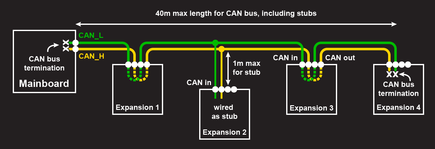
Apart from the devices at each end of the CAN bus, each device on the CAN bus needs CAN wires from the previous device, and CAN wires to the next device. The devices at each end of the bus need to 'terminate' the bus with 120 ohm resistors to avoid reflections.
Within the pair of wires, the CAN_H and CAN_L wires should remain wired separately, so the CAN_H wire always connects to the CAN_H input and output on the device, and the CAN_L wire always connects to the CAN_L input and output.
Each board on the bus must be able to read the transmissions of every other board accurately. Typically the main board is placed at one end of the bus. However, the main board does not need to be at an end of the bus if the termination resistor on the board is disabled. In some machines, the total length of CAN cabling might be lower if the main board is not at one end of the bus.
You can also have devices attached to the CAN bus by short 'stubs'. These devices are not terminated. See 'Stubs' section below for more details.
There is a limit to the maximum length of the CAN bus. By "length" we mean the total length of cable that the signal must travel over when the two nodes that are most distant from each other communicate (where "most distant from each other" means the nodes connected to each other by the longest amount of cabling). Normally, this will be the total length of cable between the two nodes at either end of the bus that have the termination resistors, ignoring any stubs. It could be longer if you have a stub that is connected close to one end of the bus, and the length of the stub is longer than the distance between the point where the stub joins the bus and the end of the bus.
The CAN bus length can be up to about 40m when using the default bit rate of 1Mbit/sec. Lower bit rates allow correspondingly longer cables, e.g. 500kbit/sec allows up to about 80m.
¶ Cables
Unshielded twisted pair cable is normally used, ideally 2 X 24AWG or thicker with an impedence of 120ohms. However, over the short cable lengths typical of desktop 3D printers and CNC machines, the cable type is not critical. On very large printers, twisted pair cable must be used.
The larger Duet 3 boards provide 6-way modular connectors for the CAN bus. These are similar to standard Ethernet connectors but have 6 ways instead of 8. You can use RJ11 and/or RJ12 cables and connectors. RJ11 is 6P2C (6 positions, 2 contacts), RJ12 is 6P6C (6 positions, 6 contacts). Some wires are also supplied 6P4C (6 positions, 4 contacts). In all cases, only the middle pair are used in a Duet CAN systems.
Twisted pair cables terminated in RJ11/RJ12 connectors are sold in some countries as "High Speed ADSL cables". One supplier of such cables is Kenable. Note, ADSL and telephone cables made with flat wire often cross the connections, making them unsuitable for CAN. See the images below.
¶ Example of a good cable:
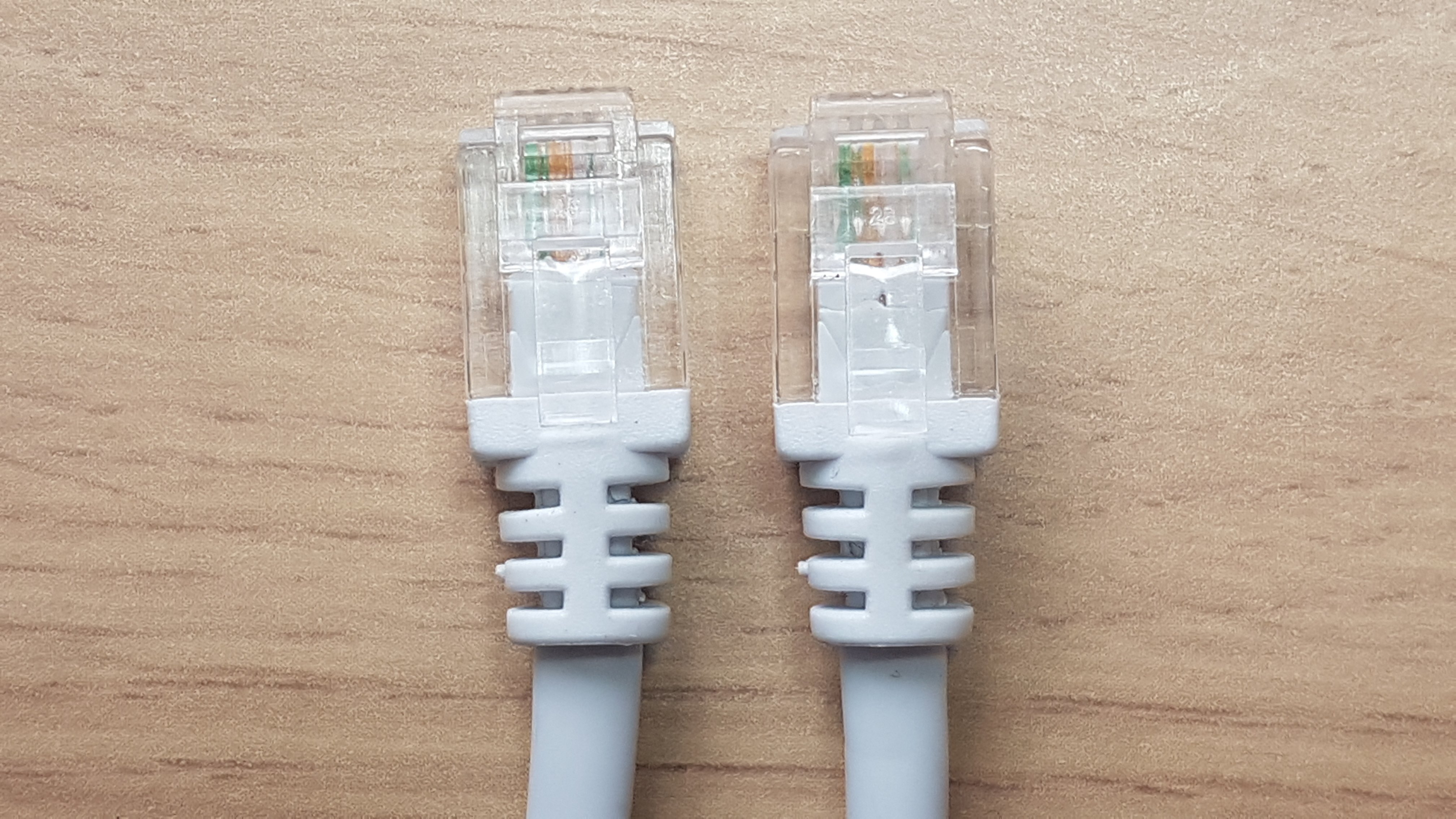 The colours of the wires going to the pins on the right is hard to see because they are white with a stripe, as is usual for twisted pairs; but the order of colours is the same at both ends.
¶ Example of an unsuitable cable:
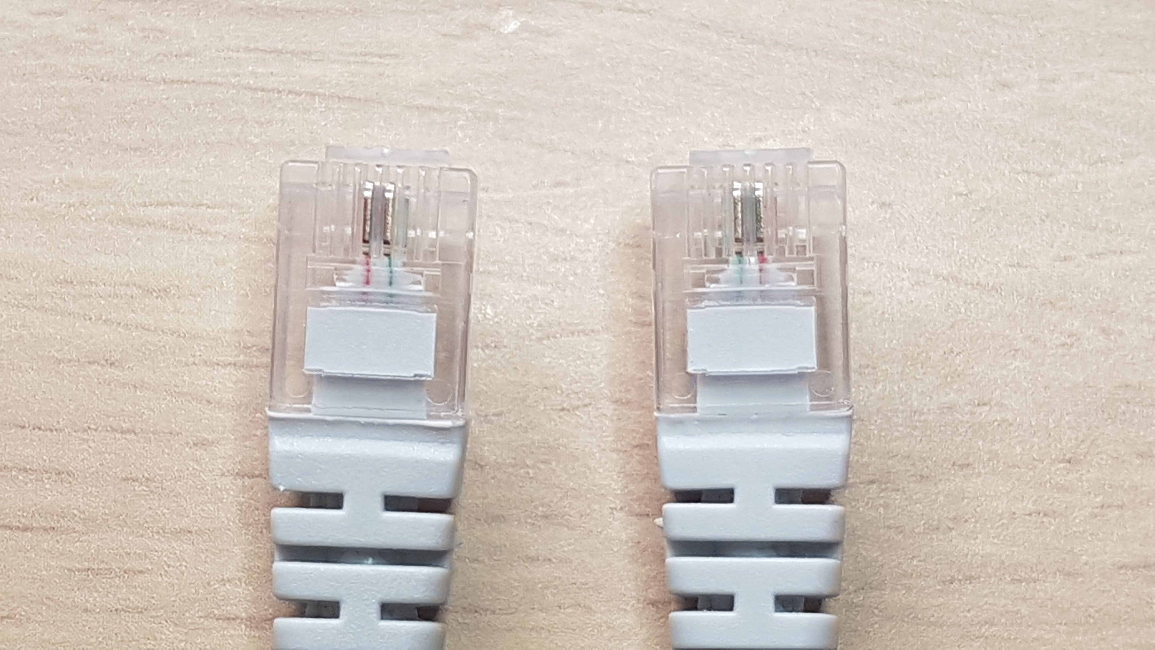 Having just the middle 2 pins wired is OK, but they are crossed so this cable is no good for CAN (it's a cable that was supplied with an ADSL or DSL modem). This is common for cables made from non-twisted-pair cable that is either flat with a seam on one side, or half-round.
¶ Make your own cables
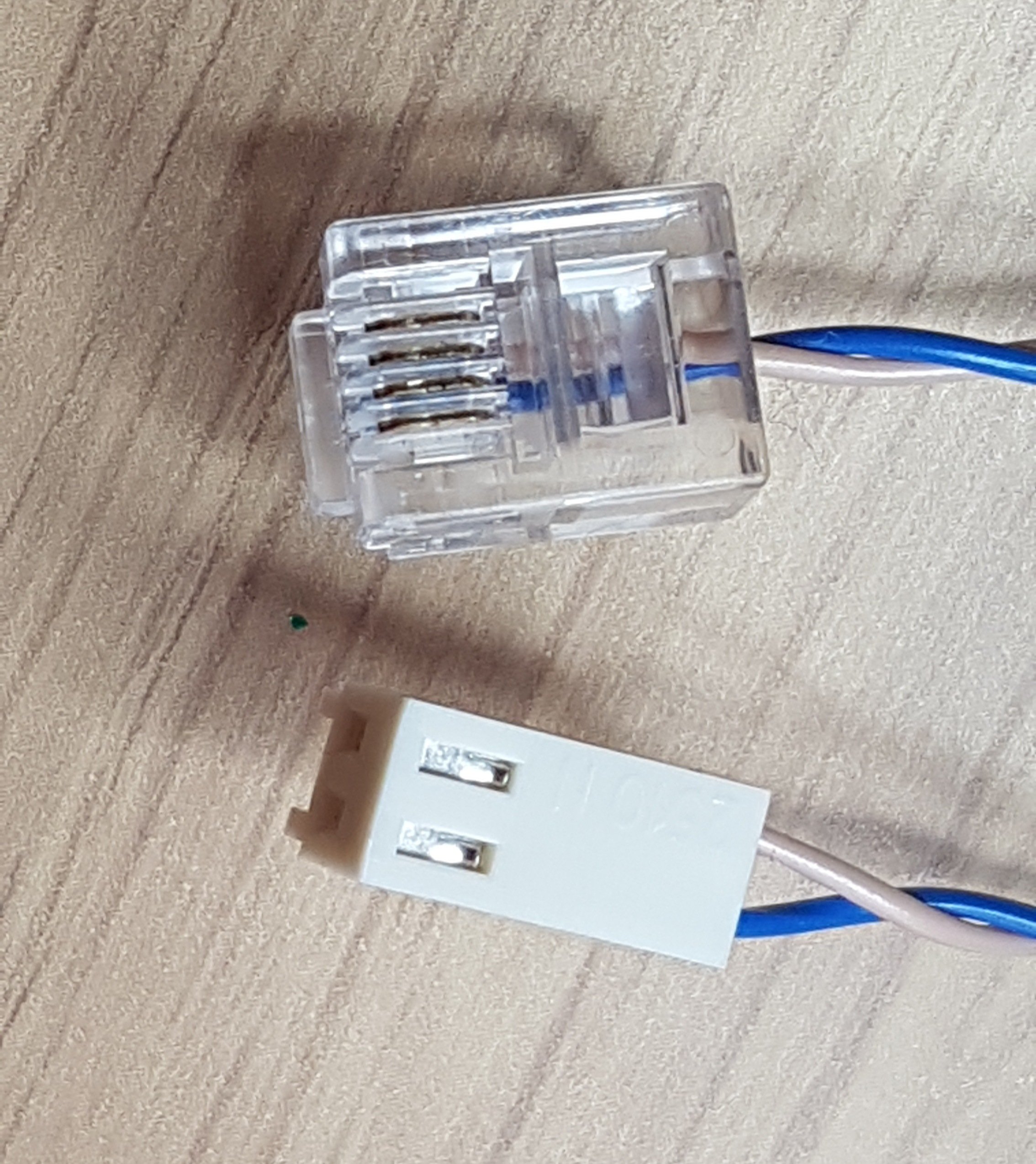 You can also make up your own cables. Kits of RJ11 (usually 6P4C) connectors and the corresponding assembly tool are readily available. For the cable, you can buy unshielded twisted pair cable (e.g. Lapp 0035101 has two twisted pairs, so suitable for connecting a Tool Board to a Tool Distribution Board); or buy a length of twisted pair ribbon cable and separate it into individual pairs; or for short distances, use telephone cable.
Note that when crimping RJ11 connectors, it is possible to over-crimp them, causing the contacts on the connector to be pressed down so far that they don't make contact with the inside the socket. Check this if you have communication problems.
This image shows a cable made to connect a Duet 3 Mini to a Tool Distribution Board.
¶ Wiring scheme
The polarity of the connections between boards matters. In all cases, connect CAN_H on one board to CAN_H on the next board, and similarly connect CAN_L to CAN_L.
¶ Daisy chain
Typically, the CAN bus is wired in a daisy-chain-style between boards. At one end will be the mainboard, with the CAN bus connecting to each subseqent board.
Daisy-chaining can be mixed with stubs to create the CAN bus that best suits your requirements.
¶ Stubs
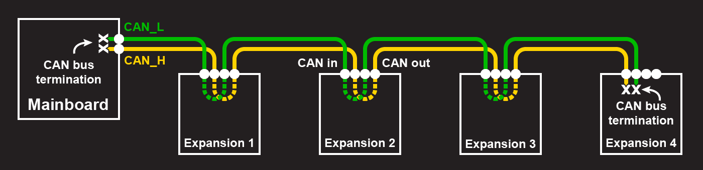
Stubs are branches off the CAN bus that are a single twisted pair of wires. The maximum recommended stub length for the 1Mbit/sec signalling rates used by Duet is 1m, and should preferably use ferrite beads to suppress ringing. Stubs can have multiple boards on them, but the total length of the stub should still not be more than 1m. The total length of all stubs should not be more than 5m.

In the above diagram, Expansion 2 and Expansion 3 are on a single stub. It may be convenient to terminate the CAN bus on Expansion 3, and remove the termination on Expansion 4, if the wire lengths require it. Then Expansion 4 is on a stub.
The CAN bus on Duet 3 boards normally runs at 1Mbit/sec by default. If the bit rate is increased using M952, signal reflections caused by stubs will be more significant, making it more important to keep stubs short and/or use ferrite beads.
Stubs can be mixed with daisy-chaining to create the CAN bus that best suits your requirements.
¶ Termination
The CAN-FD bus is a two-wire bus with 120 ohm nominal impedance. The bus needs to be terminated by 120 ohm resistors at each end, and there should be no terminators on other boards. Most boards supplied by Duet3D have CAN bus termination built-in. Mainboards have it enabled by default though it can usually be removed by drilling out the surface layer of a PCB via. On expansion and tool boards termination is usually selectable, either with a jumper or a soldered connection. See individual board documentation to check how to enable/disable termination: Duet 3 boards
¶ Connecting boards together
¶ Mainboard connections
The Duet 3 Mainboard 6HC and 6XD have a single RJ11 CAN connector, and if they are the main controller, are usually connected at one end of the CAN bus.
Earlier versions have a permanent termination resistor, so must be at one end of the CAN bus. From 6HC v1.02 and 6XD v1.0, boards have a cuttable trace to allow the termination resistor to be taken out of circuit, so the board can be wired as a stub onto the CAN bus.
Mainboard 6HC and 6XD can also be used as expansion boards. See 'Mainboard used as expansion board' section below.
The 6HC and 6XD have support for two CAN busses; CAN0 and CAN1. Currently (as at RRF 3.6.x) only CAN1 is used for connecting CAN-FD Duet 3 Main, Expansion and Tool boards. CAN0 is for future expansion, and can be used for talking to non-RRF hardware that uses different protocols from that used by Duet 3 boards, including devices that talk plain CAN. Currently it is only used to configure motors for special kinematics.
The Duet 3 Mini 5+ has a 2-pin Molex KK connector instead of the RJ11 connector, and a built-in termination resistor. It has only one CAN-FD bus, for connecting CAN-FD Duet 3 Expansion and Tool boards.
The Mini 5+ can also be used as expansion boards. See 'Mainboard used as expansion board' section below.
¶ Expansion board connections
Most Duet 3 expansion boards (eg 3HC, 1XD, 1HCL) have two RJ11 connectors and two jumpers which can be fitted to provide termination. If the board is used at one end of the CAN bus, only one of the RJ11 connectors will be used and the termination jumpers should be fitted. If the board is used at an intermediate position then both RJ11 connectors will be used and the termination jumpers should not be fitted. Although the two RJ11 connectors are labelled CAN_IN and CAN_OUT, they are connected in parallel and it doesn't matter if the cables to them are swapped.
The Duet 3 Tool Board 1LC is an exception, because it is too small to accommodate RJ11 connectors for the (up to) four tool boards that it supports. Instead it has a single 4-pin JST ZH connector which is intended to be used for both CAN_IN and CAN_OUT functionality. The Tool Distribution Board provides four similar JST ZH connectors. Preferably, connect each Tool Board to the Tool Distribution Board using two twisted pair cables, and remove the two jumpers on the Tool Distribution Board that are provided to bypass that connector. However, unless the cables are very long, you may get away with using a single twisted pair between the Tool Board and the Tool Distribution Board (thereby connecting the tool board as a stub) and leaving the jumpers in place.
If a Tool Distribution Board is at the end of the CAN bus, then leave the CAN_OUT RJ11 connector not connected, and fit the termination jumper. On the Tool Distribution Board, CAN_IN and CAN_OUT are not interchangeable.
Some CAN expansion boards, like Duet 3 Roto Toolboard, Duet 3 Scanning Z Probe and Sammy C21 development board, and mainboards used as expansion boards have only two pins for CAN, rather than four. This means there is no CAN_IN with separate CAN_OUT. There are a number of different ways to wire these:
If using just a single expansion board/toolboard and a mainboard, with no other toolboards or other Duet 3 expansion boards, CAN can be connected directly to:
- the two-pin KK CAN connector on the Duet 3 Mini 5+
- the RJ11 CAN1 port (not CAN0) on Duet 3 Mainboard 6HC and 6XD
Leave the termination resistor fitted.
If you can put the board as the last board on the CAN bus, you can wire CAN to the penultimate board. Leave the termination resistor fitted.
Normally you can daisy-chain expansion boards together, simply by plugging in a cable with RJ11 plugs between them. With only two pins/wires for CAN, This can be done two ways:
- Connect two wires to CAN_L, and two wires to CAN_H. Ideally these wires should be twisted in two pairs (CAN_H and CAN_L in 1 pair, the second CAN_H and CAN_L in the other pair). One pair then goes to the mainboard or other CAN-FD board earlier in the bus, the other pair goes to the next expansion board/toolboard. Remove the termination resistor.
- Alternatively, they can be wired as 'stubs', which reduces the wiring to the board. Run two twisted pairs, one from the previous board and one from the next, to a junction point no more than 1m from the toolboard, then use a single twisted pair cable to connect the toolboard to that junction. Remove the termination resistor. See the section below on stubs for more details.
Note only the first and last CAN-FD devices on the bus should have the termination resistor fitted.
¶ CAN addresses
In Duet 3 systems, each board has a CAN address, which is a number in the range 0 to 126. Each board must have a unique CAN address. The address of the main board is always 0. You can choose the addresses of the expansion and tool boards as you wish, however we suggest the following:
- Use addresses 1 to 15 for Duet 3 Expansion 3HC boards
- Use addresses 20 to 39 for tool boards
- Use addresses 40 to 59 for external driver boards
Some boards have default addresses in the range 120 to 126. Therefore we advise against using addresses in this range. However, if you have just one board of a particular type (e.g. just one tool board) then you may leave it at the default address if you wish.
The Tool Distribution Board is purely passive and does not have a CAN address.
¶ Duet 3 Expansion 3HC
The Duet 3 Expansion 3HC board has a 4-bank DIP switch to set the address. The CAN address is set by the switches as follows:
| 1 | 2 | 3 | 4 | Address |
|---|---|---|---|---|
| off | off | off | off | 126 (board requests firmware on startup) |
| on | off | off | off | 1 |
| off | on | off | off | 2 |
| on | on | off | off | 3 |
| off | off | on | off | 4 |
| on | off | on | off | 5 |
| off | on | on | off | 6 |
| on | on | on | off | 7 |
| off | off | off | on | 8 |
| on | off | off | on | 9 |
| off | on | off | on | 10 |
| on | on | off | on | 11 |
| off | off | on | on | 12 |
| on | off | on | on | 13 |
| off | on | on | on | 14 |
| on | on | on | on | 15 |
¶ Duet 3 Toolboard 1LC 1RR, Expansion 1XD and 1HCL, Motor M23CL, SZP
These boards all have a default address as shipped and revert to that address when the factory reset procedure is used. The default addresses are:
| Board | Default address |
|---|---|
| SZP | 120 |
| TOOL1LC and Tool1RR | 121 |
| EXP1XD | 122 |
| EXP1HCL and Motor M23CL | 123 |
If you have at most one board in each row of the above table in your system, you can leave the address of that board set to the default. If you have two or more boards that share the same default address, you must change the addresses of all of them. [Note, when you perform a firmware update on a board, it temporarily reverts to its default address, therefore you must leave the default address free.] To do this:
- Connect just one of the boards to the CAN bus (or you can leave the other boards connected to CAN but disconnect the power to them)
- Power up the system
- Verify that you can communicate with the board at its default address. For example, to verify a tool board you could send M115 B121 or alternatively M122 B121
- Use the M952 command to change the board address to the required one. For example, to change the address of a tool board to 20, use:
M952 B121 A20
The address change will not take effect until the board is powered down and up again, or M999 B# (where # is the old CAN address) is sent to it. - Power down the system and connect the next board to be configured
- Power up the system and use M952 again to set the address of the new board, choosing a different new address this time
- Repeat until you have configured all the boards
¶ Mainboard used as expansion board
It is possible to run a Duet 3 mainboard as an expansion board. This allows greater flexibility in machine design, with mainboards able to provide more stepper drivers and I/O. To do this:
- The first mainboard (6HC, 6XD or Mini 5+) is set up as normal.
- Additional 6HC, 6XD or Mini 5+ boards to be used as expansion boards have just a single command in the config.g files on their SD cards, which is M954. You use this with the A parameter to specify the CAN address for that board to use. Give each board a unique CAN address.
- If you have a large system which needs to use a lower CAN bit rate, use a
M952 B0 Snnncommand prior to the M954 command to set that bit rate first. Future firmware versions may allow the bit rate to be specified in the M954 command. - To allow for firmware updates via DWC you need to put a special IAP file in the /firmware folder of the SD card in each mainboard-as-expansion:
- Duet 3 Mainboard 6HC used as expansion - Duet3_CANiap32_MB6HC.bin
Duet 3 Mainboard 6XD used as expansion - Duet3_CANiap32_MB6XD.bin
Duet 3 Mini 5+ used as expansion - Duet3_CANiap32_Mini5plus.bin - It's OK to have all three of these files in the /firmware folder because the correct one will be selected automatically.
- Duet 3 Mainboard 6HC used as expansion - Duet3_CANiap32_MB6HC.bin
- Once you have that IAP installed, firmware updates to all boards can be done by uploading firmware via DWC to the first mainboard. Note: older versions of these files support updating mainboard-as-expansion boards over CAN only when the default CAN bit rate (1Mbit/sec) is used. Newer versions of these files support updating when the bit rate is 1Mbit/sec, 500kbit/sec or 250kbit/sec.
- It is not currently possible to upload these IAP files (or config.g, or any other file) to the SD card of a mainboard-as-expansion over CAN.
- Note that mainboards have only a single CAN connector, so the mainboard-as-expansion-board is best made the last board in the CAN chain. If you have any additional expansion boards, they should go between the two mainboards.
- The CAN addresses for each board do not need to be in sequential order along the CAN bus.
- If you want to daisy chain multiple mainboards, as each board has only a single CAN connector and termination resistors, it is unlikely that you can go beyond 2 or 3 boards in the daisy chain before CAN voltage levels get too low. To overcome this, desolder and remove the CAN termination resistors of the intermediate boards. Newer boards will come with cuttable traces. For wiring, loop-on CAN wires from the one CAN connector.
¶ Using CAN addresses
The Duet 3 series uses the pin name format "expansion-board-address.pin-name" to identify pins on expansion boards, where expansion-board-address is the numeric CAN address of the board. A pin name that does not start with a sequence of decimal digits followed by a period, or that starts with "0." refers to a pin on the Duet 3 mainboard.
To configure stepper motor drivers, heaters, fans, input/output etc on an expansion board, the CAN address is used as part of the pin name in the Gcode command. Generally, Gcode commands that have a 'pin name' or 'driver number' parameter can reference a CAN address. Prefix the pin name or driver number with the CAN address, for example:
M569 P121.0 S1                       ; configure driver 0 at CAN address 121 to go forwards
M308 S5 Y"thermistor" P"121.temp0"   ; configure sensor 5 to use the temp0 pin at CAN address 121
If there is no CAN address used, the firmware assumes the connector/pin you are configuring is on the mainboard. The mainboard is always configured as CAN address 0.
Some examples of use:
The following example has X and Y motors connected to the mainboard (CAN address 0), 3x Z motors on a Duet 3 Expansion 3HC, and extruder motor on a Duet 3 Toolboard 1LC
; Drives
M569 P0.0 S1                                 ; physical drive 0.0 goes forwards
M569 P0.1 S1                                 ; physical drive 0.1 goes forwards
M569 P1.0 S1                                 ; physical drive 1.0 goes forwards
M569 P1.1 S1                                 ; physical drive 1.0 goes forwards
M569 P1.2 S1                                 ; physical drive 1.0 goes forwards
M569 P121.0 S1                               ; physical drive 121.0 goes forwards
M584 X0.0 Y0.1 Z1.0:1.1:1.2 E121.0           ; set drive mapping
Endstops configured with X and Y endstops at the low end connected to the mainboard, and 3 Z endstops at the high end connected to a Duet 3 Expansion 3HC at CAN address 1.
; Endstops
M574 X1 S1 P"io1.in"                         ; configure switch-type (e.g. microswitch) endstop for low end on X via pin io1.in
M574 Y1 S1 P"io2.in"                         ; configure switch-type (e.g. microswitch) endstop for low end on Y via pin io2.in
M574 Z2 S1 P"1.io1.in+1.io2.in+1.io3.in"     ; configure 3x switch-type (e.g. microswitch) endstops for high end on Z via CAN address 1
Example of a BLTouch connected to a Duet 3 Toolboard 1LC at CAN address 121.
; Z-Probe
M950 S0 C"121.io0.out"                       ; create servo pin 0 for BLTouch
M558 P9 C"121.io0.in" H5 F120 T6000          ; set Z probe type to bltouch and the dive height + speeds
Sensor 0 (S0, thermistor temperature sensor) and Heater 0 are connected to the mainboard, while Sensor 1 (S1, PT1000 temperature sensor) and Heater 1 are connected to a Duet 3 Toolboard 1LC at CAN address 121.
; Heaters
M308 S0 P"temp0" Y"thermistor" T100000 B4138 ; configure sensor 0 as thermistor on pin temp0
M950 H0 C"out0" T0                           ; create bed heater output on out0 and map it to sensor 0
...
M308 S1 P"121.temp0" Y"pt1000"               ; configure sensor 1 as PT1000 on pin 121.temp0
M950 H1 C"121.out0" T1                       ; create nozzle heater output on 121.out0 and map it to sensor 1
NOTE: When using M950 to create a heater, RRF 3.4 allows multiple port names to be provided, separated by the '+' sign. The maximum number of ports that may be used depends on the board. Any CAN address at the start of the port name string applies to all the port names. For example, if you were using the 2 heater outputs of a Duet 3 Expansion 3HC as one heater:
M950 H0 C"1.out0+out1" T0 ; create bed heater output on 1.out0 and 1.out1, and map it to sensor 0
There is a limit on the number of ports a heater can use. See the Configuration limits here.
Here the part cooling fan (F0) and hot end cooling fan (F1) are both connected to a Duet 3 Toolboard 1LC at CAN address 121.
NOTE: When using M950 to create a fan, the port name string may be either a single port, or two ports separated by the '+' sign. The second port is used to read the fan tacho. Any CAN address at the start of the port name string applies to both port names.
; Fans
M950 F0 C"121.out1+out1.tach" Q500 ; create fan 0 on pin 121.out1 with tacho input on 121.out1.tach and set its frequency
M106 P0 S0 H-1                     ; set fan 0 value. Thermostatic control is turned off
M950 F1 C"121.out2" Q500           ; create fan 1 on pin 121.out2 and set its frequency
M106 P1 S1 H1 T45                  ; set fan 1 value. Thermostatic control is turned on
¶ Updating Duet 3 expansion board firmware
Unless the bootloader has been corrupted, the expansion board firmware can be updated over CAN. Below are general instructions for updating expansion board firmware; see individual board hardware pages for specific instructions for each board.
- Ensure that the correct expansion board firmware binary (for example, Duet3Firmware-EXP3HC.bin for the 3-driver high current expansion board) is present in the /firmware folder (/sys folder for versions of RRF before 3.3) on the RPi if using it, or on the SD card if running standalone.
- If the expansion board is already communicating with the main board, send M997 B# where # is the address of the expansion board. The expansion board will commence a firmware update and the DIAG LED will go out for a while. When the update is complete, it will flash and re-sync with the main board.
- Alternatively, use the CAN reset procedure (see later) on the expansion board to have it request a firmware update.
- You can check the firmware version installed on an expansion board by sending M115 B# where has is the board CAN address.
- A main board used as an expansion board can be updated in the same way provided that the required CANiap file is present in the /firmware folder of its SD card.
Note: after updating expansion board firmware, you must restart the main board or at least re-run config.g in order to create any sensors, heaters, fans etc. that you have configured on that board in config.g.
¶ Using lower CAN bit rates
If the longest distance between any two nodes on your CAN bus is greater then about 40m or the stubs are significantly longer than about 1m then you may need to reduce the CAN bit rate to achieve reliable communication. In order to simplify the process of updating firmware on the system, you should do the following:
- Use the following bit rates only: 1Mbit/sec, 500kbit/sec or 250kbit/sec
- Ensure that all tool boards and expansion boards have bootloader version 3.0 or later installed. These bootloaders can perform a CAN reset when the main board is configured to use any of these bit rates, whereas older bootloaders only work at 1Mbit/sec. Use M122 B# (where # is the CAN address of the board) to check the bootloader version on an expansion board. To update the bootloader, see here.
- If you are using any Duet 3 main boards as expansion boards:
- Ensure that the /firmware folders of the SD cards in those boards contains the latest version of the CANiap file for that board (old versions support only 1Mbit/sec).
- Use
M952 B0 S###(where ### is the required bit rate i.e. 500 or 250) at the start of the config.g file for the master main board and each main-board-as-expansion (for a mainboard-as-expansion, this command must be prior to the M954 command). Future firmware versions may allow the bit rate to be set in the M954 command instead.
The latest bootloaders and CANiap files can be downloaded from here.
¶ Enabling bit rate switching
Firmware 3.7.0 and later provide support for CAN-FD bit rate switching. During the data phase of a CAN transmission, the bus length is not important because data is being sent in one direction, so a higher bit rate can be used subject to the quality of the cabling. This is especially useful if the normal bit rate has to be reduced because of long cable lengths.
There are some restrictions on the use of bit rate switching:
- The main board must support an external CAN timestamp counter. For Duets this means that the 6HC and 6XD boards can act as the master, but the Duet 3 Mini cannot.
- Existing Duet 3 expansion and tool boards do not support an external CAN timestamp counter. This may affect the ability to ensure accurate time synchronisation between the main board and expansion boards, especially under conditions of high CAN traffic. We need to conduct further testing to establish whether we can work around this. 6HC and 6XD boards used as expansion boards do not have this issue. Future Duet 3 expansion and tool board designs will not have this issue.
- The bit rate multiplier (i.e. data but rate divided by normal bit rate) must be 2, 3, 4, 6 or 8.
- The maximum data rate supported by the CAN transceivers on Duet 3 boards is 8Mbits/sec. The CAN transceivers on non-Duet boards may have a lower maximum bit rate.
- All boards in the system must run a firmware version that supports bit rate switching (i.e. 3.7.x).
- The CAN cabling is more critical when using bit rate switching. Use twisted pair cable (unshielded is OK). Stubs may cause reflectons that degrade the high-speed signals, so keep stubs short and if necessary use ferrite beads to suppress ringing (the new Duet Tool Distribution Boards include these as standard).
¶ Provisonal instructions for enabling bit rate switching (subject to change)
Bit rate switching is enabled by executing the M953 command on the main board. The R parameter specifies the bit rate mutiplier. You can also specify the sample point using the U parameter but the default (0.78) is usually suitable. RepRapFirmware will communicate the bit rate switching parameters to the other boards. If you lose contact with other boards after enabling bit rate switching, set the bit rate multiplier to 1 to disable bit rate switching.
Examples:
M953 R4    ; enable bit rate switching, data is sent at 4x the nominal speed
M953 R1    ; disable bit rate switching
¶ Troubleshooting
¶ Checking the CAN error statistics
To check whether any CAN errors are occurring, use command M122 B# (where # is the CAN address of the board) to report diagnostics for each board in the system, and in the response look for a line similar to the following:
CAN messages queued 273022, send timeouts 0, received 380326, lost 0, ignored 0, errs 0, boc 0, free buffers 8, min 6, error reg 0
In a healthy system the values reported for send timeouts, lost, ignored, errs and boc should all be zero. Nonzero values may be reported if you have perform firmware updates or board resets since the system was powered on. If you see nonzero values at other times, compare the values reported by different boards. If just one tool or expansion board reports errors bit others report no errors, then the problem is likely to be with the CAN connecton to that board. If more then one tool/expansion board report errors but other tool/expansion boards report no errors, and the boards reporting errors are daisy-chained at the end of the bus farthest from the main board, then that provsed a clue about where the bad CAN connection is; or it cojld be that the boards reporting errors are powered from a separate PSU and that PSU doesnt have a common ground with the main board PSU.
¶ LED behaviour and error codes
All Duet 3 main boards, expansion and tool boards have a red LED. Some also have a green LED. On more recent boards, the red LED is labelled STATUS and the green one is labelled ACT (for Activity). On older boards the red LED is labelled DIAG.
The red LED behaviour is:
- Flashing once per second, in time with the red STATUS or DIAG LED on the main board: operating normally, in CAN communication with the main board
- Flashing continuously and rapidly: board is running but does not have CAN communication with the main board
- Not lighting up at all: board is not running. On some tool boards and 3HC expansion boards with old bootloader firmware installed, this may occur under certain conditions of VIN voltage and temperature. If you leave the board powered up for long enough, it may eventually start up, and at that point you can update the bootloader to avoid the problem in future.
- Flashing a number of times, pausing, and repeating: the bootloader is reporting a problem and the number of flashes represents an error code. Sometimes it may alternate between two error codes. The table below gives the meaning.
| Number of flashes | Meaning |
|---|---|
| 2 | Invalid firmware |
| 3 | Bad firmware CRC. This is normal if the firmware has been erased. The bootloader will go on to attempt to load firmware over CAN. |
| 4 | The bootloader requested a firmware data block from the main board, but the main board didn't respond in time. Check that the main board is powered and flashing its STATUS LED once per second, then check the CAN connection between the main board and the expansion board. |
| 5 | The bootloader requested firmware but the main board reported that it didn't have the correct firmware file. The main board should also report that it received a request for a firmware file that it didn't have. Check that the /firmware folder of the main board or attached SBC contains the correct file and upload it from Duet Web Control if necessary. |
| 6 | The bootloader requested firmware but the main board reported that the file offset requested by the bootloader was beyond the length of the file |
| 7 | The bootloader requested firmware but the main board encountered some other error in trying to fetch and return a block of firmware data |
| 8 | Bootloader internal error (no buffer available). Should not happen. |
| 9 | Bootloader was unable to initialise the flash memory controller |
| 10 | Bootloader was unable to unlock flash memory |
| 11 | Bootloader was unable to erase flash memory |
| 12 | Bootloader was unable to write flash memory |
| 13 | Bootloader was unable to lock flash memory |
| 14 | The VIN voltage was too low to to be considered safe to flash the bootloader |
| 15 | Bootloader failed to identify which board type it is running on. This could occur if you downgrade the bootloader to an older version that does not support the board concerned. |
| 16 | Assertion failure in bootloader. Should not happen. |
| 17 | Version 3.0 or later bootloader heard no messages from the main board at any of the supported CAN bit rates, so it was unable to establish the bit rate in use |
Note: continuous rapid flashing indicates that the CAN connection is lost.
The green ACT LED behaviour is as follows:
Duet 3 Mainboard with one fitted (6XD, Mini 5+, 6HC v1.02 or later): flashes when sending messages other than time sync messages, and when receiving messages other than regular status messages.
Duet 3 expansion board: flashes when it receives any message, other than a time sync message or a broadcast status message.
¶ Factory resetting a tool or expansion board
If you need to factory reset a board:
- On Duet 3 Expansion 3HC, set the expansion board address to zero (switches all off) and press the Reset button on the expansion board to commence the firmware update (or power down, change the switches, and power up again). When re-syncing is complete, change the switches back to the correct board address and press Reset again (or power down, change the switches, and power up again).
- On Duet 3 Toolboard 1LC, hold down the two buttons while powering up to force a factory reset (which resets the CAN address to the default 121), and cause the board to request a firmware update. When re-syncing is complete, cycle power.
- On Duet 3 Toolboard 1RR, Duet 3 Expansion 1XD, Duet 3 Expansion 1HCL, fit the CAN reset jumper, then power up. The CAN address will be reset to default and the board will request a firmware update. When re-syncing is complete, turn off power, remove the CAN reset jumper, then power up again.
The board will reset its address to default and then:
- If the board has a version 3.0 or later bootloader, it will listen for CAN messages broadcast by the main board at the default bit rate (1Mbit/sec) and also at 500kbit/sec and 250kbit/sec. If messages are heard then set its bit rate to be the same and then request firmware from the main board.
- If the board has a bootloader with a version earlier than 3.0, it will set the CAN bus speed to default 1Mbit/sec and then request firmware from the main board. This will only succeed if the main board is using 1Mbit/sec.
¶ If the bootloader becomes corrupted
Follow the process for Updating the bootloader on Duet 3 expansion and tool boards.