¶ Changes to configuration files
To configure RepRapFirmware for a CNC machine, follow the instructions for configuring RepRapFirmware for a 3D printer using the same architecture (e.g. Cartesian), ignoring anything to do with extruders.
¶ config.g changes
-
RepRapFirmware has a default minimum movement speed of 0.5mm/sec, or 30mm/minute.
Gcode commands sent with a slower feedrate than this (e.g. drilling) will automatically run at this speed.
In firmware 2.03 and later this can be changed using the I ('i') parameter of the M203 command. For example, for a 10mm/minute minimum speed, send:M203 I10 ; set minimum speed to 10mm/minRRF also has an 'Absolute Minimum Feedrate' of 0.01mm/sec or 0.6mm/minute. Setting M203 I0 will use this as the minimum feedrate. If you need even lower feedrates, eg for micromachining, we recommend scaling (see Duet3D forum thread here for example).
-
To put the firmware in CNC mode use the M453 command, see M453 Select CNC device mode.
-
You need to define at least one tool using M563, but it can have zero associated heaters, fans and/or extruder drives, and just the spindle you defined with M950. e.g.
M563 P0 R0 ; assign spindle 0 to tool 0 -
To be able to stop motion during long moves, turn on move segmentation with M669 with the S or T parameter.
-
If you are going to use work offsets, by ending the config.g file with a G54 command, those will be used by default. To modify the offsets use G10 commands, eg G10 L2 P1 or G10 L20 P1 commands.
-
If your machine is slow-moving, turning off microstep interpolation set by M350 I parameter may be necessary. A forum user reports that "the lowest speed limit for interpolation to always work well is too high for my CNC, it created wobbly lines while turning a cone".
¶ pause.g changes
The pause.g file should be changed to ensure that the spindle does not come into contact with the work piece by lifting to the maximum Z travel.
Below is an example of a pause script.
G1 Z195 F360   ; Lift Z to 5mm below the Z maximum
M5             ; Turn off the spindle
G4 S10         ; Wait for the spindle to stop
G1 X0 Y0 F6000 ; Go to X=0 Y=0
The resume script should also be modified.
M3 R1                ; Restore the spindle speed from before the pause
G4 S10               ; Wait for the spindle the get up to speed
G1 R1 X0 Y0          ; Go back to the last cut move X y Position - avoiding items on the spoilboard
G1 R1 X0 Y0 Z5 F6000 ; Go to 5mm above position of the last cut move
When a job is paused the coordinates and spindle RPM are saved to slot 1 automatically.
¶ Example configuration and macros
-
CNC configs and macros Forum sticky post with user CNC configs and useful macros.
-
Ooznest Learning Portal Ooznest maintains a collection of configuration files, macros and a more CNC-orientated version of DWC for their Workbee machines
¶ Notes
¶ Differences in firmware behaviour between CNC mode and FDM mode
-
In CNC mode M3/M4/M5 commands control the pins defined (by M950, or M453 in earlier RRF versions) for the milling device.
-
In CNC mode, G0 moves are always executed at the maximum feed rate available, to comply with the NIST GCode standard, This feed rate is set by the M203 command.
-
In CNC mode, if a line of GCode does not begin with G or M (after skipping N and the line number, if present) but the previous command was G0, G1, G2 or G3, then the line is taken to be another G0, G1, G2 or G3 command.
-
In CNC mode, round brackets ( ) in a line are treated as enclosing comments. However:
- Usually, when using Gcode meta commands, sub-expressions may be enclosed in { } or in ( ).
- To avoid being parsed as a comment, any use of ( ) to enclose a subexpression or function parameter list must be within an expression enclosed in { }.
- This would normally be the case anyway when using expressions as parameters in regular GCode commands, so this only affects the use of ( ) in GCode meta commands such as if, while, var, global, echo and so on.
¶ Using specialised GCodes
Many CNC machines and CNC gcode generators use specialised, or non-standard GCodes to perform certain functions. The GCode dictionary shows the list of currently supported GCodes, and see this link for a list of GCodes not implemented.
In RepRapFirmware 2.03 and later, if you try to execute a G- or M-command that RRF does not implement, it will execute a system macro of that name if it exists. For example, if you send G40 then it will execute /sys/G40.g if it exists; and if you send M48 then it will execute /sys/M48.g if it exists. So you can script any custom GCodes that you need. See this forum thread for an example.
¶ Movement in Inches
If your CNC machine and GCode work in inches then see the documentation for G20. See this forum thread for a more detailed discussion.
¶ Connecting a spindle
¶ Using 0 to 10V variable voltage control
Most CNC Variable Frequency Drives (VFD) expect a 0 to 10V variable voltage to control the spindle. The Duet outputs a PWM signal, so you will need a PWM to analog converter. There are 2 sorts of PWM to analog converter widely available, as shown here:
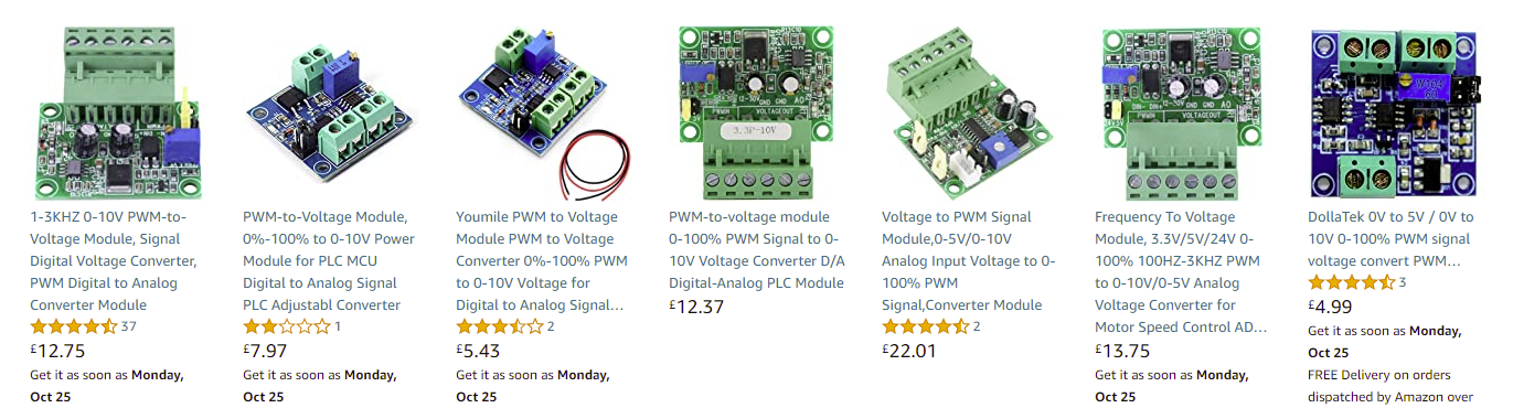
The ones with the square blue PCB have a design flaw (uses an opto isolator, but the input and output grounds are connected together) and should be avoided because (a) they are more difficult to drive from some Duets, and (b) sharing a direct ground connection between a Duet and a high powered brushless motor controller is a bad idea.
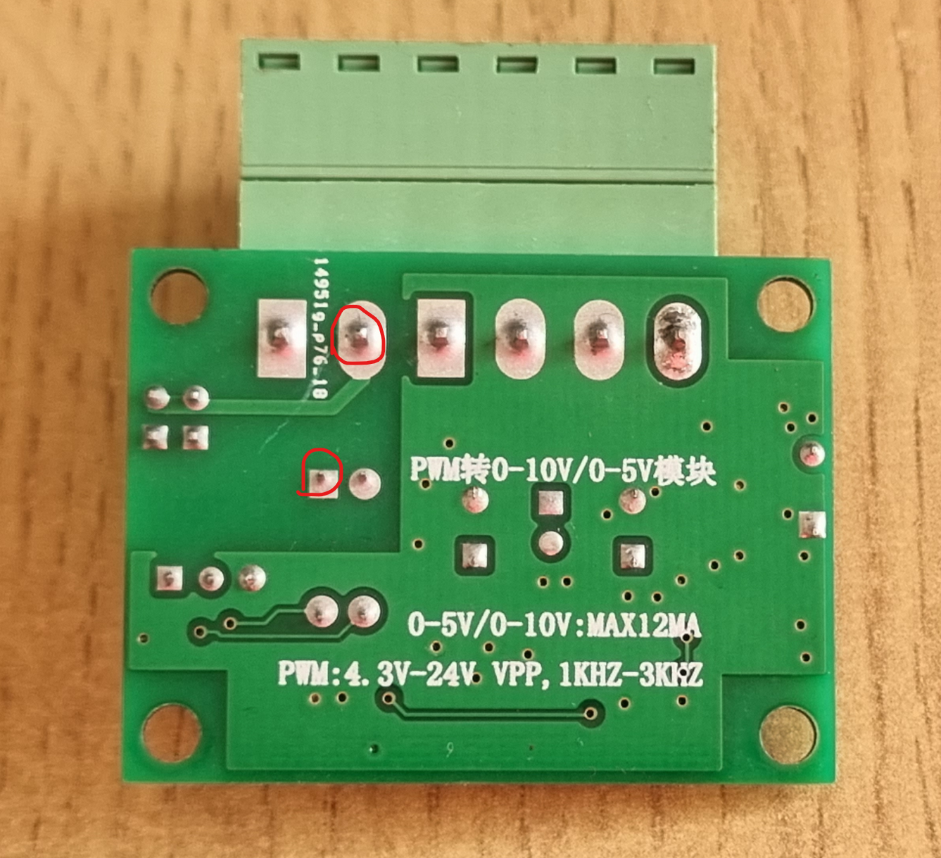
The green sort with the 6-pin pluggable terminal block is the one to use. They have a jumper to select either 5V or 24V input. On the back it says you can use 4.3V to 24V PWM input.
Here are some ways to connect them to a Duet:
-
To a heater or fan output (don't choose FAN1 on a Duet 2 because it defaults to being on). Connect the PWMIN+ input of the converter to the +ve pin of the Duet heater or fan connector (usually labelled VIN or VFAN on the Duet). Connect the PWMIN- pin to the negative pin of the Duet heater or fan output, usually labelled Fan- or Heater- on the Duet. Set the jumper to 24V.
-
To the VFD/LASER output of a Duet 3 or 3 Mini. Connect the PWMIN+ to the OUT pin of the Duet VFD/LASER connector, and PWMIN- to the GND pin of the Duet. Set the jumper to 5V. (edited)
-
The following MIGHT work on a Duet 2 if you have no spare heater or fan outputs. Connect PWMIN+ to +3.3V on the Duet expansion connector, and connect PWMIN- to one of the EnHEAT pins of the expansion connector for some n. Set the jumper to 5V. This only drives the converter with 3.3V.
If #3 doesn't work due to insufficient voltage input from the Duet, try removing the jumper and instead connecting a resistor of about 150 ohms between these two pins.
Don't use this scheme with more than 5V input, because it bypasses the input reverse polarity protection.
¶ Using RS485/Modbus RTU control
From RepRapFirmware 3.6, Duet 3 mainboards (6HC, 6XD and Mini 5+) support the RS485 serial data transmission standard and the Modbus RTU (Remote Terminal Unit) protocol.
Many VFDs support RS485 control of the spindle, and support for a few popular ones has been added by user @NineMile at Millennium Machines. See Connecting RS485 and Modbus RTU devices for details.
¶ Connecting a CNC pendant
Readily-available CNC Pendants can be converted for use with Duet and RRF; see CNC Pendant.