¶ Introduction
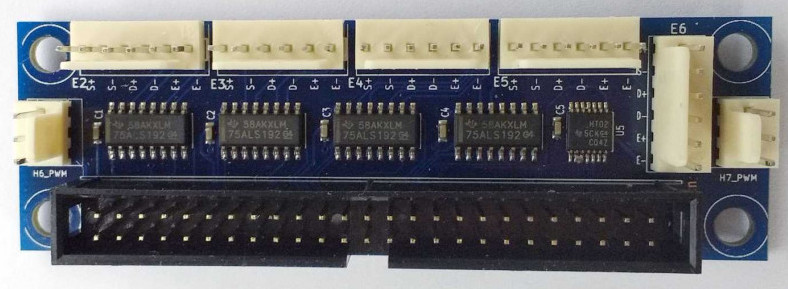
The Duet Expansion Breakout Board (BoB) connects to the Duet 2 (Wifi or Ethernet) expansion header and is specifically designed for external drivers that take differential signals. It also breaks out heater 6 and 7 signals to 5V.
¶ Features
¶ Hardware specification
To do
¶ Operating limits
To do
¶ Firmware notes
The Duet Expansion Breakout Board is compatible with a Duet 2 WiFi/Ethernet board running RepRapFirmware v1.21 and later, including RRF v2 and v3.
¶ Open source
Importantly Duets are Open:
- The Duets are Open Hardware, see our license here
- All hardware source files are available on Github.
- Both the Duet Web Control web interface and RepRapFirmware are Open Source Software with source files available and actively maintained, see Contributing to development for more information.
- The Duet hardware and RepRapFirmware are built with Open tools: designed in KiCad and Eclipse using open tools means the barrier to getting involved is as low as possible.
¶ Physical properties
¶ Dimensions
¶ Mounting
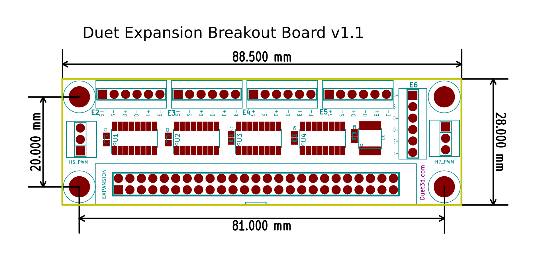
The board has 4 x M4 clearance holes for mounting.
¶ Physical connections
¶ Wiring diagram
¶ Description of connections
A 50 way IDC cable is required to connect the expansion breakout board to a second generation Duet board (Wifi or Ethernet). Note that it is not compatible with first generation Duet boards (0.6, 0.8.5), nor with Duet 3 boards.
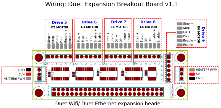
All 5 driver channels provide 3.6V differential signals on ENA-,ENA+, DIR_,DIR+, STEP- and STEP+. Two wires are required for each balanced signal, it is designed to connect to external drivers that take a balanced input, for example the Leadshine DM556 drivers.
Two headers for connecting small hobby servos are also provided.
¶ Pin names
| Pin label on BoB PCB/wiring diagram | RRF3 Pin name (BoB) |
|---|---|
| H6_PWM | exp.heater6, exp.23 |
| H7_PWM | exp.heater7, exp.31 |
¶ Signalling voltages
The Duet Expansion Breakout Board uses a differential output signal of -3.6V to +3.6V. The differential outputs help the LEDs in the optocouplers in most drivers turn off faster. Also they are compatible with drivers that accept RS485 signal levels instead of 5V. Most external drivers are quite happy with the 3.6V differential signals. However, for those few drivers that really do need 5V, you can achieve this by connecting STEP+ from your driver to +5V, which is available on the H6_PWM and/or H7_PWM pin headers (see wiring diagram above), and STEP- for your driver to STEP- on the expansion board. Similarly for DIR and ENA.
¶ Enable signal
Depending on the driver, your ENA input may be a Disable input, not an Enable input. You can fix this by swapping the ENA+ and ENA- wires.
¶ Using the servo headers
Two headers for connecting small hobby servos are available on the Duet Expansion Breakout Board, using Heater 6 and Heater 7 PWM pins. Use them to connect a servo (see Using servos) or as the control for a probe like the BLTouch (see Connecting a Z probe).
Note that the output of the PWM pin is inverted, as it is on the Duex2 and Duex5 expansion board, so any connected servo should have the pin definition inverted. For example, in RRF 3, use:
M950 S0 C"!exp.heater7"
The '!' character in the definition inverts the signal.
¶ Firmware configuration
¶ RepRapFirmware 1.21 onwards, 2.x, 3.x
External drivers are configured using M569 and mapped to axes using M584. The Duet 2 WiFi/Ethernet has five onboard drivers (numbered 0 to 4), and the Duet Expansion Breakout Board allows for the connection of up to five external drivers, numbered 5 to 9. Using M569, define the driver number and stepper driver parameters, then map these drives to the relevant axes, eg:
; Drives
M569 P5 R1 T2.5:2.5:5:5 S1    ; physical drive 5 goes forwards (X)
M569 P6 R1 T2.5:2.5:5:5 S1    ; physical drive 6 goes forwards (Y1)
M569 P7 R1 T2.5:2.5:5:5 S1    ; physical drive 7 goes forwards (Y2)
M569 P8 R1 T2.5:2.5:5:5 S1    ; physical drive 8 goes forwards (Z)

M584 X5 Y6:7 Z8    ; set drive mapping
For more information on how to map axis to these drivers (for example if you want to use external drivers for the X,Y and Z axis) see using external drivers.
¶ References and useful discussion links
solved-leadshine-closed-loop-external-motor-drivers-with-duet2
duet-expansion-board-ena-only-outputs-3-6v
duet-expansion-breakout-board-not-helping-me

