¶ Introduction
If you are planning to use servo motors, or your stepper motors are rated above the current limit of your Duet, or if they need higher voltage than the Duet can provide, then you need external servo or stepper motor drivers. These generally have optically isolated step/dir/enable inputs can usually be controlled with step/direction pulses from a Duet board.
Duet3D sell expansion boards to connect external drivers to Duet mainboards; see Connection options below. This page mainly deals with connecting an external stepper driver to the external driver pins (Duet 3 Mini 5+) or the expansion connector or CONN_LCD pins (Duet 2 WiFi/Ethernet).
See the linked pages for connecting external stepper/servo drivers to Duet 3 Mainboard 6XD, Duet 3 Expansion 1XD and for connecting stepper motors with an encoder for position feedback with the Duet 3 Expansion 1HCL. For Duet 2 there is an Expansion Breakout Board
¶ Duet on-board stepper driver limits
Ideally, motors should be run at between 60% and 85% of their rated current. The table below shows the maximum current and voltage each Duet board can supply to its on-board drivers.
| Max motor current (peak) | Max motor voltage | |
|---|---|---|
| Duet 3 Mainboard 6HC | 6.3A | 48V (v1.01 and earier 32V) |
| Duet 3 Mainboard 6XD | NA | NA |
| Duet 3 Expansion 3HC v1.02 | 6.3A | 48V (v1.01 and earier 32V) |
| Duet 3 Expansion 1HCL | 6.3A | 48V |
| Duet 3 Tool Board 1LC | 1.6A | 32V |
| Duet 3 Expansion 1XD | NA | NA |
| Duet 3 Mini 5+ | 2.0A | 25V |
| Duet 2 WiFi/Ethernet | 2.4A | 25V |
¶ Connection options
There are a number of options available to connect external stepper/servo drivers.
| Pins for direct connection | Provision for additional external drivers | |
|---|---|---|
| Duet 3 Mainboard 6HC | None | CAN bus |
| Duet 3 Mainboard 6XD | Headers for six external drivers with 5V signalling (no on-board drivers) | CAN bus |
| Duet 3 Mini 5+ | External drivers pins (2 drives, 3.3V single-ended signalling) | CAN bus or if only 2 are needed use the Duet 3 Expansion Mini 2XD |
| Duet 2 WiFi/Ethernet | Expansion connector (5 drives, 3.3V single-ended signalling), CONN_LCD (2 drives, 3.3V single-ended signalling) | DueX2/5 (3 spare when used in Duex2 mode, 3.3V single-ended signalling), Duet Expansion Breakout Board (5 drives, differential signalling -3.6V to +3.6V, or 5V single-ended) |
There are two options for Duet 3 CAN-connected expansion boards:
| Provision for external drivers | |
|---|---|
| Duet 3 Expansion 1XD | Single-ended or differential 5V signalling for one external driver. Multiple 1XD boards can be daisy-chained to support as many external drivers as you need. |
| Duet 3 Expansion 1HCL | Stepper driver (6.3A peak, 4.45A RMS) driving a single stepper motor (up to 48V) with encoder. |
The Duet 3 Mainboard 6HC has no on-board external driver pins. Use a CAN bus connected expansion board to provide signalling for the external driver, such as the Duet 3 Expansion 1XD or Duet 3 Expansion 1HCL.
If the drivers require no more than about 2mA @ 3V on the step and dir inputs (there is no enable signal), then you can drive them directly from the Duet 3 Mini 5+ external driver pins. See the Duet 3 Mini 5+ wiring diagram for pin locations. It is recommended to use the Duet 3 Expansion Mini 2XD if you want to connect 1 or 2 external drivers directly to the mini 5+
Otherwise, use a CAN bus connected expansion board to provide signalling for the external driver, such as the Duet 3 Expansion 1XD or Duet 3 Expansion 1HCL.
The Duet 3 6XD supports up to 6 external drivers, see the Duet 3 6XD Documentation for more details. Additional CAN bus connected expansion boards can provide signalling for further external drivers; see Duet 3 Expansion 1XD or Duet 3 Expansion 1HCL.
If the drivers require no more than about 2mA @ 3V on the step, dir and enable inputs, then you can drive them directly from the Duet 2 WiFi/Ethernet Expansion header or CONN_LCD header. The Expansion header has support for 5 external drivers. The CONN_LCD header supports two external drivers.
You can also connect external drivers to the Duet Expansion Breakout Board (EBoB) or DueX2 or DueX5. You can also connect both of the above boards at the same time, using a ribbon cable with a connector in the middle; most of the signals are not connected on the EBoB.
Refer to the Duet 2 WiFi and Ethernet wiring diagram for pinout diagram.
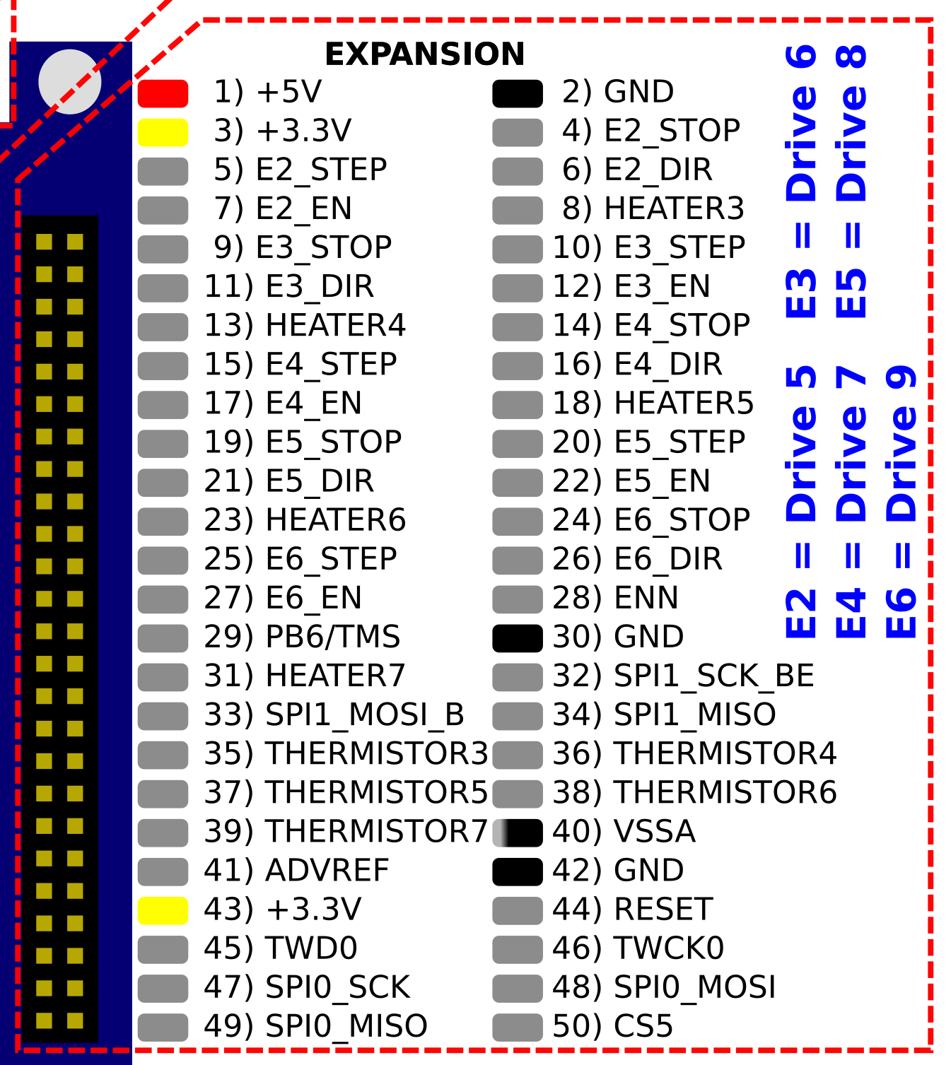
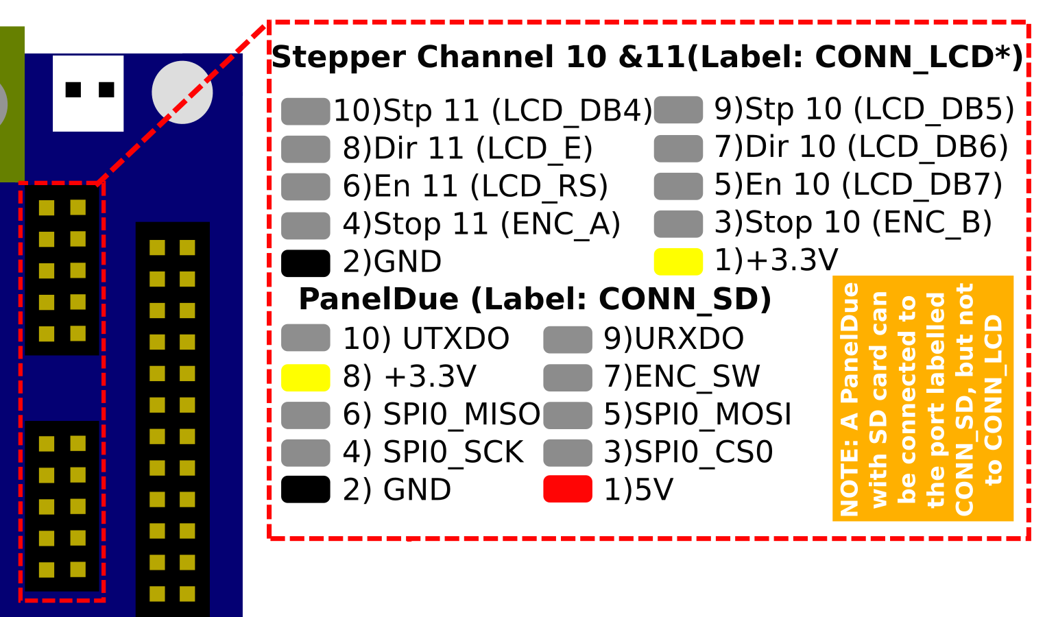
| Driver | Location | Axis name | Endstop pin | Step pin | Direction pin | Enable pin |
|---|---|---|---|---|---|---|
| 5 | Expansion header | E2 | 4) E2_STOP | 5) E2_STEP | 6) E2_DIR | 7) E2_EN |
| 6 | Expansion header | E3 | 9) E3_STOP | 10) E3_STEP | 11) E3_DIR | 12) E3_EN |
| 7 | Expansion header | E4 | 14) E4_STOP | 15) E4_STEP | 16) E4_DIR | 17) E4_EN |
| 8 | Expansion header | E5 | 19) E5_STOP | 20) E5_STEP | 21) E5_DIR | 22) E5_EN |
| 9 | Expansion header | E6 | 24) E6_STOP | 25) E6_STEP | 26) E6_DIR | 27) E6_EN |
| 10 | CONN_LCD | 10 | 3) Stop 10 (ENC_B) | 9) Stp 10 (LCD_DB5) | 7) Dir 10 (LCD_DB6) | 5) En 10 (LCD_DB7) |
| 11 | CONN_LCD | 11 | 4) Stop 11 (ENC_A) | 10) Stp 11 (LCD_DB4) | 8) Dir 11 (LCD_E) | 6) En 11 (LCD_RS) |
You can pick up +3.3V and ground from the Expansion connector and/or CONN_LCD.
Important! External drivers must always be connected to the expansion connector of the Duet or to the CONN_LCD port. The 3-pin pads on the Duet near to the stepper drivers are test pads and are not suitable for connecting external drivers.
¶ Connecting external drivers
¶ Connecting external stepper drivers with differential inputs
These stepper driver modules generally have optically isolated inputs labelled STEP+, STEP-, DIR+, DIR-, ENA+ and ENA-.
If they require no more than about 2mA @ 3V on the step, dir and enable inputs, then you can drive them directly from the expansion connector of the Duet. See the expansion connector pinouts above. Connect STEP+ and DIR+ to your chosen Step and Dir pins on the expansion connector or CONN_LCD, and connect STEP- and DIR- to ground. Connect ENA+ to +3.3V and connect ENA- to your chosen Enable pin.
If you need 5V signalling, you can use 3.3V to 5V level shifting ICs such as 74HCT04 to boost the signal level to 5V and drive them. This is what the Duet Expansion Breakout Board (EBoB) does.
¶ Connecting Pololu-style drivers
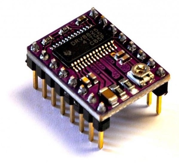
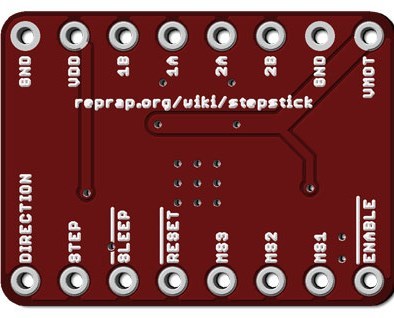
These come in with a variety of different stepper driver chips, but generally have a standard pinout. These take single-ended STEP, DIR and EN (step, direction and enable) signals. For example the popular http://reprap.org/wiki/StepStick has the following pin out:
Even though the stepsticks are nominally 5V boards, nearly all stepper driver chips are specified for 3.3V operation too.
¶ Examples
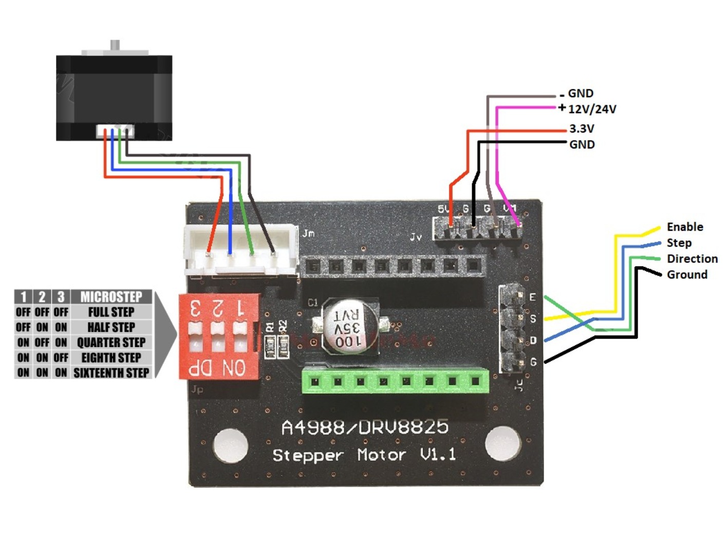
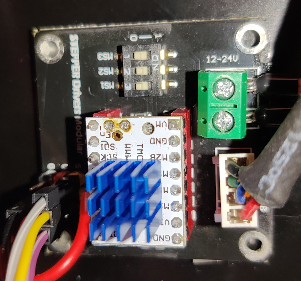
A simple way of connecting an external is to use a stepper driver breakout board such as this one.
Wire as follows:
- 3.3V and GND (Note: The pin labelled 5V on the breakout board must be connected to 3.3V on the Duet, not 5V!)
- 12V/24V (vin) and GND
- ESDG wires (Enable, Step, Direction, Ground)
Note: It’s strongly recommend clearly marking your wires, so as not to short out something or otherwise plug them in improperly!
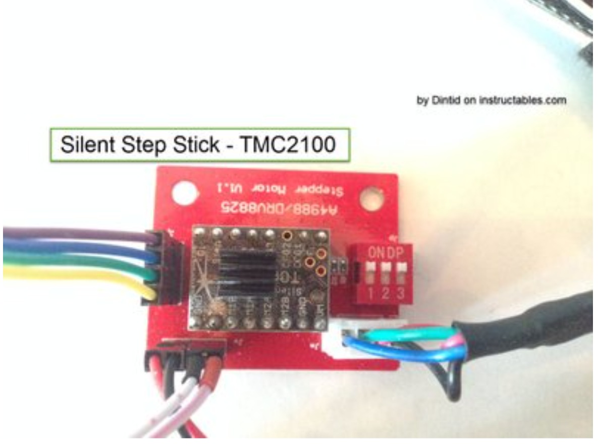
Next, install the Drivers to the breakout board
- The orientation of the drivers is really important. You are going to fry the drivers if they are inserted incorrectly. Remember to always have all power turned off, that includes any USB, whenever you handle the drivers - aside from adjusting the vref.
- The A4988 is inserted with trimpot facing away from dipswitches.
- The DRV8825 is inserted with trimpot facing towards the dipswitches.
- SilentStepStick TMC2100 is inserted with trimpot facing towards the dipswitches.
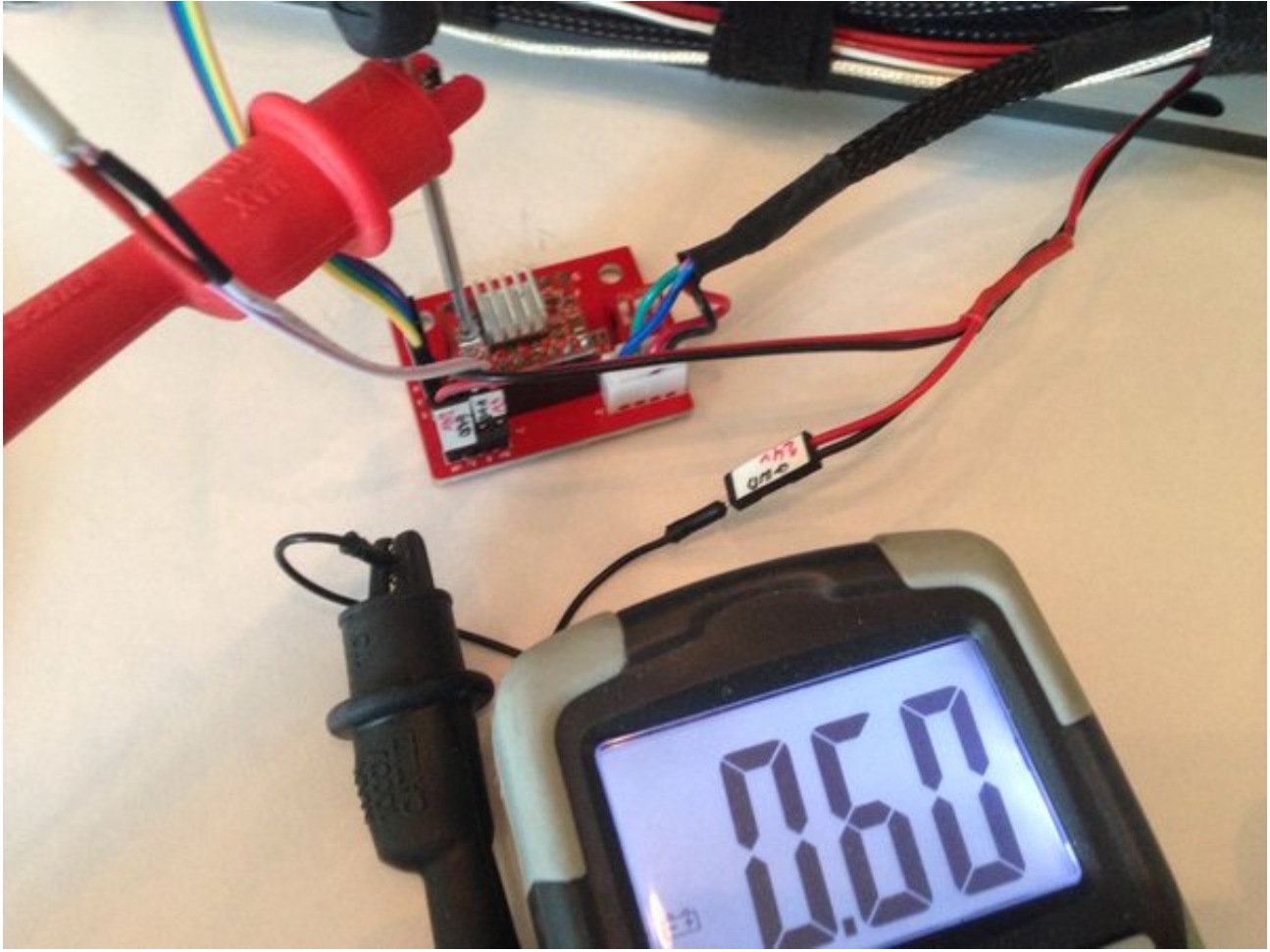
Measure vRef - good practice
- This is not about what value to set it at, but about a good practice to avoid accidents. Use 2 clamps on your Multimeter.
- Connect the black one to a GND on your printer. Easy to use is directly from PSU or from a GND from endstop pins.
- Attach the red one to a small screw-driver fitting for your trimpot.
- This way you have your hands free to actually adjust the trimpot and not having to hold multiple wires and worry about something slipping and making a short circuit somewhere:
This example shows how to add one external stepper driver to drive a third extruder on a Duet 2 Wifi.
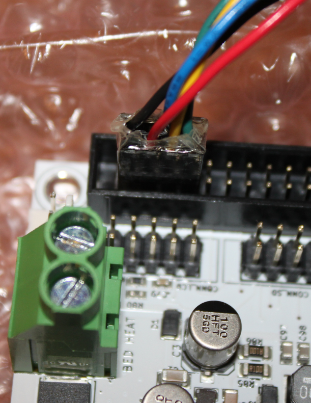
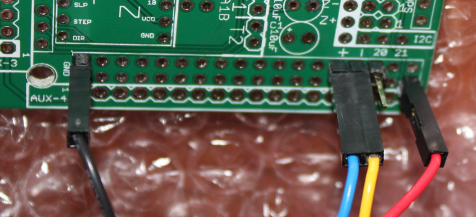
At the Duet 2 Wifi end, connections are made to the GND, +3.3V, E2_STEP, E2_DIR and E2_EN pins on the expansion connector (see table and pinout diagram earlier). A custom cable is made up that connects these pins to the Stepstick.
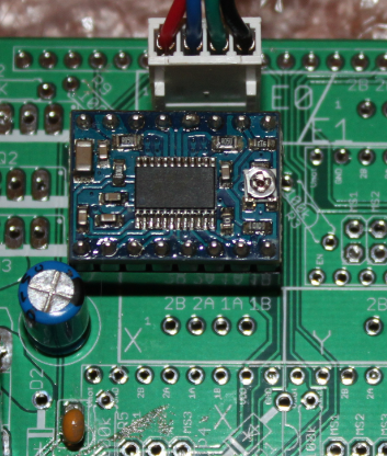
In this example the Stepstick is mounted on on a RAMPS 1.3 pcb, just adding the minimal components needed to support 1 more driver. It was much quicker to use a RAMPS pcb that was spare than to use stripboard to make a custom stepper driver carrier for the stepstick driver, however that is all that the pcb is doing so directly connecting to the stepstick or using a stripboard will also work. It is important to connect a bulk capacitor of ~100uF between power and ground close to the stepstick.
At the RAMPS pcb end:
And the RAMPS PCB with the other components fitted:
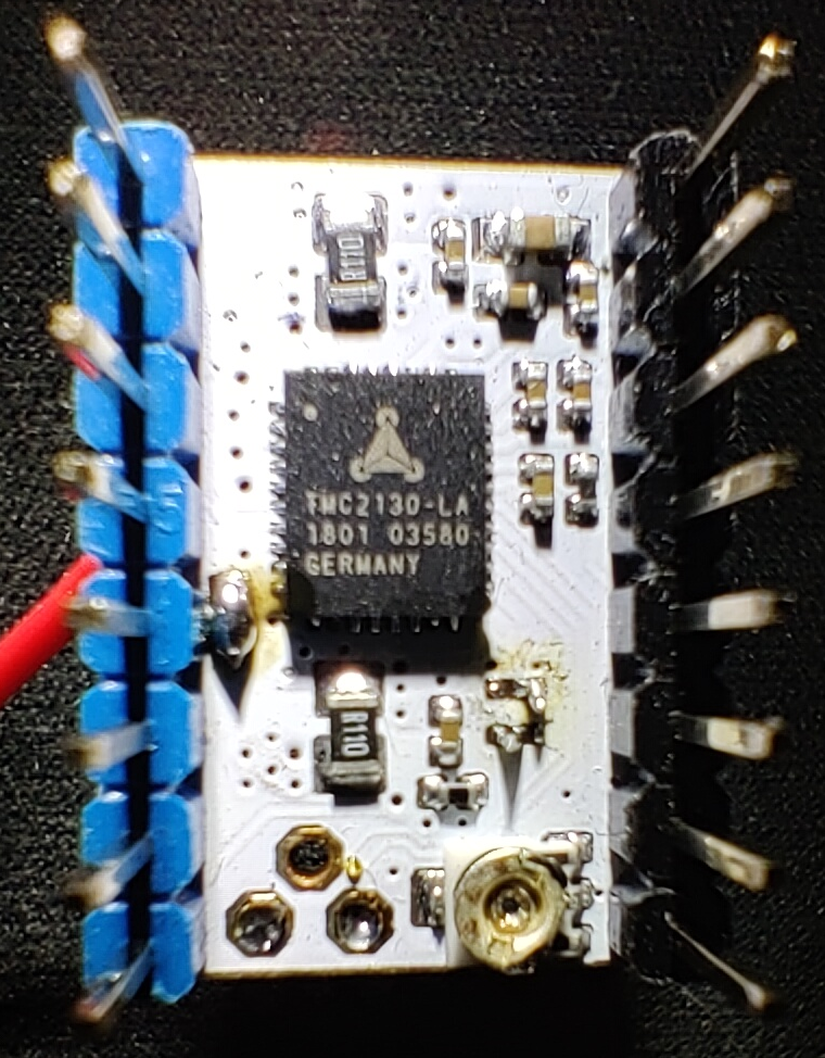
It is possible to use Trinamic stepper drivers in the so called "standalone mode". Since as for now the logic allowing to control the SPI features are not implemented one needs to configure the stepper driver with the CFG pins, those are the pins that would otherwise be used for the SPI interface and are configured with different states: pull up (to VIN), pull down (to GND) or open.
Refer to the TMC2130 board schematics to identify the CFG pins and follow the tables "CFG0", "CFG1 and CFG2" and "CFG3" to set the desired mode as outlined on pages 85-86 of TMC2130 data sheet.
Notice that the order from the top is CFG0, CFG3, CFG2, CFG1
CFG0 - controls the TOFF setting which can help with noise reduction, to achieve the recommended by the datasheet setting this pin needs to be pulled down. On a step stick breakout board like the one from the picture that pin in open, so has to be pulled down to ground, a pin can be soldered up on the step stick.
CFG1 and CFG2 - those two allows to choose the mode of operation - between the StealthChop and SpreadCycle, microsteps and step interpolation. Note that the CFG1 pin is most likely pulled down to ground on your breakout board (with a 10k ohm resistor).
CFG3 - allows to specify the mode of current setting. An open pin allows to set the reference voltage (Vref) with the potentiometer.
There's also the the SPI, CFG4 and CFG5 pins that are on the bottom of the stick. Recommended settings for the CFG4 is pull down to ground and pull up for CFG5. The SPI pads need to be soldered together to disable the SPI mode in favor of the configuration by the CFG pins. The following picture shows how those can be soldered (if there is the need for that - some will already be bridged correctly with 0 ohm resistors).
¶ Noise reduction
If noise is reduced then there are different settings to consider for the CFG pins. 24V power supply (when compared to 12V) reduces noise considerably on it's own. Page 82 of the linked datasheet provides more information about that.
¶ Firmware configuration
¶ Remapping drivers
To use external drivers to drive an axis instead of an internal driver, you need to remap the axis to the external driver using the M584 command. The drive numbers used in G-code correspond to the following driver labels on the board(s):
| Drive number | Duet 3 board label | Duet 2 board label | |
|---|---|---|---|
| Mini 5+ | WiFi/Ethernet | ||
| 0 | DRIVER_0 | X | |
| 1 | DRIVER_1 | Y | |
| 2 | DRIVER_2 | ZA ZB (Two headers wired in series) | |
| 3 | DRIVER_3 | E0 | |
| 4 | DRIVER_4 | E1 | |
| 5 | DRIVER_5 (pins for external driver) | E2 (On Expansion header, DueX2/5 or EBoB) | |
| 6 | DRIVER_6 (pins for external driver) | E3 (On Expansion header, DueX2/5 or EBoB) | |
| 7 | E4 (On Expansion header, DueX5 or BoB) | ||
| 8 | E5 (On Expansion header, DueX5 or BoB) | ||
| 9 | E6 (On Expansion header, DueX5 or BoB) | ||
| 10 | On LCD_CONN header | ||
| 11 | On LCD_CONN header | ||
¶ Configuring the Enable polarity
Only relevant for Duet 3 MB6XD, Duet 3 Expansion Mini 2XD, Duet 3 Expansion 1XD and Duet 2 WiFi/Ethernet. All other boards do not have jumper configurable enable signals.
Duet 3 Mainboard 6XD: See Duet 3 Mainboard 6XD documentation.
Duet 3 Expansion 1XD: See Duet 3 Expansion 1XD documentation.
Duet 2: The Enable signals are active low by default but you can change this using the R parameter in the M569 command.
M569 P5 R1 ; driver 5 requires an active high enable
¶ Configuring the step timing
Refer to the documentation for your stepper driver to determine settings for step timing. The default step timing used for the onboard drivers may be too fast for your external driver. You can set a minimum step pulse width and other timings in the M569 command using the T parameter, and configure the direction with the S parameter.
Taa:bb:cc:dd Minimum driver step pulse width, step pulse interval, direction setup time and direction hold time, in microseconds
M569 P5 R1 T5:5:10:0 ; driver 5 requires an active high enable, 5us minimum step pulse, 5us minimum step interval, 10us DIR setup time and no hold time
¶ Notes on step timing
Where a main board or expansion board drives more than one motor (either directly or via an external driver) and M569 T parameters are applied to more than one motor attached to that board, the M569 T parameters are not settable independently for each motor. Here's how it works:
- Any driver for which the M569 T parameters are all 0.2 or less is a 'fast' driver and will be driven at full speed (with timings not less than 0.2us)
- For the remaining drivers, RRF takes the maximum of each of the four T values, and the resulting set of four T values is applied to all those drivers. RRF does this to speed up the code, because when external drivers are used they are almost always of the same type and so have the same timing requirements.
- On all boards except the MB6XD, when a new M569 T command is processed, RRF updates those maximum values if the T values in the new M569 command are greater. So the set of maximum T values can only increase, not decrease. If you want to reduce the T values, you needs to reboot.
- On the MB6XD the T values are stored independently for each output, and the maximum T vales are recalculated whenever a M569 command with T parameter is processed. So you do not need to reboot if you want to reduce the T values.
- The set of maximum T values is rounded up to the next highest values that RRF can implement. The rounding depends on which board you are using.
- On all Duet 3 boards except the MB6XD and EXP1XD, all four maximum T values are rounded up to the next multiple of 1.33us.
- On Duet 3 MB6XD, if we represent the T parameter as Taa:bb:cc:dd then aa is rounded up to the next multiple of 0.053us, aa+bb is rounded up to the next multiple of 1.33us, cc is rounded up to the next multiple of 1.33us, and aa+dd is rounded to the next multiple of 1.33us.
- Duet 3 1XD is the same as for the 6XD except that aa is rounded up to the next multiple of 0.083us.
- On Duet 2 boards each value is rounded up to the next multple of 1.07us.
You can use M569 with just a P parameter to report the actual timings in use for a driver.
¶ Determining the correct timings to use
The minimum step pulse width aa can be found from the driver datasheet. If the datasheet does not specify the minimum step pulse interval bb then it normally specifies the maximum step rate f and you can calculate bb = (1/f) - aa where f is in MHz. For example, if aa is specified as 2.5us and f is specified as 200kHz (0.2MHz), then bb = (1/0.2) - 2.5 = 2.5us.
If the cables between the Duet and the driver are long and the driver has standard opto-coupled inputs, then the capacitance of the cable may delay the trailing edge of the step pulse, which increases the effective value of aa and reduces the effective value of bb. You may need to increase the value of bb in the M569 command to compensate for this. It's unlikely that you will need to increase aa.
Note, the maximum possible step rate is limited to 1/(aa + bb) MHz. Therefore in order to achieve high step rates, you should not increase the values of aa or bb above the values required by your driver and cabling.
The value required for cc is the direction-change-to-step-pulse setup time specified in the datasheet. If you use a value that is too low for your driver then you may see small layer shifts, where the whole layer shifts by one microstep on each direction change. You may need to use a value higher than specified in the datasheet if the cable capacitance is high. Using a value that is higher than needed is less critical, because RRF will only need to insert delays when the direction changes.
Most drivers do not require a direction hold time from the trailing edge of the step pulse, so cc can be zero unless the datasheet specifies otherwise.
Note that microstepping mode (M350) and driver currents (M906) is not controlled by firmware configuration; it is set by the external stepper driver. Steps per mm (M92), speeds (M566, M203) and acceleration (M201) are controlled by the firmware.
See Configuring stepper motors for examples.
