¶ Introduction
The Duet 2 WiFi and Ethernet are the 2nd generation of Duet 3D motion control electronics. They are an advanced 32-bit controller for 3D printers and other CNC machines.
The Duet 2 Wifi External Antenna and Duet 2 Ethernet are Not Recommended for New Designs. The Duet 2 Wifi with Internal Antenna is End Of Life.
¶ Features
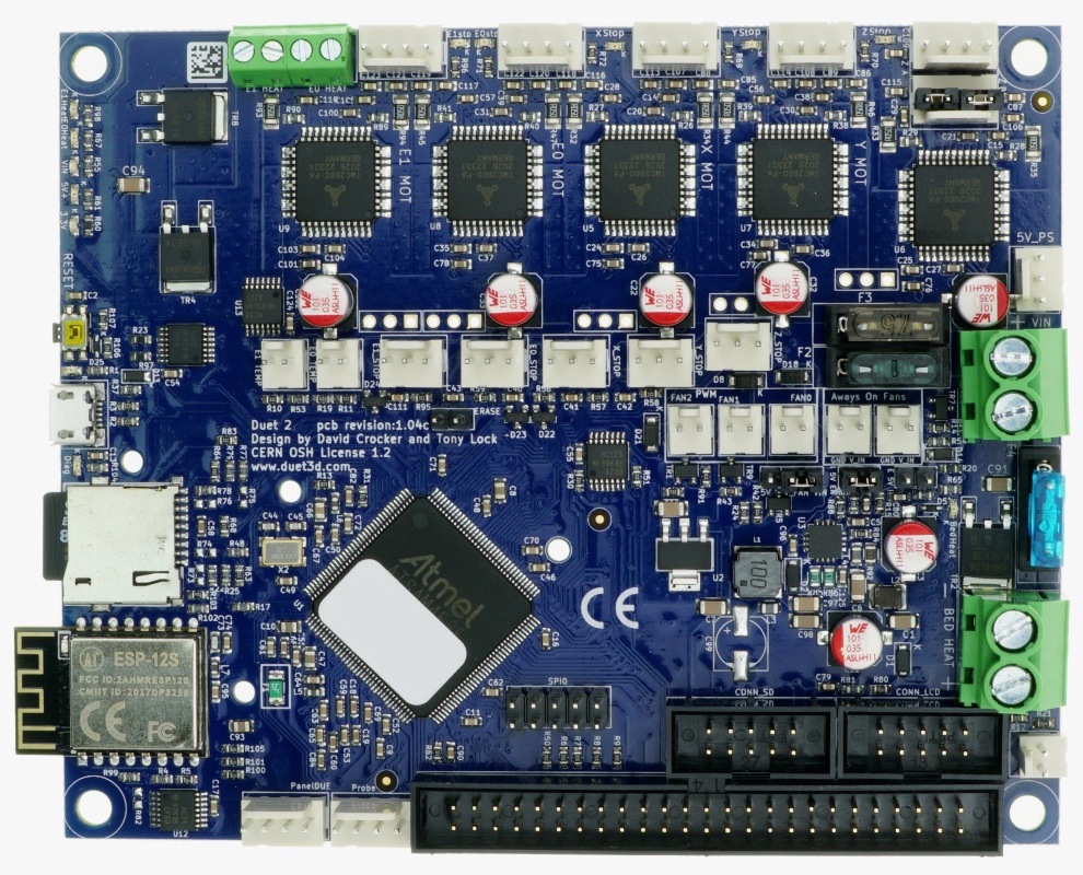
Duet 2 WiFi and Ethernet - main hardware features.
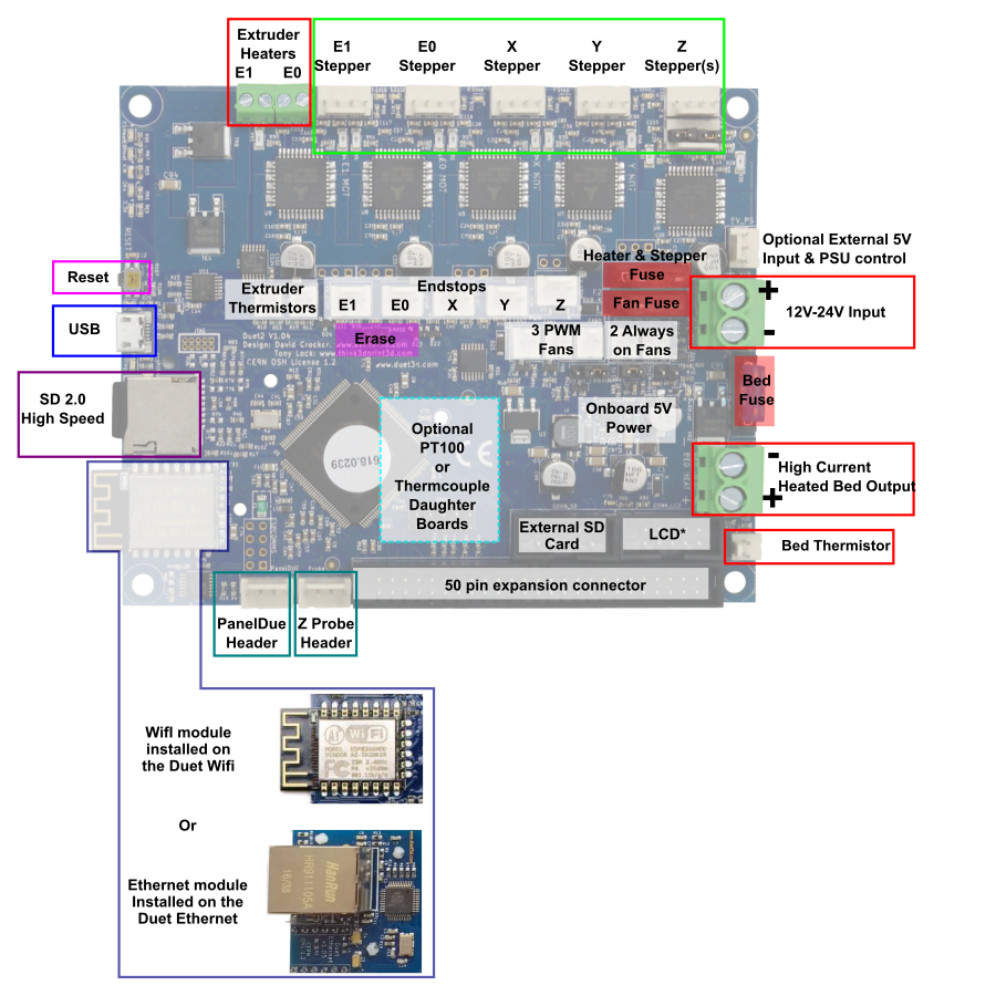
The feature diagram for v1.03 and earlier is below.
¶ Hardware Specification
| Duet 2 WiFi | Duet 2 Ethernet | |
|---|---|---|
| Processor | ATSAM4E8E | |
| Processor features | 120MHz ARM Cortex M4F, 512Kb flash, 128Kb RAM, hardware floating point (single precision), DMA, 2Kb cache | |
| Networking/Comms | 2.4GHz WiFi, WPA-2 encryption; USB port; serial port | 10BaseT/100BaseTX Ethernet; USB port; serial port |
| On-board Stepper drivers | 5 x TMC2660 | |
| Stepper driver features | Up to 2.4A peak current, up to x256 microstepping, optional x16 interpolation on x16 microstepping, stall detection | |
| High current outputs | 1 x 15A1, 2 x 6A each | |
| Medium current outputs | 3 x PWM-controlled outputs, 2 x always-on outputs, voltage selectable between VIN, 5V or external supply (all outputs together), total current limit 1A2; 6 more PWM-controlled outputs on expansion board | |
| Thermistor/PT1000 inputs | 3, optimised for 100k thermistors, can support PT1000 sensors with reduced accuracy | |
| Inputs/Outputs | 5 on-board I/O connectors for endstop and filament monitors (STP pins are 8V-tolerant on revision 1.04 and later), 7 more on expansion header | |
| Endstop or filament monitor inputs | See under Inputs/Outputs | |
| Z probe connector | 4-pin with IN/GND/MOD/3V3 pins (IN pin is 30V-tolerant in revision 1.04 and later) | |
| Endstop status LEDs | Yes | |
| Power monitoring | VIN voltage and input to on-board 5V regulator, allows for state save on power failure. | |
| SD card interface | On-board high speed (20Mbytes/sec) SD card socket. | |
| EXPANSION | |
|---|---|
| Support for attached Raspberry Pi or other Single Board Computer (SBC) | Yes, from RRF 3.2 (requires hardware modification/additional hardware) |
| External stepper driver support | Up to 7 external stepper drivers when not using Duex expansion board. Signal levels are 3.3V. A 5-channel expansion breakout board is available to level shift them to 5V. |
| Stepper driver expansion | Up to 7 additional stepper drivers, of which up to 5 can be TMC2660, as offered by optional DueX5 expansion board |
| PT100 and thermocouple daughter board support | 2 boards (4 channels) |
| Heater/thermistor expansion | 5 more extruder heater outputs and thermistor inputs, 2 more PT100/thermocouple daughter boards (4 channels), offered by optional DueX5 expansion board |
| Servo support | Up to 5 via expansion connector (3.3V drive unless expansion board used) |
| LCD support | PanelDue colour touch screen; 12864 display using ST7567 controller chip (RRF 3.2 and later) |
| Other expansion | 4 GPIO pins on DueX2 and DueX5 expansion board, 16 GPIO pins on third-party SX1509B-based I/O expansion board |
| NOTES |
|---|
| 1 The board is rated to 18A on the bed heater channel, however from version 1.04 forwards they are supplied with a 15A fuse fitted (18A are difficult to source). If you need 18A on the bed heater channel then you need to fit a 20A fuse and take further precautions against over current. |
| 2 The medium current output circuit is fused at 1A. The individual outputs are rated for 1A continuous, but 1.5A for short periods, e.g. fan starting up. The fuse can be increased to 2A as long as the individual outputs will be used within their ratings. |
¶ Operating limits
| Stepper drivers | Up to 2.4A peak current |
| Heater outputs | Bed heater up to 18A, 2 x extruder heater up to 6A each |
| Input power voltage | 11V to 25V1 |
| Input connector rated current | 25A maximum |
| Inputs/Outputs | STP pins are 8V-tolerant on revision 1.04 and later, Z Probe IN pin is 30V-tolerant in revision 1.04 and later |
| Fuses | 15A for bed, 7.5A for stepper drivers and extruder heaters, 1A for fans. |
| 5V current limit | 2.0A total on 5V and 3.3v, including the internal current consumption (around 200-300mA), any PanelDue or other display, and any endstops/Z probes that draw significant power. |
| Maximum ambient temperature | 70°C |
Note: At high currents, it is essential to use either ferrules or solid core wire with the terminal blocks on the Duet 2 and DueX.
1 The maximum recommended power input voltage is 25V. This is a permanent limitation, because the TMC2660 drivers are rated at 30V when supplying power to motors.
¶ Electronics power consumption
When on external 5V power with no connected devices drawing power from the 3.3V or 5V supplies, both the Duet 2 WiFi and Ethernet draw about 200mA average from the 5V supply with the network interface enabled. For the Duet 2 WiFi, the peak current when transmitting may be in excess of 300mA.
¶ Firmware notes
- Compatible RepRapFirmware versions: RRF 2.x, RRF 3.x
- The Duet 2 WiFi has a WiFi module, the ESP8266. This is another 32-bit microcontroller with its own flash storage area, which is where the WiFi connection details are stored. It runs its own firmware, which occasionally needs to be updated. The Duet 2 Ethernet has a W5500 TCP IP processor on board which handles the low level Ethernet networking functions. Installation of both the WiFi and Ethernet modules on the same board at the same time is not supported.
¶ Open Source
Importantly Duets are Open:
- The Duets are Open Hardware, see our license here
- All hardware source files are available on Github.
- Both the Duet Web Control web interface and RepRapFirmware are Open Source Software with source files available and actively maintained, see Contributing to development for more information.
- The Duet hardware and RepRapFirmware are built with Open tools: designed in KiCad and Eclipse using open tools means the barrier to getting involved is as low as possible.
¶ Feature Comparison
See Hardware overview page for a feature comparison table between different versions of the Duet.
¶ Physical properties
¶ Dimensions
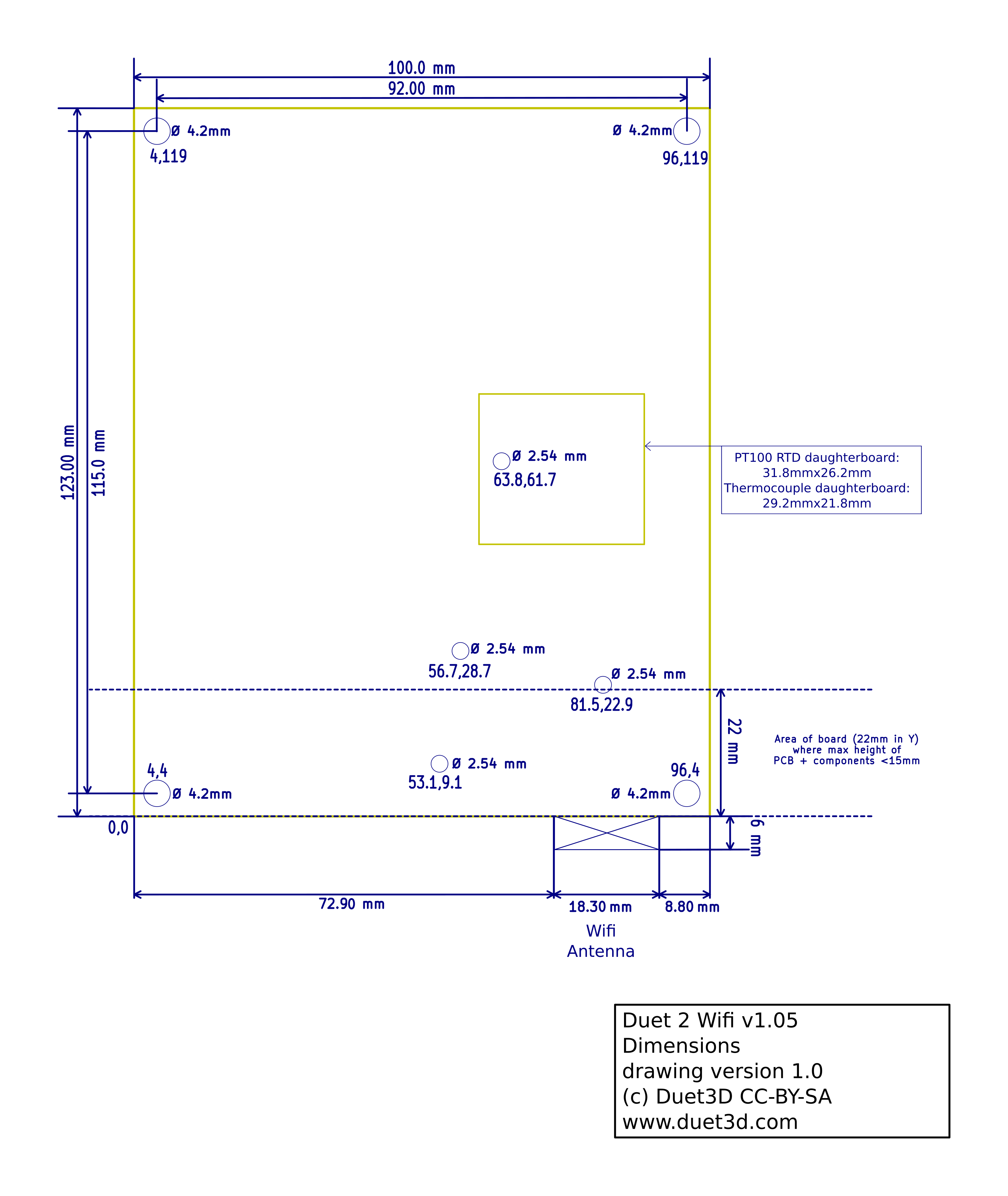
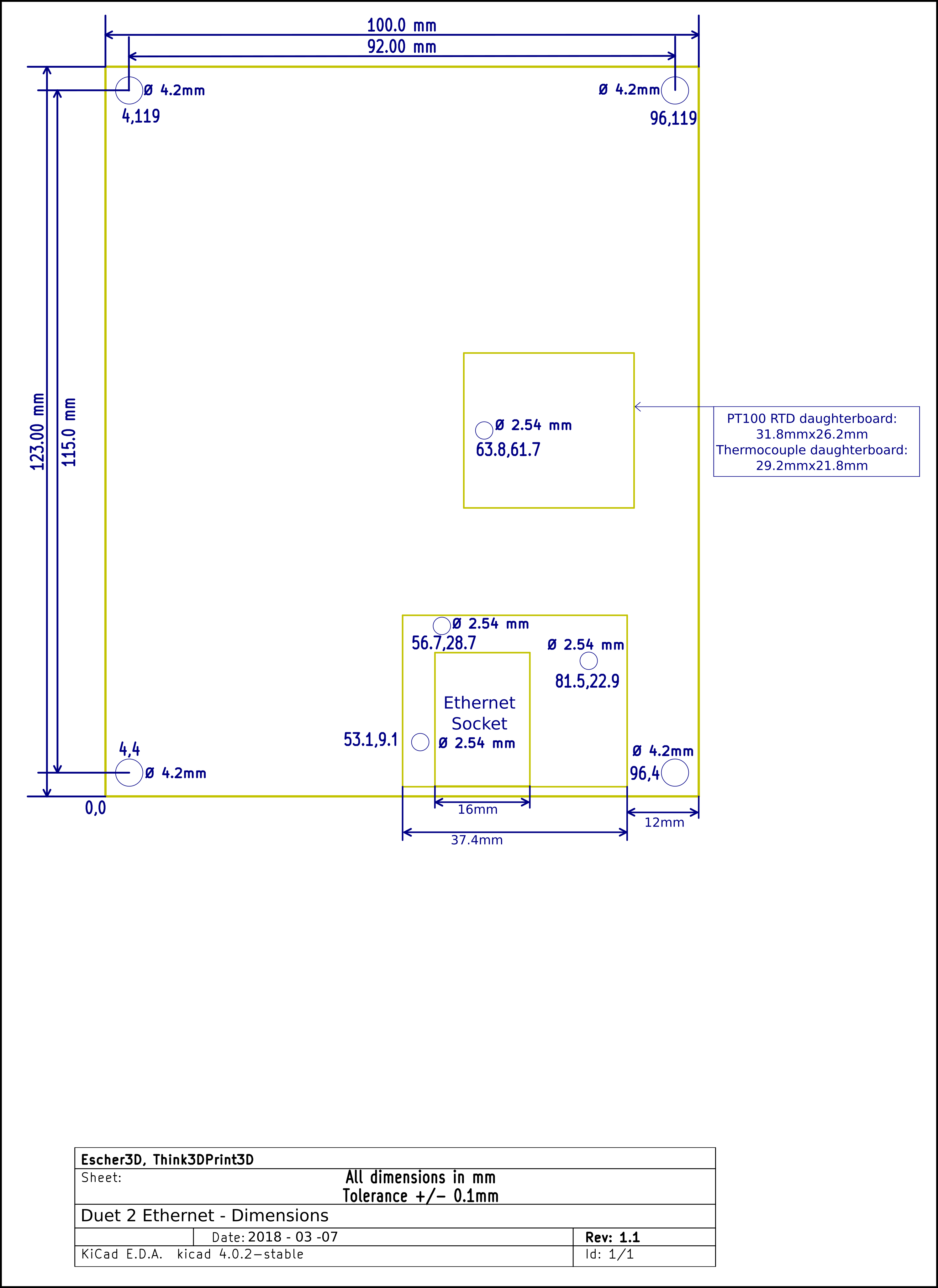
Duet 2 WiFi and Ethernet boards have four 4mm clearance holes at the corners of the board. You can use M4 screws to attach the board to a panel or an enclosure. The hole patterns / mounting centres are 115mm x 92mm.
The diagrams below show the mounting hole points in the format X,Y so the bottom left hole is at X=4mm, Y=4mm, the top left is at X=4mm, Y=119mm and so on. The board has 3 additional 2.54mm holes at: (53.1,9.1),(56.7,28.7),(81.5,22.) for mounting the Ethernet Module.
Note: from v1.05 the WiFi Antenna size on the Duet 2 WiFi internal antenna version has increased slightly
See this image for Duet 2 Wifi dimensions for v1.04c and earlier
¶ Mounting
On Duet 2 WiFi and Ethernet production boards, the holes are isolated and not plated through. On pre-production Duet 2 WiFi boards, the mounting holes are plated-through and connected to the ground plane.
Please note:
- If you mount the board on a metal surface, use standoffs to ensure that the back of the board cannot short against the plate. A minimum standoff length of 5mm is advised, however larger is preferred for better cooling.
- Do not use metal washers under the mounting screws, or screws with large heads (e.g. button head). Nylon washers are recommended. With a metal washer there is a risk of creating a short between the E1 HEAT LED and ground.
¶ Cooling
The PCB is designed to transfer heat from the stepper drivers and power mosfets to the underside of the board. Therefore your mounting method should encourage good airflow underneath the board.
If you mount the board vertically, make sure that cool air can enter at the bottom of the board, flow upwards behind the board, and escape at the top. Convection cooling will usually be sufficient, but if you are using high stepper motor currents then you may wish to add a fan below the board to encourage the upward flow of air. Make the spacing between the back of the board and the panel or enclosure large enough to allow a good flow of air.
If you mount the board horizontally then a cooling fan is recommended, especially if there are other heat-generating components in the vicinity such as power supplies, SSRs or stepper motors. Position the fan to blow air underneath the board (preferably along the top as well), especially along the row of stepper driver chips and between the power input and bed heater terminal blocks.
Important! The higher the motor currents you set, the more important it is to cool the board. Always use a cooling fan if you run a Duet 2 WiFi or Duet 2 Ethernet above 2.0A motor current.
¶ 3D models
Phil Maddox has created a 3d model of the Duet 2 WiFi available here.
Giuliano Moschini has created a model based on the Duet 2 WiFi model for the Duet 2 Ethernet available here
¶ Physical connections
¶ Wiring diagram
¶ Revision v1.0 and later
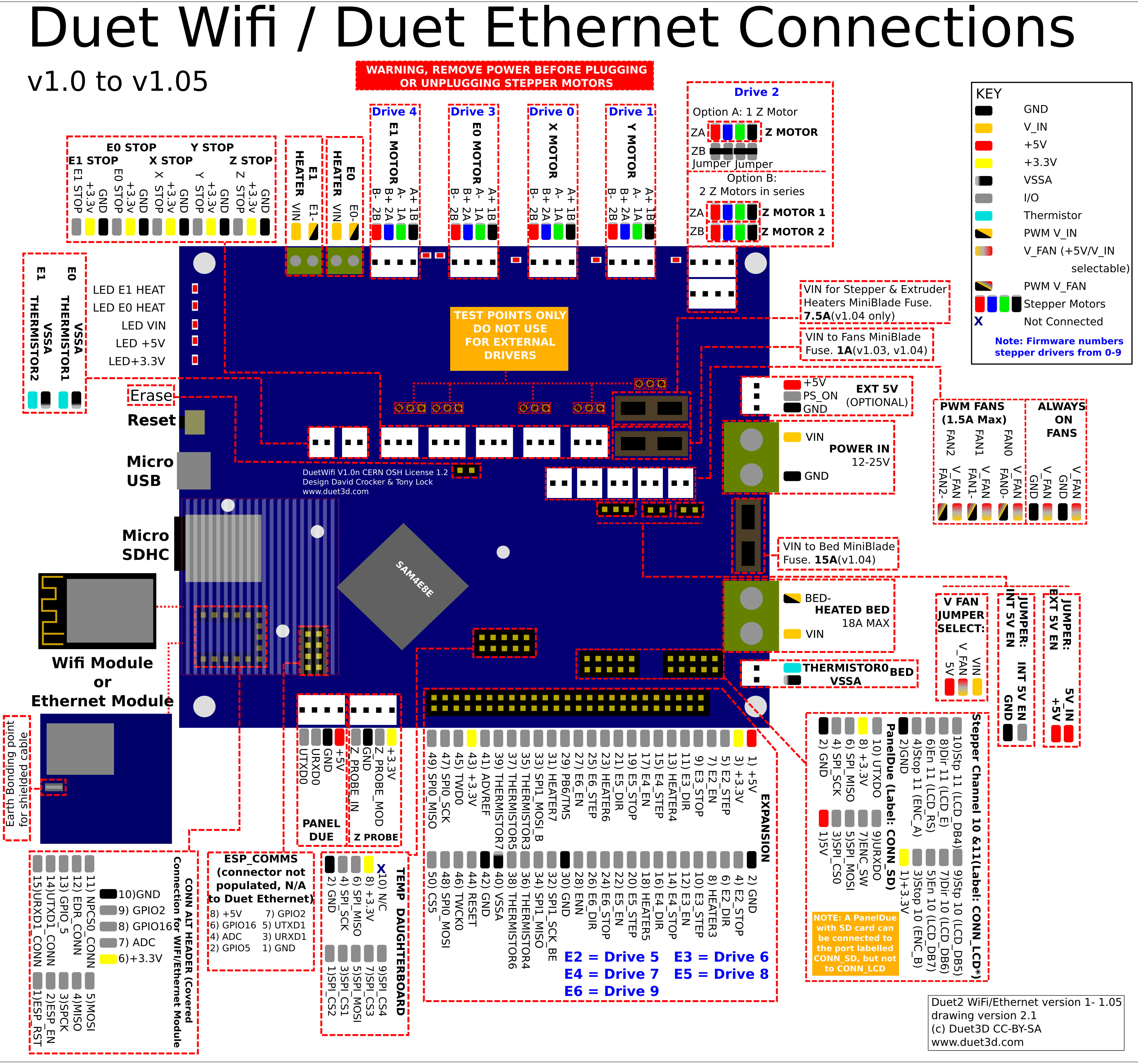
The version 1.0 and later boards is shown in the diagram below.
The .svg version of this diagram is available on github.
¶ Description of Connections
Duet 2 WiFi and Ethernet profide the following connectors:
| Header | PCB label | Function |
|---|---|---|
| 2-way screw terminals, 6.35mm spacing | POWER IN, GND, VIN | Two terminals for main VIN and GND. |
| 2-way screw terminals, 6.35mm spacing | BED HEATER, BED-, VIN | Two terminals intended to drive a bed heater. The ground side BED- is switched by a mosfet and the positive side is protected by a 15A fuse. If using the BED HEATER terminal to drive a SSR, take note that their polarity is opposite to the polarity of the VIN terminals. There is no on-board flyback diode on this output, so if you connect a high-current inductive load, you must use an external flyback diode. |
| 5 x 4-pin KK headers | X MOTOR, Y MOTOR, Z MOTOR, E0 MOTOR, E1 MOTOR | Stepper motor connections. Z MOTOR has two 4-pin KK headers, wired in series, for convenient connection of two Z axis stepper motors to ZA and ZB. If you only have one Z-Axis stepper motor, connect it to ZA connector and ensure jumpers are installed on the ZB connector; without a second stepper motor or the jumpers in place on ZB, ZA will not function. |
| 4-way screw terminals, 3.5mm spacing | E0 HEAT, E1 HEAT | Intended for high current output, eg extruder heaters or fans. Maximum recommended current 6A each. There are no on-board flyback diodes on these outputs, so if you connect a high-current inductive load, you must use an external flyback diode. |
| 3 x 2-pin KK headers | BED TEMP, E0 TEMP, E1 TEMP | Connections for thermistor or PT1000 sensors |
| 5 x 3-pin KK headers | X_STOP, Y_STOP, Z_STOP, E0_STOP, E1_STOP | I/O connectors for endstop and filament monitors |
| 5 x 2-pin KK headers | Always On Fans, FAN0, FAN1, FAN2 | 2 always-on fan connectors, 3 PWM-controlled fan connectors. Voltage selectable between VIN, 5V or external supply (all fans together). Total current draw not to exceed 1A. From board revision v1.02, PWM fan outputs are protected by on-board flyback diodes. |
| 1 x 4-pin KK headers | PanelDue | Connector for 4-wire PanelDue connection |
| 1 x 4-pin KK headers | Probe | Connector for probe with IN/GND/MOD/3V3 pins. NOTE: IN pin is 30V-tolerant in revision 1.04 and later, but only 3.3V-tolerant in revision 1.03 boards and earlier. |
| 1 x 3-pin KK headers | 5V_PS | Used to turn on and off an external 12/24V supply |
| 2x5 header, open | SPIO | This is for connecting PT100 and thermocouple interface boards and/or other SPI connected devices, eg accelerometer. |
| 2 x 10 pin IDC header | CONN_SD, CONN_LCD | Connects the PanelDue UART and shared SPI bus for external SD card. Powered from 5V supply |
| 2x25 header, keyed | EXPANSION HEADER | 50-pin header for connecting DueX5, DueX2 or Duet Breakout Board, for additional stepper motors, heaters, temperature sensors, endstops, probes, fans etc. Pins can also be connected to individually for various additional functionality |
| Network | WiFi: | Blue LED indicates WiFi connection status. |
| Ethernet: | 100BaseT Port (non MDIX). Connect to an Ethernet switch, hub or MDIX enabled laptop port. If connecting to a non MDIX enabled port use a crossover cable. Orange LED on Ethernet port indicates Ethernet enabled, green LED indicates network activity. |
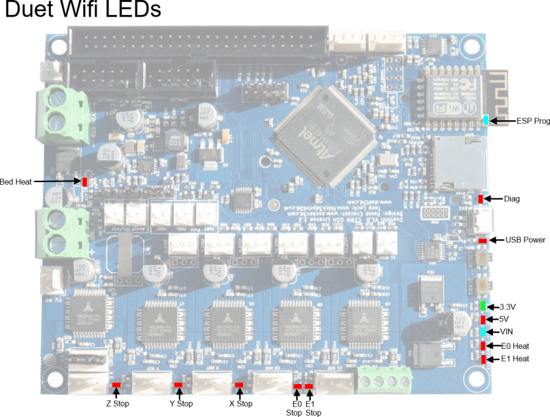
¶ LED indications
The board has a number of on board LEDs which are used to indicate the state of power, endstop switches, heaters etc:
¶ Pin names
For more information on pin names, see Pin Names.
RepRapFirmware 3 uses pin names for user-accessible pins, rather than pin numbers, to communicate with individual pins on the PCB. In RRF 3 no user-accessible pins are defined at startup by default.
For legacy reasons, the pins on the Duet 2 and Duex PCBs and wiring diagram are labelled in a manner similar, but not exactly the same, as the RepRapFirmware 3.x pin name format. For example:
fan2 -> FAN2 etc
ystop -> Y endstop switch, low end, active high
zprobe.in+zprobe.mod -> Z_PROBE_IN and ZPROBE_MOD
exp.heater5 - > HEATER5
Pins can be defined for use by a number of gcode commands, eg M574, M558, M950. Once defined, if you need to free up, for example, the fan 0 pins, use:
M950 F0 C"nil" ; disable fan 0 and free up the associated pin
Or to free up an endstop, send:
M574 X0 P”nil”
In the table below, multiple names on a line are aliases for a single pin. Some pins (primarily heater pins) have an inversion between the processor and the corresponding output, RRF3 will automatically allow for this inversion. These pins are marked with a * after the pin name in the list below. For legacy reasons some Duex pins are inverted or not, depending on the name/alias used to access them. This is indicated with a ! in front of the pin name in the sable below. e.g. exp.heater3 is the same pin as !duex.e2heat the ! indicates that the logic of the pin is inverted when referred to as "duex.e2heat"
| Pin label on Duet PCB/wiring diagram | RRF3 Pin name (Duet) | Notes / Shared with (on Duex/BoB) |
|---|---|---|
| Heater outputs | ||
| BED HEAT | bedheat * | |
| E0 HEAT | e0heat * | |
| E1 HEAT | e1heat * | |
| EXPANSION HEADER HEATER3 (pin 8) | exp.heater3, exp.8 | !duex.e2heat, !duex.pwm1 |
| EXPANSION HEADER HEATER4 (pin 13) | exp.heater4, exp.13 | !duex.e3heat, !duex.pwm2 |
| EXPANSION HEADER HEATER5 (pin 18) | exp.heater5, exp.18 | !duex.e4heat, !duex.pwm3 |
| EXPANSION HEADER HEATER6 (pin 23) | exp.heater6, exp.23 | !duex.e5heat, !duex.pwm4 |
| EXPANSION HEADER HEATER7 (pin 31) | exp.heater7, exp.31 | !duex.e6heat, !duex.pwm5 |
| Temperature inputs | ||
| BED TEMP | bedtemp | |
| E0 TEMP | e0temp | |
| E1 TEMP | e1temp | |
| EXPANSION HEADER THERM3 (pin 35) | e2temp, exp.thermistor3, exp.35 | duex.e2temp |
| EXPANSION HEADER THERM4 (pin 36) | e3temp, exp.thermistor4, exp.36 | duex.e3temp |
| EXPANSION HEADER THERM5 (pin 37) | e4temp, exp.thermistor5, exp.37 | duex.e4temp |
| EXPANSION HEADER THERM6 (pin 38) | e5temp, exp.thermistor6, exp.38 | duex.e5temp |
| EXPANSION HEADER THERM7 (pin 39) | e6temp, exp.thermistor7, exp.39 | duex.e6temp |
| Fan outputs | ||
| FAN0 | fan0 | |
| FAN1 | fan1 | |
| FAN2 | fan2 | |
| Endstop inputs | ||
| X_STOP | xstop | |
| Y_STOP | ystop | |
| Z_STOP | zstop | |
| E0_STOP | e0stop | |
| E1_STOP | e1stop | |
| EXPANSION HEADER E2_STOP (pin 4) | exp.e2stop, exp.4 | |
| EXPANSION HEADER E3_STOP (pin 9) | exp.e3stop, exp.9 | duex.cs6 |
| EXPANSION HEADER E4_STOP (pin 14) | exp.e4stop, exp.14 | duex.cs7 |
| EXPANSION HEADER E5_STOP (pin 19) | exp.e5stop, exp.19 | duex.cs8 |
| EXPANSION HEADER E6_STOP (pin 24) | exp.e6stop, exp.24 | |
| Miscellaneous | ||
| Probe IN | zprobe.in | |
| Probe MOD | zprobe.mod | |
| CONN_LCD ENC_B | connlcd.encb, connlcd.3 | (also used for endstop 11) |
| CONN_LCD ENC_A | connlcd.enca, connlcd.4 | (also used for endstop 10) |
| CONN_SD ENC_SW | connsd.encsw, connsd.7 | |
| EXPANSION HEADER PB6/TMS (pin 29) | exp.pb6, exp.29 | duex.pb6 |
| SPI CS | ||
| SPIO CS1 (Temp DB, pin 3) | spi.cs1 | |
| SPIO CS2 (Temp DB, pin 1) | spi.cs2 | |
| SPIO CS3 (Temp DB, pin 7) | spi.cs3 | |
| SPIO CS4 (Temp DB, pin 9) | spi.cs4 | |
| EXPANSION HEADER CS5 (pin 50) | spi.cs5, exp.50 | duex.cs5 |
| EXPANSION HEADER E3_STOP (pin 9) | spi.cs6, exp.e3stop, exp.9 | duex.cs6 |
| EXPANSION HEADER E4_STOP (pin 14) | spi.cs7, exp.e4stop, exp.14 | duex.cs7 |
| EXPANSION HEADER E5_STOP (pin 19) | spi.cs8, exp.e5stop, exp.19 | duex.cs8 |
| Pins on additional SX1509B expander |
|---|
| See the page on Adding additional output ports for more details. These pins cannot be used to control a laser. |
| sx1509b.0 through to sx1509b.15 |
¶ Input/output
To see where these pins are, see the Wiring diagram section above.
Note: Except for bedheat (VIN), e[0-1]heat (VIN) and fan[0-2] (selectable VIN/5V/external supply), all output pins have 3.3V signal level and there is no protection.
| Pin name (RRF 3.x) | Logical pin (RRF 2.x) | Location/PCB label | Input/Output? | PWM capable? | Servo capable? | Notes |
|---|---|---|---|---|---|---|
| bedheat, e[0-1]heat | 0-2 | Heater connectors | output only | yes | no | Heaters 0-2 on Duet mainboard, VIN |
| exp.heater[3-7] | 3-7 | Expansion header | output only | yes | yes | The outputs on the expansion connector are active low with 3.3V signal level. |
| bedtemp, e[0-1]temp | - | Thermistor/PT1000 headers | input only | no | no | ADC inputs. Has extra latency caused by the RC smoothing circuit for thermistors |
| e[2-6]temp | - | Expansion header thermistor[3-7] (pins 36-39) | input only | no | no | ADC inputs |
| fan[0-2] | 20-22 | Fan connectors | output only | yes | no | Fans 0-2 on Duet mainboard, voltage selectable VIN/5V/external supply |
| [x,y,z,e0,e1]stop | 40-44 | Endstop connectors | input only | no | no | Endstops on Duet mainboard |
| exp.e[2-6]stop | 45-49 | Expansion header | yes | no | no | Additional endstop connections in the expansion connector. |
| exp.pb6 | - | Expansion header PB6/TMS (pin 29) | yes | no | no | Dedicated in RRF 2.x to fan tacho |
| spi.cs1 | - | Temp DB, pin 3 | yes | no | no | |
| spi.cs2 | - | Temp DB, pin 1 | yes | no | no | |
| spi.cs3 | - | Temp DB, pin 7 | yes | no | no | |
| spi.cs4 | - | Temp DB, pin 9 | yes | no | no | |
| spi.cs5 | 60 | Expansion header CS5 (pin 50) | yes | no | no | Signal name: CS5 |
| spi.cs6 | 61 | Expansion header E3_STOP (pin 9) | yes | no | no | Signal name: CS6 |
| spi.cs7 | 62 | Expansion header E4_STOP (pin 14) | yes | no | no | Signal name: CS7 |
| spi.cs8 | 63 | Expansion header E5_STOP (pin 19) | yes | no | no | Signal name: CS8 |
| connlcd.encb | - | CONN_LCD ENC_B (pin 3) | yes | no | no | |
| connlcd.enca | - | CONN_LCD ENC_A (pin 4) | yes | no | no | |
| connsd.encsw | 64 | CONN_SD ENC_SW (pin 7) | yes | no | no | See notes below. Signal name: ENC_SW |
| connlcd.5, connlcd.db7, connlcd.np | - | CONN_LCD pin 5 | yes | no | no | RRF 3.5beta4 and later only |
| connlcd.6, connlcd.rs | - | CONN_LCD pin 6 | yes | no | no | RRF 3.5beta4 and later only |
| connlcd.7, connlcd.db6 | - | CONN_LCD pin 7 | yes | no | no | RRF 3.5beta4 and later only |
| connlcd.8, connlcd.en | - | CONN_LCD pin 8 | yes | no | no | RRF 3.5beta4 and later only |
| connlcd.9, connlcd.db5 | - | CONN_LCD pin 9 | yes | no | no | RRF 3.5beta4 and later only |
| connlcd.10, connlcd.db4 | - | CONN_LCD pin 10 | yes | no | no | RRF 3.5beta4 and later only |
| urxd0 | - | PanelDue Dout | yes | no | no | Available for I/O if PanelDue not enabled |
| utxd0 | - | PanelDue Din | yes | no | no | Available for I/O if PanelDue not enabled |
| pson | - | EXT 5V, PS_ON pin | output only | no | no | Open drain. Available if not controlling PSU |
| zprobe.in | - | Z PROBE header Z_PROBE_IN (pin 1) | input only | no | no | ADC input |
| zprobe.mod | 65 | Z PROBE header Z_PROBE_MOD (pin 3) | output only | no | no | See notes below. Signal name: Z_PROBE_MOD |
| sx1509b.[0-15] | 120-135 | SX1509B expansion I/O pins | yes | yes | no | On an SX1509B-based expander board at I2C address 0x71 connected to a Duet 2 WiFi/Ethernet. See Adding additional output ports |
Notes:
- RRF 3.x - Pull up resistors on Duet 2/DueX5 inputs should be configured for connecting a digital input (like a switch, BLtouch, etc) only on inputs not labelled "n"Stop (xstop, ystop etc).
- RRF 2.x - Logical pin numbers for RRF 2.x are not the physical pin numbers on the expansion header, or the internal pin numbering within the firmware.
- RRF 2.x - Logical pins 64 and 65 are supported in firmware 2.01 and later only. Note that the Z_PROB_MOD pin is driven automatically when some Z probe modes are selected.
- RRF 2.x - Disable a heater using M307 H# A-1 C-1 D-1 to make the pin available, where # is the heater number, and make sure that no tool is configured to use that heater.
- RRF 2.x - Disable a fan using M106 P# I-1 to make the pin available, where # is the fan number.
¶ Power distribution
The Duet boards run on two basic power circuits. The digital electronics are supplied by a 5V circuit, which is internally converted down to the 3.3V levels that drive the MCU. This circuit also drives all the LEDs and sensors, and can be configured to feed the fans. The high-power devices, specifically the stepper motors and the heaters, are powered by a higher voltage, typically 12 or 24 V. This 12/24V circuit can be switched on and off through the PS_ON pin, if the power supply supports this (it may be a good idea to add such support through a relay, for safety reasons, if it doesn't) without interfering with the MCU at all. Alternatively, the Duet boards can draw power from this circuit to power the 5V circuit.
From Version 1.04 onwards the Duet 2 is fitted with 3 blade fuses:
- 1A for the VIN going to the fans
- 7.5A for the VIN going to the heaters and stepper motors
- 15A for the VIN going to the Bed heater
¶ Connectivity
The boards all support connection to a computer over USB, using any standard 3D printer host control program. The Duet 2 WiFi can also connect to a secure WiFi network, while the Duet 2 Ethernet has an Ethernet port. The primary way to control these boards is with a web interface controlled through the network. Although they have removable on-board SD cards, the network interfaces provide fast enough file transfer that it is generally preferable never to remove the on-board SD card.
The boards support a colour touchscreen called the PanelDue. With RepRapFirmware v3.2 and later, it is possible to connect a 12864 LCD screen.
See also:
¶ Motion
The Duet 2 WiFi and Ethernet can drive 5 independent stepper motors. It uses Trinamic TMC2660 stepper drivers, which in addition to the standard step/direction/enable interface provide additional functionality (for example digital current selection and interpolation between microsteps) through SPI. If these chips become damaged or if users wish to use different drivers (for example supporting higher currents) then 5 additional channels of step/direction/enable pins are available on the expansion connector. With the onboard stepper drivers, it is possible to connect multiple motors in series; a connector is provided to make this convenient for the Z axis.
The Duet 2 WiFi and Ethernet provides connectors for one endstop for each axis; these can be simple microswitches (normally open or normally closed) or they can be more complicated boards (for example optical switches) so long as they run off 3.3 V and can provide a digital (on/off) output. Additional endstop pins are available on the expansion connector. Any of these endstop pins can also be configured to trigger user-defined actions, for example as a filament-out sensor or emergency-stop button.
The Duet 2 WiFi and Ethernet also provides a connector specifically for a Z probe. This supports simple switches, boards producing analog outputs (at 3.3 V levels) and boards providing analog outputs that require an on/off modulation signal.
See also:
- Connecting stepper motors
- Connecting endstop switches
- Connecting an Emergency Stop button
- Connecting and configuring filament-out sensors
¶ Heating
The Duet 2 WiFi and Ethernet supports power distribution to and control of three heaters: a heated bed (assumed to be the highest current draw with a maximum of 18A) and two extruder heaters. These are fed from the 12/24V circuit, but the PWM switching is carried out by MOSFETs on the ground, so if necessary they can be run off different voltages. Very high power bed heaters should probably be supplied independently and switched with a SSR.
Alongside each heater there is a temperature sensor input. These can be connected directly to thermistors (whose properties are set in the printer configuration files) or via expansion boards to PT100 sensors or thermocouples.
The Duet 2 WiFi and Ethernet also provides connectors for several fans, some always-on and some PWM-controlled. These can be supplied with 12/24V or with 5V, or (since again the switching is by MOSFETs on the ground line) if necessary from user-supplied power inputs.
See also:
- Connecting thermistors or PT1000 temperature sensors
- Connecting thermocouples
- Connecting PT100 temperature sensors
- Connecting a bed heater
- Connecting and configuring a chamber heater
- Connecting extruder heaters
- Connecting and configuring fans
¶ Expansion
The MCU driving the Duet boards has considerably more inputs and outputs than are used on the main board. Many additional lines are available on the expansion connector.
The DueX2 and DueX5 expansion boards add 2 and 5 extra channels respectively. There are 2 more channels available on the CONN_LCD header, giving a total of 12 stepper channels.
See the Duet 2 WiFi and Ethernet wiring diagrams above for the expansion connector pinout.
¶ PCB revision history
The Duet 2 WiFi and Ethernet both use the same Duet 2 base controller board. The difference is only in the communications module. This base controller board has gone through a number of PCB design revisions. The revision number is marked on the silkscreen on the board, to the left of the large processor chip. The linked page has more information on the Version Numbering system.
The following changes were necessary due to component availability issues, they do not result in functional changes to the design:.
- Changed the 5V buck regulator to AP64200 due to part availability issues.
- Various passive component changes to support the new regulator.
In addition the following improvements to the design were made:
- Split the 5V rail into 5V_INT and 5V_EXT. this provides additional protection to some of the more sensitive components on the board from abuse in the form or feeding >5V into a 5V pin.
- Added TVS diodes to improve ESD protection
- Increase the pad size for the VIN screw terminal pins
On the Duet 2 WiFi internal and external antenna versions the WiFi module changed to an Espressif ESP-WROOM-02D (internal) or 02U (external) module. On the Duet 2 WiFi internal antenna version this change means the size of the internal antenna that projects past the end of the board has increased slightly. See the dimensions section above.
Further minor component value change/tweaks to improve 5V regulator and EMI performance.
Compared to PCB revision v1.03 the following changes have been implemented:
- Provision of a miniblade fuse for the Motors and heaters - Supplied with a 7.5A fuse
- Provision of a miniblade fuse for the Heatbed - Supplied with a 15A fuse.
- The Z probe input improved to tolerate inputs up to 30V.
- The endstop inputs will tolerate at least 8V.
- Replaced erase switch with an erase jumper
- Changes to some layouts, and trace routing to further improve EMI performance.
- On 1.04a and later the JTAG header is removed
Source files available here.
Note: 1.04 Duet WiFi/Ethernet boards manufactured in June/July 2018 had the incorrect resistor value fitted at position R107 (10K instead of 100R). On these boards, the external reset pin on the expansion connector will not work. This can be remedied by soldering a 100R 0603 resistor on top of the existing one at position R107.
The feature diagram for PCB revision v1.03 and earlier is below
Compared to PCB revision v1.02 the following changes have been implemented:
- The Fan MOSFETS now have a miniblade fuse in the VIN supply (not 5V supply).
- Each of the TMC2660s Stall Guard outputs is ORd together and fed to the MCU. This allows for quicker reaction to SG signals.
- Minor routing changes
Source files available here
Compared to PCB revision v1.01 it had the following changes:
- Changed to a resettable VSSA fuse. Now if the thermistor inputs are connected to VIN, the VSSA fuse should reset rather than needing to be replaced.
- Added capacitors on stepper driver outputs to reduce EMI and improve protection against inductive transients.
- Added flyback diodes to the PWM fan outputs to protect against non brushless DC fans/pumps.
- Minor routing changes.
Source files available here
Compared to PCB revision v1.0 it had the following changes:
- Minor routing changes
- The filter capacitors for the ADC inputs are connected to main ground, to better protect the MCU if the VSSA fuse blows
- Note: (There is an error on v1.0 and v1.01 on the silkscreen where the E0-/E1- and VIN are reversed - use the diagram above rather than the silkscreen. This is fixed in v1.02 boards)
Source files available here
The first production version. Compared to the prototype it had the following changes:
- ESP_COMMS Header breaks out all the spare ESP pins.
- Added test points for Step,Dir and CS for the onboard stepper drivers.
- Top and bottom copper layer thicknesses increased to 2oz
- Added a global enable signal for the TMC2660 drivers
- Minor routing changes.
- Note: (There is an error on v1.0 and v1.01 on the silkscreen where the E0-/E1- and VIN are reversed - use the diagram above rather than the silkscreen. This is fixed in v1.02 boards)
Source files available here
This board is identifiable by the white solder-mask (all other boards are blue) it was made in a limited production run compared the version.
- On the white pre-production boards in some wiring configurations, if you reset the Duet 2 WiFi by pressing the Reset button when the motors are energised, then the stepper motors may move while the Reset button is held down. This is fixed in the production boards.
For the initial beta testers who have the old WHITE pre-production boards the pin out is below. The differences from the production boards are:
a) probe connector reversed.
b) SD and LCD connectors reversed.
c) endstop connectors reversed.
The linked diagram is for white pre-production Duet WiFi boards only!
