¶ Duet on-board stepper drivers
¶ Stepper driver provision
The Duet 3 Mainboard 6HC has 6 on-board stepper drivers. Duet 3 Mini 5+, Duet 2 WiFi, Ethernet and Maestro all have 5 on-board stepper drivers. To see the exact location of the pins check the wiring diagrams here:
Duet 3 Mainboard 6HC wiring diagram
Duet 3 Mini 5+ wiring diagram
Duet 2 WiFi/Ethernet wiring diagram
Duet 2 Maestro wiring diagram
Additional stepper drivers can be added:
- For Duet 3 this is done using CAN expansion boards such as Duet 3 Expansion 3HC and Duet 3 Toolboard 1LC, and/or connect extra mainboards configured as a CAN-connected slaves.
- The Duet 3 Mini 5+ can have an additional two drivers on-board, using the Duet 3 Expansion Mini 2+, as well as CAN-connected boards.
- The Duet 2 WiFi/Ethernet supports the DueX2/5, which adds a further 2 or 5 stepper drivers, connected by the expansion port.
- The Duet 2 Maestro supports an additional two drivers on-board, using the Dual Stepper Driver Expansion Module.
Duet 3 Expansion 3HC wiring diagram
Duet 3 Toolboard 1LC
Duet 3 Expansion Mini 2+
Duet 2 DueX2/5 wiring diagram
Dual Stepper Driver Expansion Module
¶ Using the internal drivers
To connect stepper motors to the internal drivers, refer to the wiring diagram for your board. The pinout of each stepper motor connector is the same as for other popular 3D printer electronics.

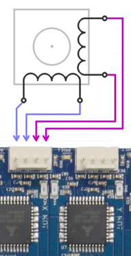
For ALL DUETS, you must connect the two wires for one phase of the stepper motor to the two pins at one end of the connector, and the wires for the other phase to the two pins at the other end.
See the next section to identify your motor's phases.
Each stepper motor connector has four pins.
On Duet 3 and Duet 2 Maestro, the four motor connector pins are labelled 'B1 B2 A1 A2' on the back of the board and on the wiring diagram. The 'A' and 'B' refer to the coil or phase, the '1' and '2' refer to the positive and negative. This is the naming convention used by most stepper motor manufacturers.
On Duet 2 WiFi/Ethernet these are labelled '2B 2A 1A 1B' on the back of the board, and on the wiring diagram. The '1' and '2' refer to the coil or phase, the 'A' and 'B' refer to the positive and negative.
Caution! Mixing the phases up on the 4-pin connector can and often does result in damage to the stepper driver. So make sure that you know which pairs of wires belong to the same phase. It doesn't matter which phase you connect to which pair of pins, or which way round you connect each phase: swapping the two phases over or swapping the pair of wires in a phase simply causes the motor to turn the other way, which you can correct in the config.g file.
Be especially careful when using stepper motors with detachable cables! A Nema 17 motor with a detachable cable usually has a 6-pin JST connector on it, but different manufacturers use different pinouts on that connector. Always check the stepper motor phases (see next section) when using motors with detachable cables.
It is highly recommended that the stepper motor casings be grounded, especially in belt-driven printers. Otherwise, motion of the belts causes static charge to build up, which eventually arcs over to the windings. Filament motion in extruders can cause static charge to build up on the extruder drive motor too. If the motors are screwed to a metal frame, grounding the frame is sufficient.
¶ Identifying the stepper motor phases
Here are two ways you can pair the stepper motor wires into phases:
- Use a multimeter. There should be a few ohms resistance between two wires that belong to the same phase, and no continuity between wires that belong to different phases.
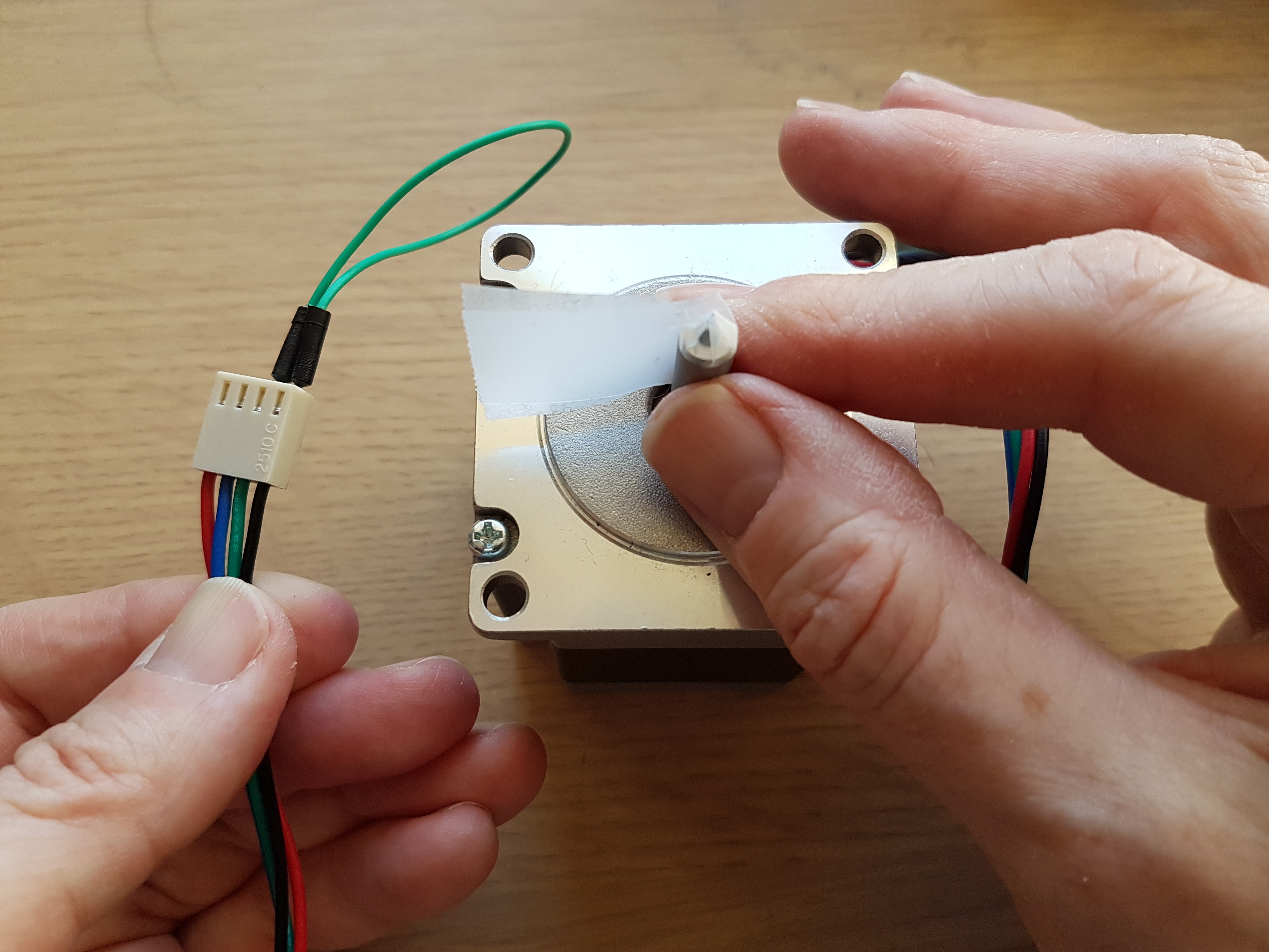
- With the motor wires not connected to anything, spin the spindle between your fingers. Short two of the wires together, then spin the spindle again. If it is much harder to spin than before, those two wires belong to the same phase. Otherwise, try again with a different pair of wires shorted together.

¶ Connecting multiple motors on an axis
¶ Duet 3
If you have two stepper motors for an axis that you want to drive together, for example two motors for the Z axis, then for the types of motors commonly used in RepRaps (i.e. with rated current in the 1.2 to 2.0A range), it is better to connect them in series than in parallel. Google "wiring stepper motors in series" for instructions on how to do this, for example this Instructables guide.
Some recent Chinese 3D printer kits have low-current Z stepper motors that are designed to be connected in parallel instead. If the motors have a rated current of 1.0A or below, connect them in parallel.
¶ Duet 2 (WiFi, Ethernet and Maestro)
If you have two stepper motors for one axis, connect them to the ZA and ZB connectors. These connectors are wired in series, which is better than wiring them in parallel for most types of stepper motor used in 3D printers.
If you have only one Z stepper motor, plug it in to the ZA connector, and plug two jumpers into the ZB connector. Duet 2 boards are normally supplied with these jumpers already fitted.
¶ Multiple independent motors on an axis
Alternatively, if you have a spare unused stepper driver, you can connect each stepper motor on the axis to it's own stepper driver. This allows for each motor to move independently, which is useful for levelling or straightening the axis. For example, you might have two or three stepper motors that move the Z axis up and down, or have a CNC machine where there are two motors for the Y axis, one each side. See the following documentation for setting this up: Configuring stepper motors.