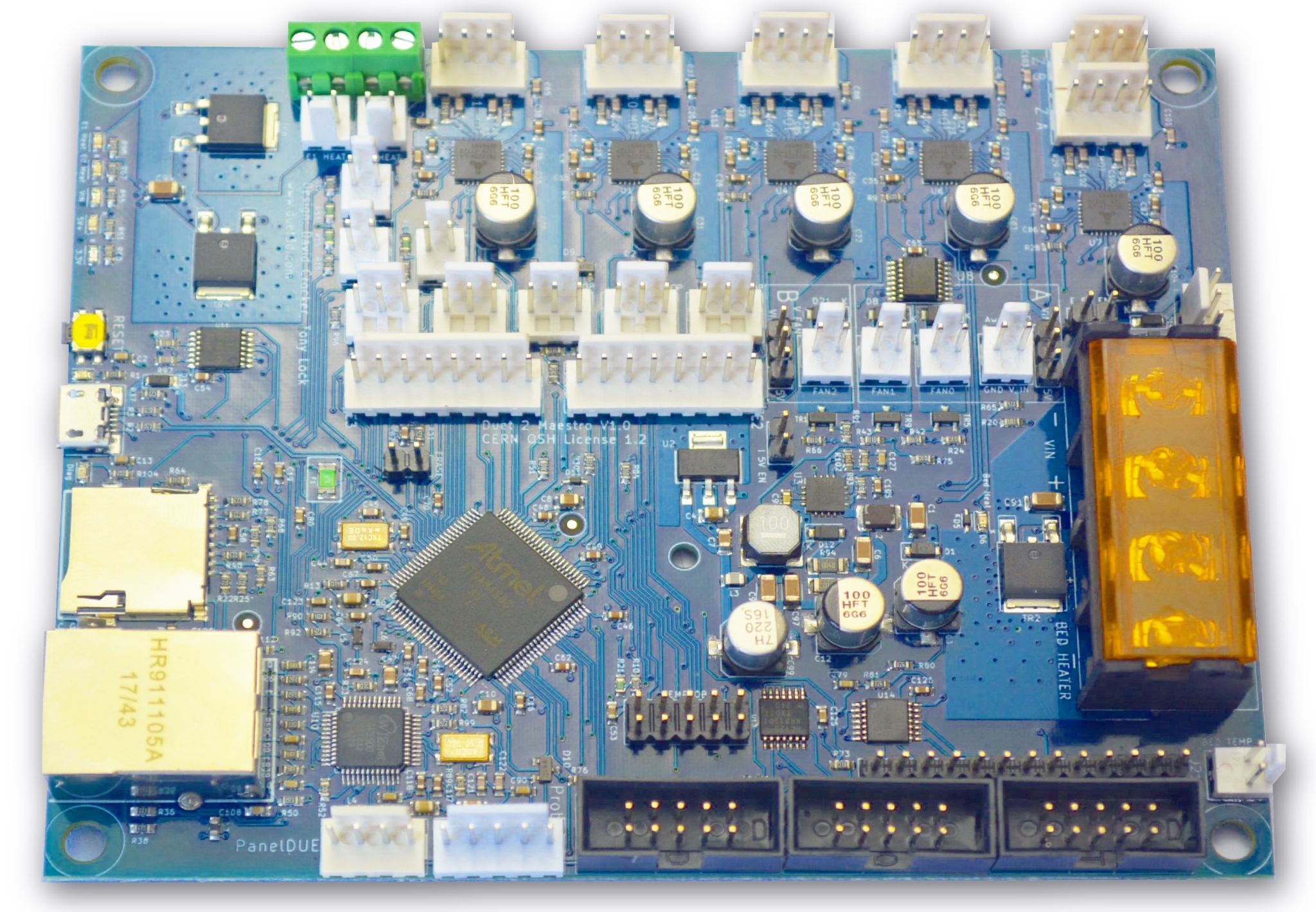
¶ Introduction
Overview of Duet 2 Maestro hardware
¶ Features

The main hardware features of the Duet 2 Maestro are listed below
¶ Hardware specification
| Duet 2 Maestro | |
|---|---|
| Processor | 32-bit 120MHz ARM Cortex-M4 microcontroller, SAM4S8C |
| Processor features | 512Kb flash memory, 128Kb RAM, DMA and many peripherals. |
| On-board stepper drivers | 5x Super quiet TMC2224 stepper drivers. |
| Stepper driver features | Up to 1.6A peak current, optional step interpolation from any lower microstepping setting to x256, SPI-controlled, stealthChop2 |
| Heater outputs | 3 heater channels for a heated bed and dual extruders |
| Thermistor/PT1000 inputs | 4 temperature sensor channels, optimised for 100K thermistors and PT1000 sensors |
| Fan outputs | 3 PWM controlled fan connectors, 1 always-on fan connector. Voltage selectable between VIN, 5V or external supply, in 2 banks |
| Endstop or filament monitor inputs | 5 on-board |
| Z probe connector | 5-pin with IN/GND/MOD/3V3/5V pins |
| Networking/Comms | Dedicated 10BaseT/100BaseTX Ethernet module; USB port; serial port. |
| SD card interface | On-board high speed (15Mbytes/sec) SD card socket. Support for an optional external SD card socket. |
| Power monitoring | VIN voltage monitoring allows for state save on power failure. |
| EXPANSION | |
|---|---|
| Stepper driver expansion | Headers for two external stepper drivers with step/direction/enable interface and optional configuration via single wire UART (TMC2208 or TMC2224). |
| PT100 and thermocouple support | Add-on daughter board available for PT100 or thermocouple support. Up to 2 daughter boards (4 channels) supported (second board available only if I2C expansion pins are not used) |
| Servo support | One hobby servo output on the expansion header with 5V drive (shares the output with the Z probe MOD pin and the diagnostic LED) |
| Z probe support | Support for a wide range of probes; IR sensors, BLTouch, Piezo, force-sensitive, inductive or capacitive probes. |
| Filament monitor support | Support for the Duet3d Filament Monitor both magnetic and laser versions. |
| LCD support | Dedicated connectors for PanelDue controller (full colour graphic touch screen controller) and 12864 mono graphics display (using ST7920 controller with 5V signal levels) |
| Other I/O | 2 pins usable as analog inputs, GPIO, or UART. 2 pins usable as I2C or GPIO. |
¶ Notes
Discontinued: Duet 2 Maestro discontinued June 2020
DueX compatibility The DueX2/5 boards designed for the Duet 2 WiFi and Duet 2 Ethernet are not compatible with the Duet 2 Maestro.
¶ Operating limits
| Stepper drivers | Up to 1.6A peak current |
| Heater outputs | Bed heater up to 18A, 2 x extruder heater up to 6A each |
| Input power voltage | 11V to 25V |
| Input connector rated current | 25A maximum |
| Endstop/filament monitor inputs | STP pins are 30V-tolerant |
| Z probe connector | IN pin is 30V-tolerant |
| 5V current limit | 2.0A total on 5V and 3.3v, including the internal current consumption (around 200mA), any PanelDue or other display, and any endstops/Z probes that draw significant power. |
| Maximum ambient temperature | 70°C |
¶ Firmware notes
- Compatible RepRapFirmware versions: RRF 2.x, RRF 3.x up to 3.5.x. Not supported in RRF 3.6.0 or later because the MCU on the Maestro does not have floating point hardware.
¶ Open Source
Importantly Duets are Open:
- The Duets are Open Hardware, see our license here
- All hardware source files are available on Github.
- Both the Duet Web Control web interface and RepRapFirmware are Open Source Software with source files available and actively maintained, see Contributing to development for more information.
- The Duet hardware and RepRapFirmware are built with Open tools: designed in KiCad and Eclipse using open tools means the barrier to getting involved is as low as possible.
¶ Feature Comparison
See Hardware overview page for a feature comparison table between different versions of the Duet.
¶ Physical properties
¶ Dimensions
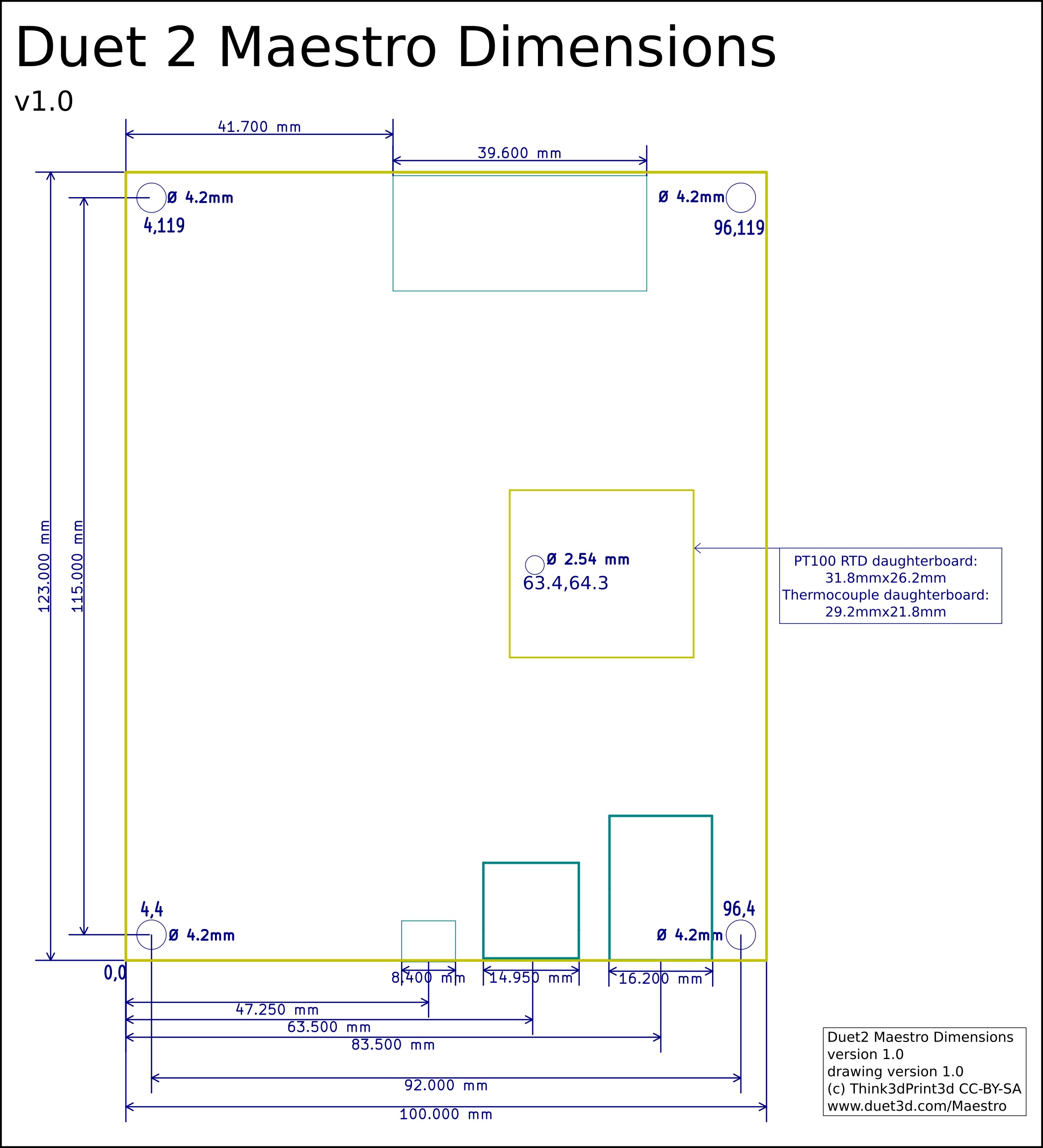
There are four 4mm clearance holes at the corners of the board. You can use M4 screws to attach the board to a panel or an enclosure, make sure to use nylon washers under the screw heads. The mounting centres are 115mm x 92mm, full dimensions are shown in the diagram:
Duet 2 Maestro Dimensions
The diagrams show the mounting hole points in the format X,Y so the bottom left hole is at X=4mm, Y=4mm, the top left is at X=4mm, Y=119mm and so on. The board has 1 additional holes at (63.4,64.3) for mounting the temperature daugherboard.
¶ Mounting
The mounting holes are isolated and not plated through.
Please note:
- If you mount the board on a metal surface, use standoffs to ensure that the back of the board cannot short against the plate. A minimum standoff length of 5mm is advised, however larger is preferred for better cooling.
- Do not use metal washers under the mounting screws, or screws with large heads (e.g. button head). Nylon washers are recommended. With a metal washer there is a risk of creating a short.
¶ Cooling
The PCB is designed to transfer heat from the stepper drivers and power mosfets to the underside of the board. Therefore your mounting method should encourage good airflow underneath the board.
If you mount the board vertically, make sure that cool air can enter at the bottom of the board, flow upwards behind the board, and escape at the top. Convection cooling will usually be sufficient, but if you are using high stepper motor currents then you may wish to add a fan below the board to encourage the upward flow of air. Make the spacing between the back of the board and the panel or enclosure large enough to allow a good flow of air.
If you mount the board horizontally then a cooling fan is recommended, especially if there are other heat-generating components in the vicinity such as power supplies, SSRs or stepper motors. Position the fan to blow air underneath the board (optionally along the top as well), especially along the row of stepper driver chips and between the power input and bed heater terminal blocks.
Important! The higher the motor currents you set, the more important it is to cool the board.
¶ 3D model
A 3d model of the Duet 2 Maestro has not yet been produced.
¶ Physical connections
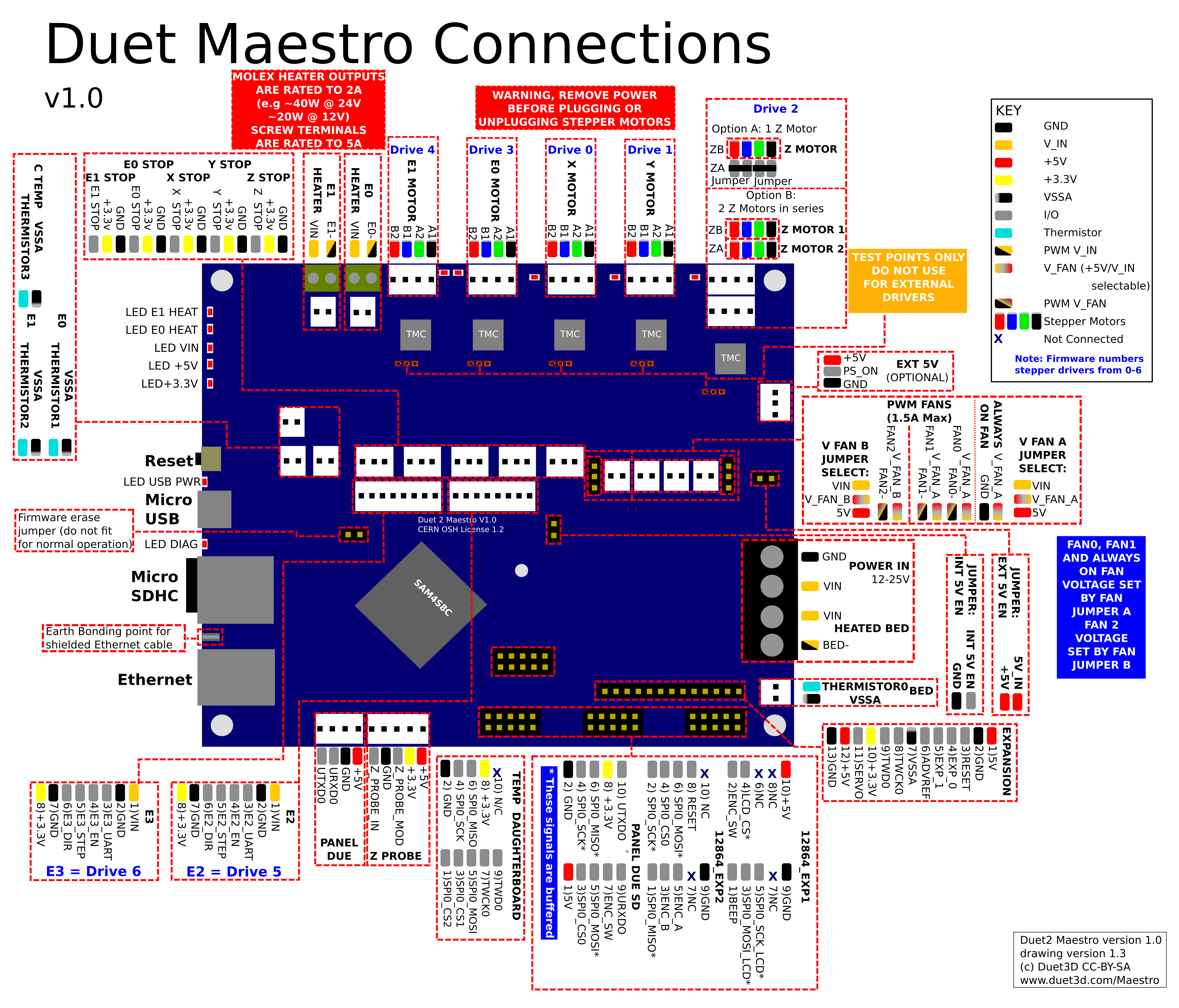
¶ Wiring diagram
There is an SVG version of this image available on Github.
Caution! If you are used to wiring other members of the Duet series, be aware that the VIN + and - terminals on the barrier strip of the Maestro are the opposite way round compared to Duets that use a 2-way screw terminal block to connect VIN.
¶ Description of connections
To do
¶ LED indications
To do
¶ Pin names
| Pin label on PCB/wiring diagram | RRF 3 pin name(s) | Notes |
|---|---|---|
| Heater outputs | ||
| BED HEATER | bedheat | Default H0, but you need to create Heater 0 to use it |
| E0 HEAT | e0heat | |
| E1 HEAT | e1heat | |
| Temperature inputs | ||
| BED TEMP | bedtemp | |
| E0 TEMP | e0temp | |
| E1 TEMP | e1temp | |
| C TEMP | ctemp | |
| Fan outputs | ||
| FAN0 | fan0 | |
| FAN1 | fan1 | |
| FAN2 | fan2 | |
| Endstop inputs | ||
| X STOP | xstop | |
| Y STOP | ystop | |
| Z STOP | zstop | |
| E0 STOP | e0stop | |
| E1 STOP | e1stop | |
| Miscellaneous | ||
| Z_PROBE_IN | zprobe.in | this can be used with smarteffector |
| Z_PROBE_MOD | zprobe.mod, servo | |
| PS_ON | pson | |
| EXP_0 | exp.pa21 | Expansion header (Pin 4) |
| EXP_1 | exp.pa22 | Expansion header (Pin 5) |
| TWD0 | exp.pa3 | Expansion header (Pin 9) and Temp DB header (Pin 9) |
| TWCK0 | exp.pa4 | Expansion header (Pin 8) and Temp DB header (Pin 7) |
| SPI CS | ||
| SPI0_CS1 | spi.cs1 | Temp DB header (Pin 3) |
| SPI0_CS2 | spi.cs2 | Temp DB header (Pin 1) |
¶ Input/output
To see where these pins are, see the Wiring diagram section above.
| Pin name (RRF 3.x) | Logical pin (RRF 2.x) | Location/PCB label | PWM capable? | Servo capable? | Notes |
|---|---|---|---|---|---|
| bedheat, e[0-1]heat | 0-2 | Heater connectors | yes | no | Heaters 0-2 on Duet mainboard |
| fan[0-2] | 20-22 | Fan connectors | yes | no | Fans 0-2 on Duet mainboard |
| [x,y,z,e0,e1]stop | 40-44 | Endstop connectors | no | no | Input only. Endstops on Duet mainboard |
| spi.cs1 | - | Temp DB, pin 3 | no | no | |
| spi.cs2 | - | Temp DB, pin 1 | no | no | |
| exp.pa21 | 60 | Expansion header EXP0 (pin 4) | no | no | Signal name: PA21/RXD1/AD8 |
| exp.pa22 | 61 | Expansion header EXP1 (pin 5) | no | no | Signal name: PA22/TXD1/AD9 |
| exp.pa3 | 62 | Expansion header TWD0 (pin 9) | no | no | Signal name: PA3/TWD |
| exp.pa4 | 63 | Expansion header TWCK0 (pin 8) | no | no | Signal name: PA4/TWC |
| zprobe.in | - | Z PROBE header Z_PROBE_IN (pin 1) | no | no | |
| zprobe.mod, servo | 64 | Z PROBE header MOD (pin 3), SERVO on expansion header (pin 11) | yes | yes | Shared pin. Signal name: Z_PROBE_MOD |
| pson | - | EXT 5V PS_ON | no | no |
Notes:
- Logical pin numbers for RRF 2.x are not the physical pin numbers on the expansion header, or the internal pin numbering within the firmware.
- The Z_PROB_MOD pin (pin 64) is driven automatically when some Z probe modes are selected.
- RRF 2.x - Disable a heater using M307 H# A-1 C-1 D-1 to make the pin available, where # is the heater number, and make sure that no tool is configured to use that heater.
- RRF 2.x - Disable a fan using M106 P# I-1 to make the pin available, where # is the fan number.
¶ Power distribution
The Duet 2 Maestro runs on two basic power circuits. The digital electronics are supplied by a 5V circuit, which is internally converted down to the 3.3V levels that drive the MCU. This circuit also drives all the LEDs and sensors, and can be configured to feed the fans. The high-power devices, specifically the stepper motors and the heaters, are powered by a higher voltage, typically 12 or 24 V. This 12/24V circuit can be switched on and off through the PS_ON pin, if the power supply supports this (it may be a good idea to add such support through a relay, for safety reasons, if it doesn't) without interfering with the MCU at all.
See also:
- Mounting and Cooling sections above
- Power Wiring
¶ Electronics power consumption
When on external 5V power with no connected devices drawing power from the 3.3V or 5V supplies, both the Duet 2 Maestro draws about 200mA average from the 5V supply with the network interface enabled.
¶ Connectivity
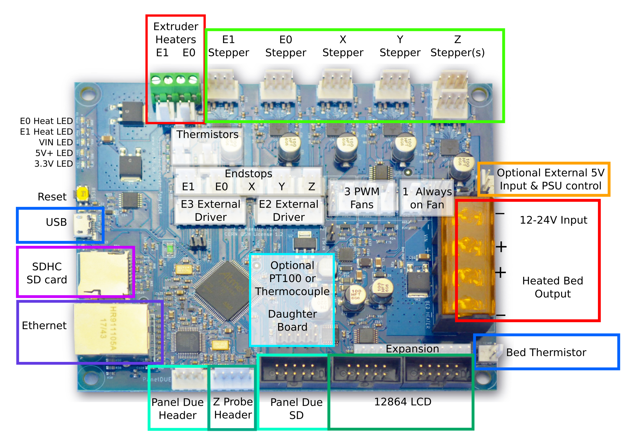
The board supports connection to a computer over USB, using any standard 3D printer host control program. The primary way to control the Maestro is with a web interface controlled through the network connected to the Ethernet port. Although they have removable on-board SD cards, the network interfaces provide fast enough file transfer that it is generally preferable never to remove the on-board SD card.
The Duet 2 Maestro also support the PanelDue colour touchscreen. Connectors for a 12864-type mono graphics display and rotary encoder are also provided.
See also:
¶ Motion
The Duet 2 Maestro can drive 5 independent stepper motors. It uses Trinamic TMC2224 stepper drivers, which in addition to the standard step/direction/enable interface provide additional functionality (for example digital current selection and interpolation between microsteps) through SPI. If users wish to use different drivers (for example supporting higher currents) then 2 additional channels of step/direction/enable/uart pins are available on the E2 and E3 external driver headers. With the onboard stepper drivers, it is possible to connect multiple motors in series; a connector is provided to make this convenient for the Z axis.
The Duet 2 Maestro provides connectors for one endstop for each axis; these can be simple microswitches (normally open or normally closed) or they can be more complicated boards (for example optical switches). 3.3V endstop power is provided and the inputs will tolerate up to 30V. Any of these endstop pins can also be configured to trigger user-defined actions, for example as a filament-out sensor or emergency-stop button.
The Duet 2 Maestro also provides a connector specifically for a Z probe. This supports simple switches, sensors producing analog outputs at 3.3 V levels, sensors providing analog outputs that require an on/off modulation signal, and sensors providing digital outputs at up to 30V.
See also:
- Connecting stepper motors
- Connecting endstop switches
- Connecting an Emergency Stop
- Connecting and configuring filament-out sensors
(NB these are not Maestro specific)
¶ Heating
The Duet 2 Maestro supports power distribution to three heaters: a heated bed (assumed to be the highest current draw with a maximum of 18A to be determined by thermal testing) and two extruder heaters (limited to 6A each). These are fed from the 12/24V circuit, but the PWM switching is carried out by MOSFETs on the ground, so if necessary they can be run off different voltages. Very high power bed heaters should be supplied independently and switched with a SSR on the expansion header.
Alongside each heater there is a temperature sensor input suitable for a thermistor or direct connection of a PT1000 sensor. Built-in ADC calibration and precision reference resistors provide accurate readings when using PT1000 sensors. Other types of temperature sensor including PT100 and thermocouple sensors can be connected using daughter boards.
There is a 4th thermistor/PT1000 temperature input channel for use with a chamber heater or for sensing enclosure or ambient temperature.
The Duet 2 Maestro also provides connectors for several fans, one always-on and 3 PWM-controlled. These can be supplied with 12/24V or with 5V, or (since again the switching is by MOSFETs on the ground line) if necessary from user-supplied power inputs.
See also:
- Connecting thermistors or PT1000 temperature sensors
- Connecting thermocouples
- Connecting PT100 temperature sensors
- Connecting a bed heater
- Connecting and configuring a chamber heater
- Connecting extruder heaters
- Connecting and configuring fans
(NB these are not Maestro specific)
¶ Expansion
The Duet 2 Maestro boards is not as expandable as the other Duet boards, however limited expansion is available. See the wiring diagram above for the expansion connector pinout.
There is also a Dual Stepper Driver Expansion Module that provides two extra TMC2224 stepper drivers.

