¶ Features
The Duet 3 Expansion 3HC supports the following:
¶ Hardware specification
| Processor | Atmel ATSAME51N |
| Prosessor features | 32-bit, 120MHz ARM Cortex-M4F, 512Kb flash, 384Kb RAM and many peripherals |
| Networking/Comms | CAN-FD BUS for connection to the Duet 3 Mainboard |
| On-board stepper drivers | 3 x TMC2160 |
| Stepper driver features | Up to 6.3A peak current, microstep interpolation from any setting to x256, stall detection, stealthChop2 |
| High current outputs | 3 x 6A each |
| Thermistor/PT1000 inputs | 3 x inputs, optimised for 100K thermistors and PT1000 sensors |
| Medium current outputs | 6 x PWM-controlled outputs, of which 3 support tacho input. Voltage selectable between VIN / 12V / external power, in 2 banks. One VIN-voltage, always-on output. |
| Inputs/Outputs | 6 x on-board I/O connectors for endstop, filament monitor, Z-probe or hobby servo connection. Inputs are 30V-tolerant. |
| PT100 and thermocouple daughterboard support | Supports 2 x daughterboards (4 channels) on board. |
| Power monitoring | VIN and 12V voltage reporting |
¶ Operating limits
| Stepper drivers | Up to 6.3A peak current |
| High current outputs | OUT0/1/2 up to 6A each |
| Input power voltage | Version 1.01 and earlier: 12V to 32V. Version 1.02: 12V to 48V |
| Inputs/Outputs | Inputs are 30V-tolerant |
| Input connector rated current | 25A maximum, or fused limit (whichever is lower) |
| Fuses | 10A for V_Fused. |
| 12V current limit | 800ma (total for out3-8 ports, when 12V selected) |
| 5V and 3.3V current limit | 800mA total on 5V and 3.3V, of which no more than 500mA from 3.3V. |
| Maximum ambient temperature | 70°C |
¶ Firmware notes
- Compatible RepRapFirmware versions: RRF 3.x
- Firmware limitations: See Duet 3 with CAN expansion firmware configuration limitations.
¶ Open source
- The Duet3 3HC is Open Hardware, see our license here.
- All hardware source files are available on Github.
- The Duet hardware and RepRapFirmware are built with Open tools: designed in KiCad and Eclipse using open tools means the barrier to getting involved is as low as possible.
¶ Physical properties
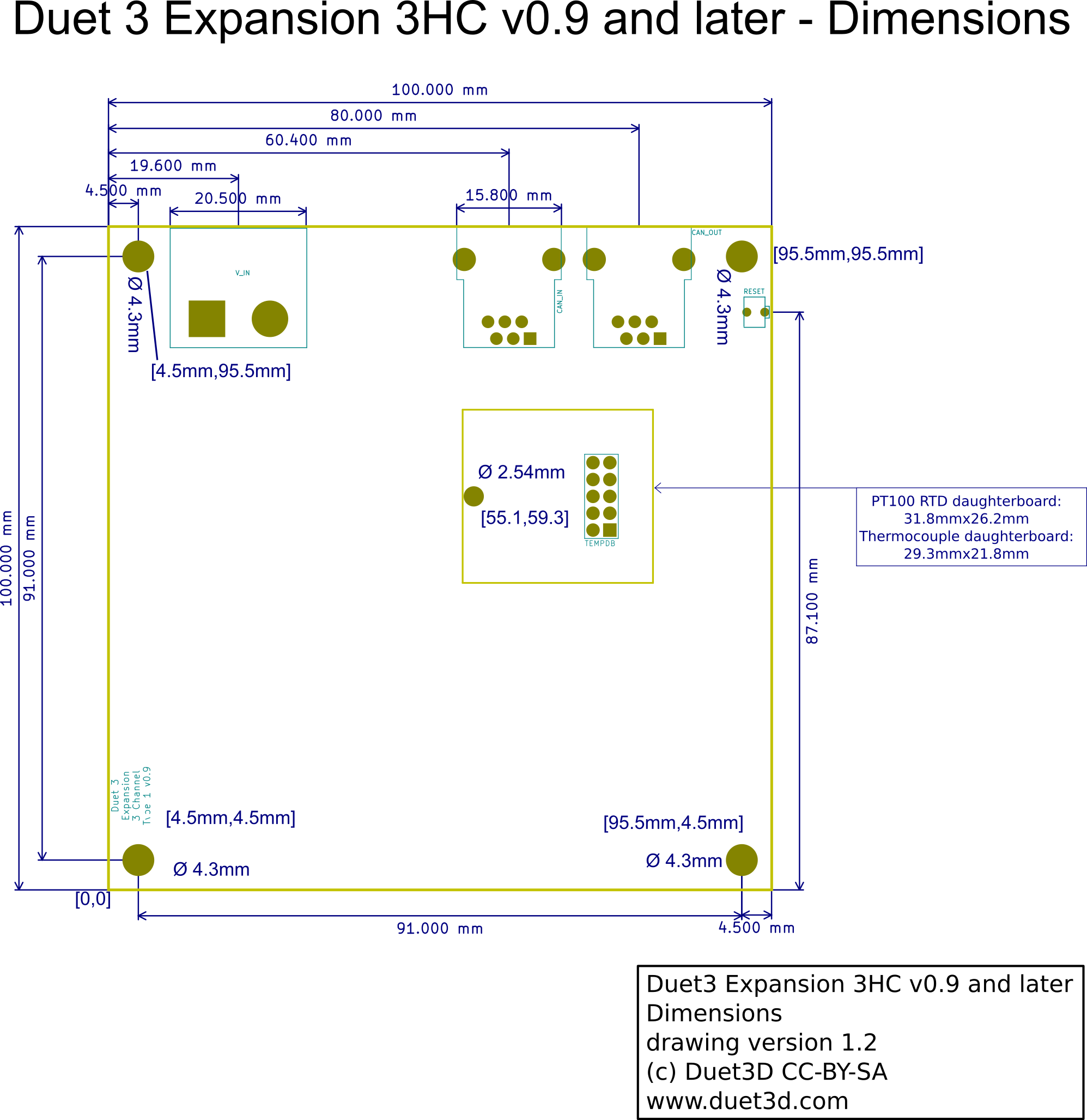
¶ Dimensions
Note for v1.02, the large 60V capacitors on the board are now slightly higher than previous versions, they are now the same height as the fuse in the fuse holder.
¶ Thermal tests
DC42 conducted thermal tests on the drivers running at 4.45A RMS (6.3A Peak) per phase:
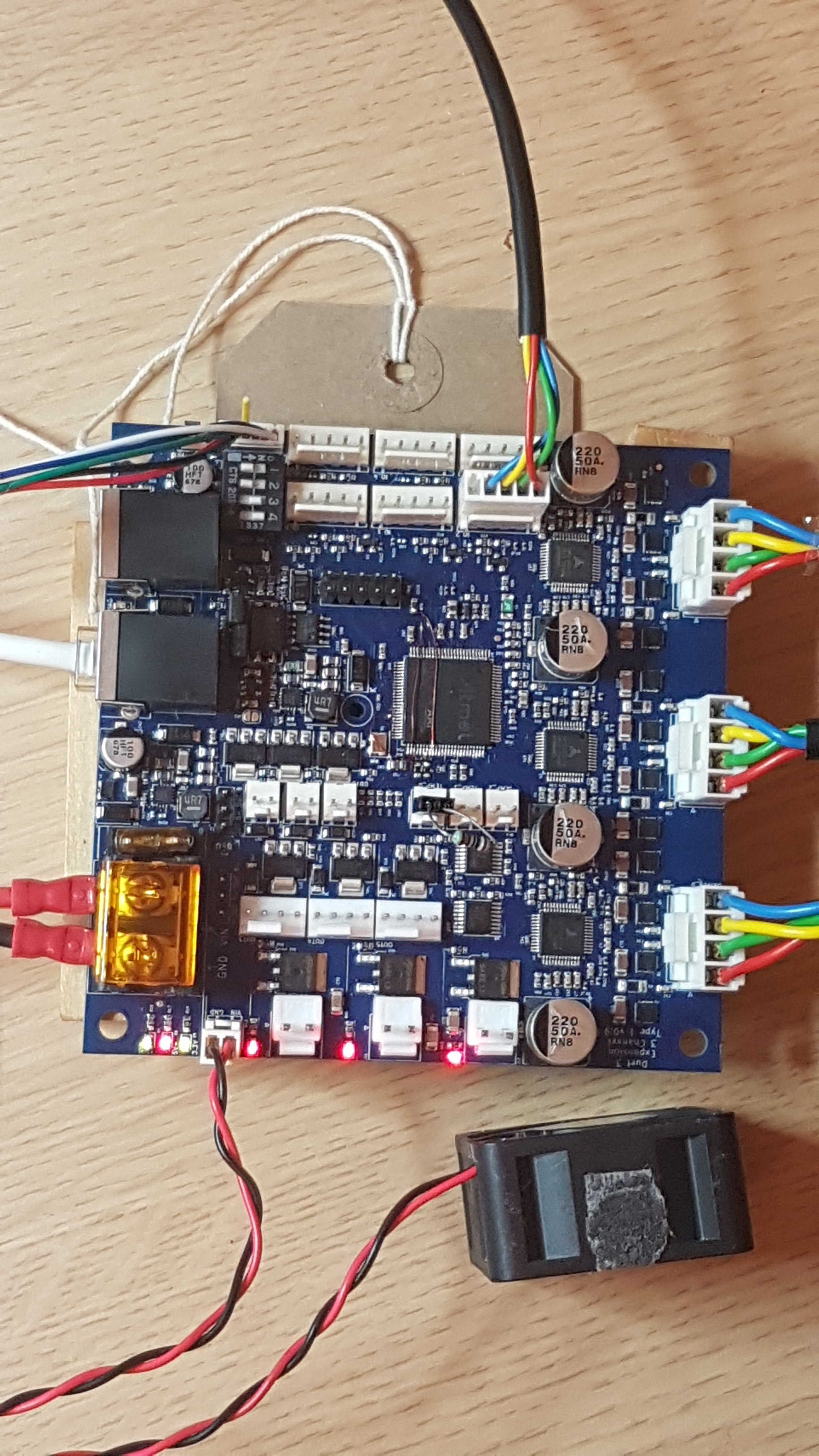
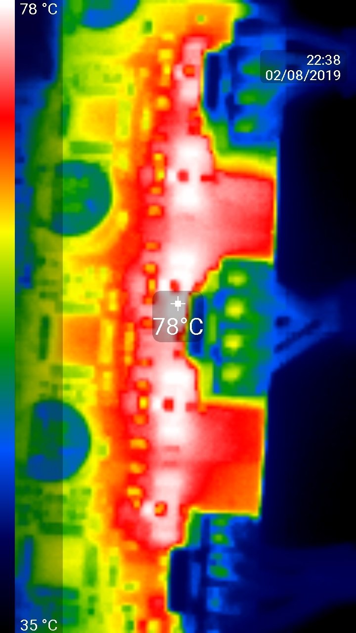
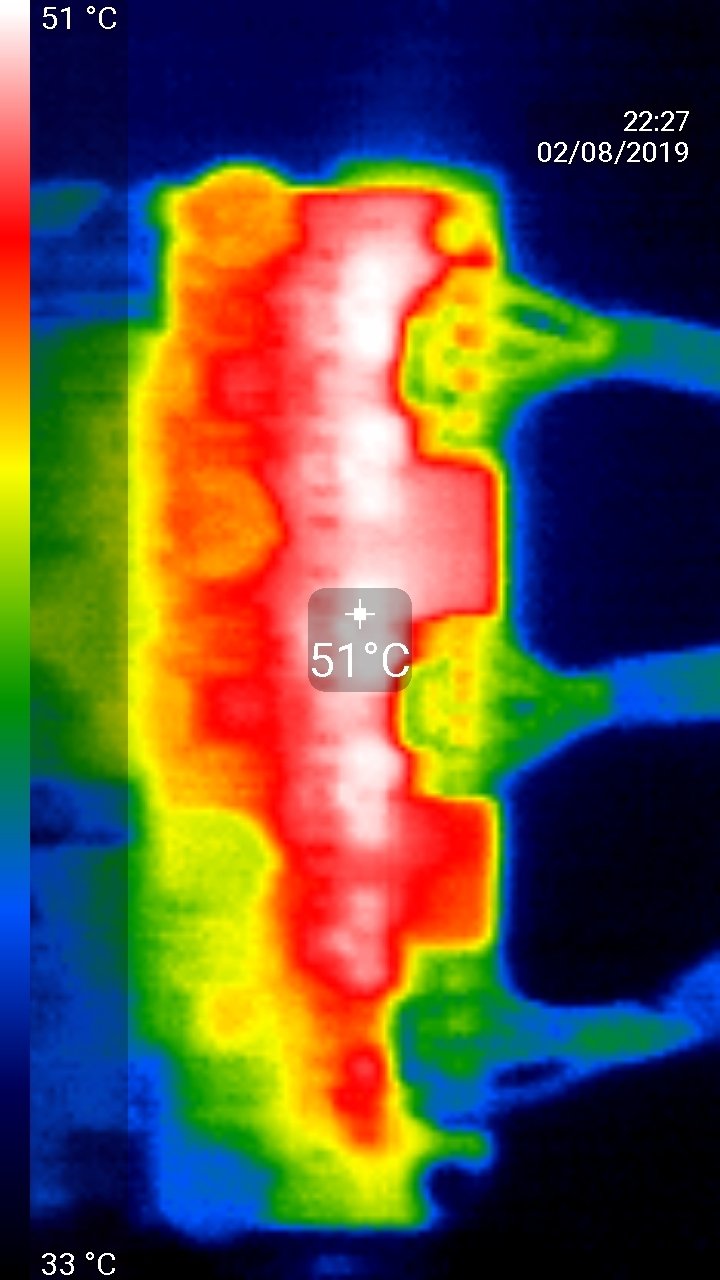
First image: Test setup.
Second image: FLIR image after 10 minutes, with no fan cooling, and the reported MCU temperature was 62.4C.
Third image: Adding a quiet 40x20mm Sunon fan brings the temperatures down nicely; the reported MCU temperature came down to 43C. Ambient temperature during these tests was 27C.
¶ 3D Model
Duet 3 Expansion 3HC STEP File on github
¶ Physical connections
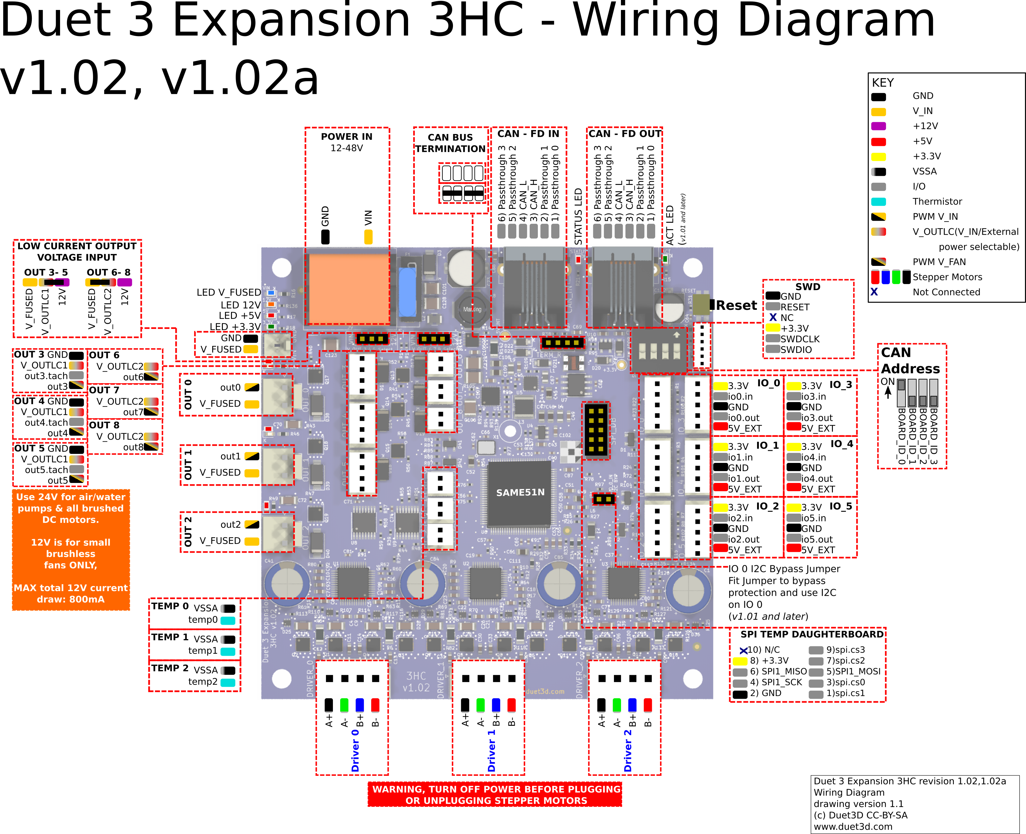
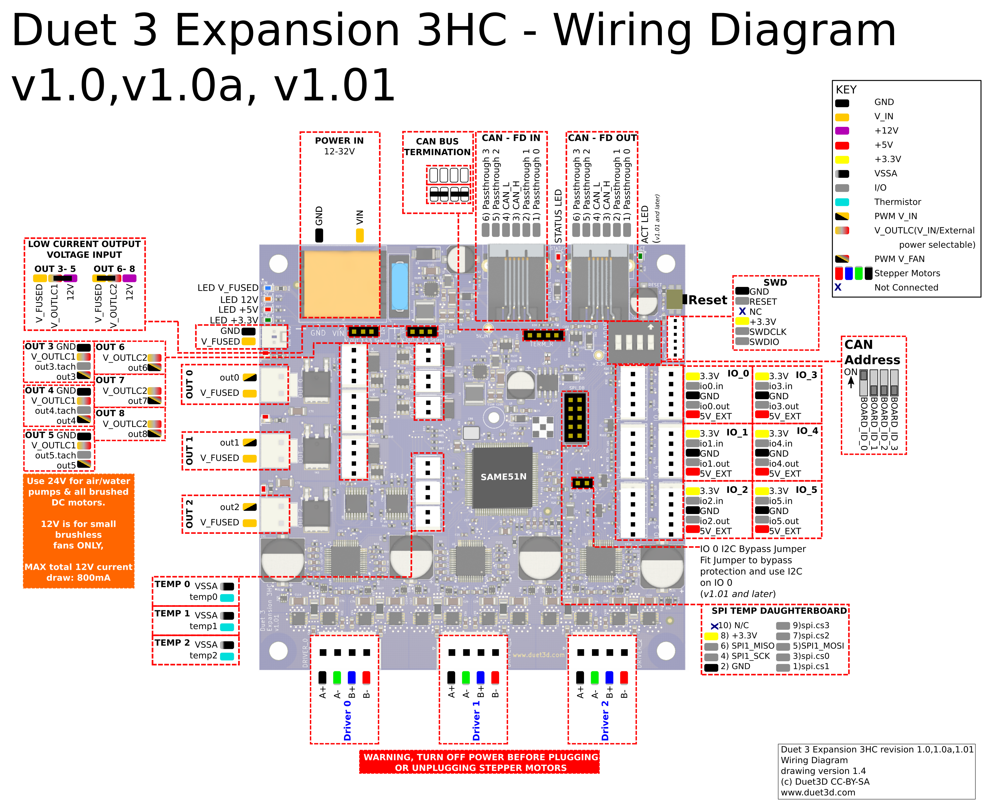
¶ Wiring diagram
v0.9 prototype wiring is the same as version 1.0 wiring.
¶ Wiring Notes
- JST VH connectors: The 4 wire motor and OUT_0 thru OUT_2 are JST VH series connectors. They require a minimum of 22AWG wire (20AWG or 0.5mm2 recommended). Most NEMA17 size stepper motor wire will will not be thick enough. You will need a suitable crimping tool for the crimp pins, for example Engineer PA21 (use the 2.2mm jaw opening to crimp the bare wire and the 2.5mm on to crimp the insulation). Alternatively you can solder the wire to the crimp pin.
¶ Description of Connections
Duet 3 Expansion 3HC provides the following connectors:
| Header | Label | Function |
|---|---|---|
| 1 x 2-way barrier strip | VIN, GND | Two pins for main VIN and GND. VIN power is fused at 10A, individual outputs from the board could add up to >10A (e.g. OUT_0, OUT_1 and OUT_2 are each rated to 6A max) however the total board current should not exceed 10A. |
| 1 x 2-pin KK header | GND V_FUSED | This is for powering an always-on fan or similar. |
| 3 x 2-pin JST VH | OUT_0 OUT_1 OUT_2 | Intended for high current output, eg extruder heaters or fans. Maximum recommended current 6A each. Flyback diodes are built-in to these outputs. (see note on JST VH connectors below) |
| 3 x 4-pin KK headers with offset spigot | OUT_3 OUT_4 OUT_5 | These are intended for PWM-controllable fans although they can be used for other purposes. Maximum recommended current 2.5A each. The connector fits a standard PC-type 4-pin PWM fan. Alternatively, a 2-pin fan may be connected between the V_OUTLC1 pin (+ve) and the OUT_[n]_NEG pin (-ve). |
| Note: OUT_3, OUT_4 and OUT_5 are protected by a flyback diode connected to V_OUT_LC_1. Do not mix loads connected to V_OUT_LC_1 with the jumper set to 12V and loads connected to V_FUSED on the same bank. | ||
| 1 x 3-pin KK header | OUT_3,4,5 Select V | The positive supply to the OUT_3, OUT_4, and OUT_5 connectors is the centre pin of the 3-pin jumper block. A jumper selects between powering them from the fused VIN supply or the internal 12V regulator. Alternatively you can connect a 3-terminal buck regulator to the 3-pin jumper block to supply the required voltage to the centre pin. |
| Max 12V current :The two banks of Low Current outputs (OUT_3-5, OUT_6-8) can be separately selected to be powered by either VIN or internal 12V. Total 12V fan current draw must not exceed 800mA. | ||
| 3 x 2-pin KK headers | OUT_6 OUT_7 OUT_8 | These are intended for fans. Maximum recommended current 2.5A each. Flyback diodes are built-in to these outputs. |
| Note: OUT_6, OUT_7 and OUT_8 are protected by a flyback diode connected to V_OUT_LC_2. Do not mix loads connected to V_OUT_LC_1 with the jumper set to 12V and loads connected to V_FUSED on the same bank. | ||
| 1 x 3-pin KK header | OUT_6,7,8 Select V | The positive supply to these connectors is the centre pin of the 3-pin jumper block. A jumper selects between powering them from the fused VIN supply or the internal 12V regulator. |
| Max 12V current :The two banks of Low Current outputs (OUT3-5, OUT6-8) can be separately selected to be powered by either VIN or internal 12V. Total 12V fan current draw must not exceed 800mA. | ||
| 3 x 2-pin KK headers | TEMP_0 TEMP_1 TEMP_2 | Connections for thermistor or PT1000 sensors. |
| 1 x 2x5 header | This is for connecting PT100 and thermocouple interface boards (the same boards that the Duet 2 series uses). | |
| 3 x 4-pin JST VH | DRIVER_0 DRIVER_1 DRIVER_2 | Stepper motor connections. (see note on JST VH connectors) |
| 1 x 2x5 header | SPI_1 / TEMPDB | This is for connecting PT100 and thermocouple interface boards. |
| 6 x 5-pin KK headers | IO_0 IO_1 IO_2 IO_3 IO_4 IO_5 | These are for endstop switches, Z probes, filament monitors, servos, and other low-voltage I/O functions. Each connector provides both 3.3V and 5V power. The inputs will tolerate up to 30V. The outputs are 3.3V signals levels with 470R series resistors. |
| Caution! Check the pinout of these using the wiring diagram linked above before connecting anything to them. | ||
| 1 x 6-pin SWD connector | SWD | This is for firmware debugging and also provides a backup mechanism to program firmware. |
| 1 x 4-way DIP switch | CAN ADDR | Used for setting the CAN address. See CAN section below. |
| Reset | Single push to reset the board. | |
| 2 x RJ11 CAN connectors | CAN_IN CAN_OUT | RJ11 CAN connectors. See CAN section below. |
| 1 x 4-pin jumper header | TERM_R | CAN bus termination. See CAN section below. |
¶ LED indications
LEDs are provided to indicate the following:
| Label | Colour | Function |
|---|---|---|
| V_FUSED | Blue | Indicates presence of fused VIN power |
| 12V+ | Amber | Indicates presence of 12V power from on-board regulator |
| 5V+ | Red | Indicates presence of 5V power from on-board regulator |
| 3.3V+ | Green | Indicates presence of 3.3V power from on-board regulator |
| OUT_0 | Red | Next to the OUT 0 connector, indicates when on |
| OUT_1 | Red | Next to the OUT 1 connector, indicates when on |
| OUT_2 | Red | Next to the OUT 2 connector, indicates when on |
| DIAG | Red | Diagnostic LED. See description below |
Diagnostic LED: when the expansion board starts up this LED will blink rapidly. If the expansion board is connected to a main board running compatible firmware, the LED on the expansion board will switch to blinking synchronously with the main board LED once time sync has been established across the CAN bus.
¶ Pin names
For more information on pin names, see Pin Names.
RepRapFirmware 3 uses pin names for user-accessible pins, rather than pin numbers, to communicate with individual pins on the PCB. In RRF 3 no user-accessible pins are defined at startup by default. Pins can be defined for use by a number of gcode commands, eg M574, M558, M950.
The Duet 3 series uses the pin name format "expansion-board-address.pin-name" to identify pins on expansion board, where expansion-board-address is the numeric CAN address of the board. A pin name that does not start with a sequence of decimal digits followed by a period, or that starts with "0." refers to a pin on the Duet 3 Mainboard.
| Pin location | RRF3 Pin name | Notes |
|---|---|---|
| Heater outputs | ||
| OUT_0 | out0 | VIN. Maximum recommended current 6A each. |
| OUT_1 | out1 | |
| OUT_2 | out2 | |
| Outputs (4-pin) | ||
| OUT_3 | out3 | Fans, pumps. 2.5A limit per pin on VIN, 800mA limit total on internal 12V |
| out3.tach | ||
| OUT_4 | out4 | |
| out4.tach | ||
| OUT_5 | out5 | |
| out5.tach | ||
| Outputs (2-pin) | ||
| OUT_6 | out6 | |
| OUT_7 | out7 | |
| OUT_8 | out8 | |
| Temperature inputs | ||
| TEMP_0 | temp0 | |
| TEMP_1 | temp1 | |
| TEMP_2 | temp2 | |
| Inputs/Ouputs | ||
| IO_0 | io0.in | Endstops, Z probes, filament monitors etc |
| io0.out | ||
| IO_1 | io1.in | |
| io1.out | ||
| IO_2 | io2.in | |
| io2.out | ||
| IO_3 | io3.in | |
| io3.out | ||
| IO_4 | io4.in | |
| io4.out | ||
| IO_5 | io5.in | |
| io5.out | ||
| SPI CS | ||
| SPIO | spi.cs0 | Thermocouple and/or PT100 daughterboard |
| spi.cs1 | ||
| spi.cs2 | ||
| spi.cs3 | ||
¶ Input/Output
There are 6 IO headers on board. Each has an input and output along with 3.3V, 5V and Gnd supplied. This enables them to support a wide range of endstops, probes, filament monitors and future low bandwidth devices.
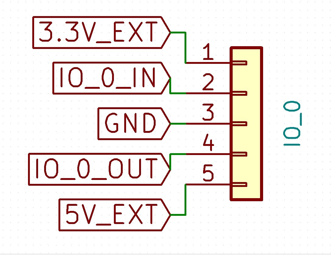
RepRapFirmware 3 can be configured to map these ports to the appropriate functions as required.
Except as noted in the table below, an IO_x_IN pin can always be used to provide a digital input (e.g. for endstop inputs or filament monitors), and an IO_x_OUT pin can always be used to provide a digital output. On the version 0.6 and 1.0 boards the individual IO_x connectors have the following additional capabilities:
| IO # | UART/I2C? | Analog in? | PWM out? | Notes |
|---|---|---|---|---|
| 0 | yes1 | yes | no | Can be used with I2C from v1.01 onwards 2 |
| 1 | yes1 | yes | yes | |
| 2 | yes1 | yes | no | |
| 3 | no | no | no | |
| 4 | no | no | yes | |
| 5 | no | yes | no |
1 RepRapFirmware does not currently support UART or I2C on Duet 3 expansion/tool boards.
2 To use IO 0 with I2C the protection bypass resistor must be fitted to bypass the 10K series resistor. If this is fitted then IO0.in is no longer protected sufficiently against over voltage/over current. Note that RepRapFirmware does not currently support I2C on Duet 3 boards.
¶ Power wiring
VIN in the range 12V-48V (12V-32V v1.01 and earlier) must be provided to the Duet expansion board. The board produces onboard 12V, 5V and 3.3V, from VIN (12V will not be produced if only 12V is provided as VIN).
These voltages are divided for internal and external use, with external 3.3V and 5V going to IO and other headers, and external 12V if provided to the low current fan voltage selection pins.
Max 12V current: The two banks of Low Current outputs (OUT3-5, OUT6-8) can be separately selected to be powered by either VIN or internal 12V. Total 12V fan current draw must not exceed 800mA.
Max 5V and 3.3V current: Up to 800mA from 3.3V and 5V combined, of which no more than 500mA from 3.3V.
If you use a relay to control VIN power to the board, ie the power supply is already switched on, and a relay is used to turn on power to the board, you should use an inrush current limiter wired in series with VIN. See the section on Inrush current here.
OUT ports on the mainboard should NOT be used to switch power to expansion or tool boards directly. See the note at the end of the 'inrush current' section at the link above.
¶ CAN
See also CAN connection basics.
¶ Connection
Two RJ11 connectors labeled CAN IN and CAN OUT. In fact it doesn't matter which you use for the cable from the main board and which you use for the cable to the next expansion board, because they are wired in parallel.
The DIAG LED between the two CAN connectors indicates CAN bus state. When the expansion board starts up this LED will blink rapidly. If the expansion board is connected to a main board running compatible firmware, the LED on the expansion board will switch to blinking synchronously with the main board LED once time sync has been established across the CAN bus.
¶ Termination
Just behind the RJ11 connectors is a 4-pin terminal block. On the last board in the CAN chain only (the one with a cable in only one of the RJ11 connectors), two jumpers must be fitted in that block to terminate the CAN bus. Jumpers must not be fitted in expansion boards that are not at the end of the CAN bus.
¶ Address
The Duet 3 Expansion 3HC has a 4-bank DIP switch to set the address. The CAN address is set by the switches as follows:
| 1 | 2 | 3 | 4 | Address |
|---|---|---|---|---|
| off | off | off | off | 126 (board requests firmware on startup) |
| on | off | off | off | 1 |
| off | on | off | off | 2 |
| on | on | off | off | 3 |
| off | off | on | off | 4 |
| on | off | on | off | 5 |
| off | on | on | off | 6 |
| on | on | on | off | 7 |
| off | off | off | on | 8 |
| on | off | off | on | 9 |
| off | on | off | on | 10 |
| on | on | off | on | 11 |
| off | off | on | on | 12 |
| on | off | on | on | 13 |
| off | on | on | on | 14 |
| on | on | on | on | 15 |
¶ Commissioning
¶ Startup Time
It is recommended to add the following to config.g, before any commands that reference any CAN bus connected expansion boards
G4 S2 ; wait for expansion boards to start
¶ Testing communication
Check that you can communicate with the Duet 3 Expansion 3HC board, by sending:
M115 B1
If that fails, check the CAN address set by the 4-bank DIP switch. Check that the DIAG LED is blinking synchronously with the main board LED, which shows if synchronisation has been established on the CAN bus.
¶ Update the bootloader
Duet 3 expansion boards and tool boards have a bootstrap loader written to the start of flash so that they can load firmware from the main board via CAN. This bootloader may occasionally need to be updated in order to support new features. See Updating the bootloader on Duet 3 expansion and tool boards.
¶ Updating the firmware
The 3HC board will be shipped with firmware loaded during production. You can check the version loaded by sending
M115 B1
(or B## where ## is the new CAN address of the board if you have changed it already)
To update the firmware get the latest version from the RepRapFirmware github. It is recommended to upgrade all the firmware in your Duet 3 system together so that the versions do not get out of sync.
Send M997 B## to carry out a firmware update, the bootloader will request the Duet3Firmware_EXP3HC.bin from the Duet 3 main board, it needs to be in the /firmware folder (/sys folder for versions of RRF before 3.3).
Once the update is complete restart the mainboard and 3HC, then send M115 B## (where B## is the address set with the dip switches) to check the firmware is updated.
¶ Forcing a firmware update
If the 3HC is unresponsive, or the firmware update is not working, set all the dip switches to "off", then reset the 3HC. This will force the 3HC bootloader to request a firmware update over CAN when it starts up. Once the firmware update had completed and the sync light is flashing in time with the Duet 3 mainboard then set the dip switches back to the address being used for this board and reset the Duet 3 mainboard and the 3HC.
Ensure the 3HC firmware is in the /firmware directory (/sys on RRF versions earlier than 3.3)
Ensure you have can communication (the status light is flashing in sync with the Duet 3 mainboard)
¶ Revision History
- Changed stepper driver MOSFETS to ones used on 6HC due to part availability - no functional change.
- Changed 3.3V external regulator to one used on other Duet 3 boards due to part availability - no functional change.
- Other minor component changes to align with other Duet 3 boards - no functional change.
- Improved input protection on Tacho/Io and temperature sensing inputs
- Changed MOSFETS due to part availability - no functional change.
- Changed the voltage input and other components to support 48V operation.
- Added flyback diodes to the high current outputs
- Improved the noise performance of the CAN-FD connection
- Added protection diodes to tacho inputs
- The large 60V capacitors on the board are now slightly higher, they are now the same height as the fuse in the fuse holder.
- Added a green LED for CAN Activity.
- Add Programming pads so the SWD header does not need to be used for initial programming.
- Enlarged the VFUSED trace to the three high current outputs so its capable of handling 15A@40C rise.
- Added bypass jumper to IO_0_IN to bypass the 10K protection resistor to allow for I2C to be used on IO_0.
Note: RepRapFirmware does not currently support I2C on Duet 3 boards. - Many changes to components to work around supply chain issues that do not impact the functionality of the board.
- Improved thermistor circuit connections
- Change stepper driver output labelling to A+ A- B+ B- to match other Duet 3s
- Add an LED to indicate when +12V is present
- Rotate the DIP switch 180 degrees
- Changed CAN polarity so a cross over cable was not needed.
- Swap polarity of OUT0, OUT1 and OUT2 connectors, for consistency with the 2-pin Molex KK connectors
- improve stepper driver output circuits.
- initial prototype distributed.
Wiring is the same as version 1.0 wiring but the SPI daughterboard connector is not functional.
