¶ Introduction
The Duet 3 Mainboard 6XD is designed to allow interfacing with the most common external stepper and servo motor drivers using step and direction signals, with support for 6 external drivers. In addition it provides opto-isolated Input and Output connections for some of the GPIO functions to allow easier interfacing with PLC control systems.
Like the other Duet 3 mainboards it can be accessed directly over the network in stand alone mode (via the Ethernet port) or it has the option of using an SBC (Single Board Computer, e.g. Raspberry Pi) for control. Using the Duet 3 CAN-FD bus it is expandable with the range of Duet 3 expansion and tool boards.
¶ Features
¶ Hardware Specification
The main hardware features of the Duet 3 6XD are listed below.
| HARDWARE SPECIFICATION | |
|---|---|
| Processor | ATSAMV71Q20B. Alternatively the ATSAME70Q20B will be used. They are functionally equivalent in this design |
| Processor features | 32-bit, 300MHz ARM Cortex M7, 1Mb flash, 384Kb RAM, hardware floating point (double precision), DMA, 32Kb cache |
| Networking/Comms | 10BaseT/100BaseTX Ethernet, or via attached SBC; USB port; serial port; CAN-FD bus |
| External Driver Support | 6 ports with step/direction/enable outputs, and fault inputs. Signalling is 5V single ended. |
| High current outputs | 3 x 6A each |
| Medium current outputs | 6 x PWM-controlled outputs, of which 3 support tacho input. Voltage selectable between VIN / 12V / external power, in 2 individually-fused banks. 1 x VIN-voltage, always-on output. 1 x 12V, always-on output. |
| Thermistor/PT1000 inputs | 4 x inputs, optimised for 100K thermistors and PT1000 sensors |
| Inputs/Outputs | 9 x on-board I/O connectors for endstop, filament monitor, Z probe, hobby servo, or PanelDue connection. Inputs are 30V-tolerant. 4 of the 9 pairs of IO also have alternative opto-isolated connectors. |
| Power monitoring | VIN voltage monitoring allows for state save on power failure.12V regulator output voltage also monitored |
| SD card interface | On-board high speed (25Mbytes/sec) SD card socket. External SD card socket (e.g. on attached PanelDue) also supported. |
| EXPANSION | |
|---|---|
| Support for attached Raspberry Pi or other Single Board Computer (SBC) | Yes |
| External stepper driver support | 6 on board, further via CAN-FD bus |
| Stepper driver expansion | Via CAN-FD expansion boards |
| IO/Output/thermistor expansion | Via CAN-FD expansion boards |
| PT100 and thermocouple daughter board support | Supports 2 x daughterboards (4 channels) on board. Additional boards supported via CAN-FD-connected expansion boards. |
| Servo support | One output with 5V signal level for hobby servo, laser or VFD converter |
| LCD support | PanelDue, or via HDMI touch screen attached to the SBC. |
| LED strip support | Neopixel (max. 60 LEDs) or DotStar |
| RS485 Support | V1.02 or later, firmware support for MODBUS RTU from RRF 3.6.0 |
¶ Operating limits
| Input power voltage | 11V to 30V (14V-30V to use onboard 12V regulator) |
| Input connector rated current | 25A maximum, or fused limit (whichever is lower) |
| High current outputs | 3 x high current outputs up to 6A each, total high current heater limit fused at 15A |
| Medium current outputs | 6 x medium current outputs up to 1A each, each bank of medium current outputs fused at 2A (note when set to 12V there is a total 800mA limit) |
| External Driver Signal voltage | 5V nominal (min. 4.2V @ 20mA) |
| External Driver Signal current | 20mA maximum |
| Non opto isolated Inputs | Permanent 27K pullup resistor to +3.3V included. Input voltage limits: -1V to +30V. |
| Non opto isolated Outputs | 3.3V signal level, 470 ohm series resistor |
| Opto Isolated Inputs | 24V nominal, working range 12V to 50V. Reverse polarity protection included. Compatible with both PNP and NPN PLC outputs. |
| Opto Isolated Outputs | Max voltage 55V, max current 50mA |
| Driver Error inputs | Selectable 10K pullup resistor to +5V or 10K pull down to GND. Input voltage limits: -1V to +24V. |
| Fuses | 15A for V_FUSED, 3A for each bank of medium current outputs/ |
| 5V current limit | 2A total on 5V including any PanelDue or other display, and any endstops/Z probes that draw significant power, and any SBC powered by the Duet. |
| 3.3V current limit | No more than 300mA from 3.3V external. |
| 12V current limit | 800mA (only used for fan outputs OUT_3 thru OUT_8, when selected) |
| Maximum ambient temperature | 70°C |
¶ Firmware notes
- Duet 3 Mainboard 6XD is compatible with RepRapFirmware version 3.4.1 and later.
- For firmware update instructions:
- Standalone mode - Installing and updating firmware.
- SBC mode - SBC setup for Duet 3.
- There are some limits on firmware and hardware configuration. See:
¶ Open Source
- The schematic and BOM are available are available on Github.
- Both the Duet Web Control web interface and RepRapFirmware are Open Source Software with source files available and actively maintained, see Contributing to development for more information.
- The Duet hardware and RepRapFirmware are built with Open tools: designed in KiCad and Eclipse using open tools means the barrier to getting involved is as low as possible.
¶ Feature Comparison
See the Hardware overview page for a feature comparison table between different versions of the Duet.
¶ Physical properties
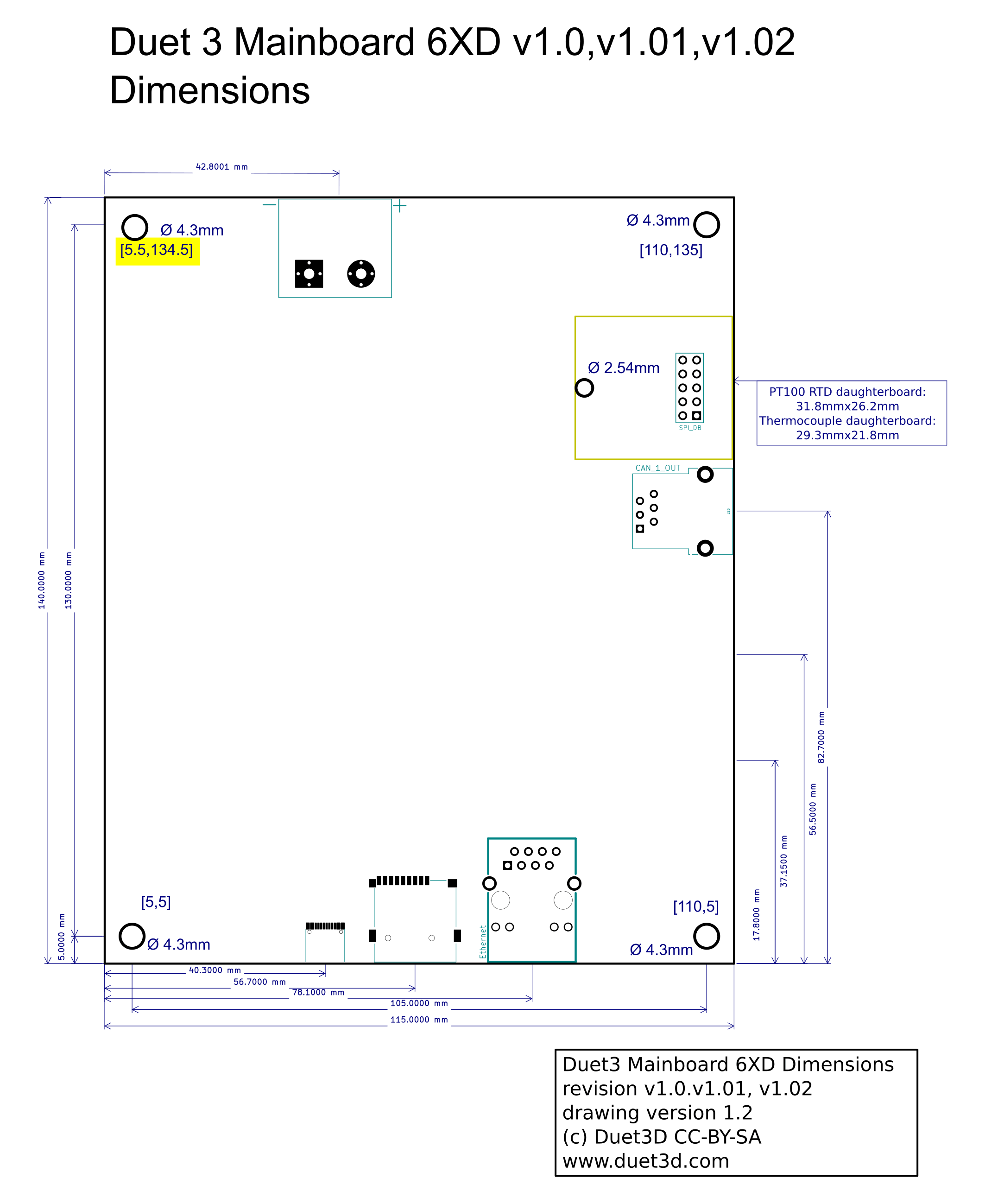
¶ Dimensions
¶ 3D Model
A STEP file is available on GitHub here.
¶ Mounting
The mounting holes are isolated and not plated through, they have a keep out area around the M4 clearance hole of an additional 2.2mm radius. Any metallic mounting solution should be kept inside this keep-out area.
The board should be mounted on standoffs, ensuring the back of the board cannot come into contact with a conductive surface.
¶ Cooling
In many applications passive cooling will be sufficient, especially if the board is mounted vertically in a well ventilated position. If active cooling is needed then a fan blowing across the back of the board will cool the high current MOSFET heat sinking and onboard power supply heatsinking.
The MOSFETs' heatsinks are connected to the PCB and the majority of the heat is dissipated via the PCB so heatsinks on the FETs or other ICs are largely ineffective.
¶ Physical connections
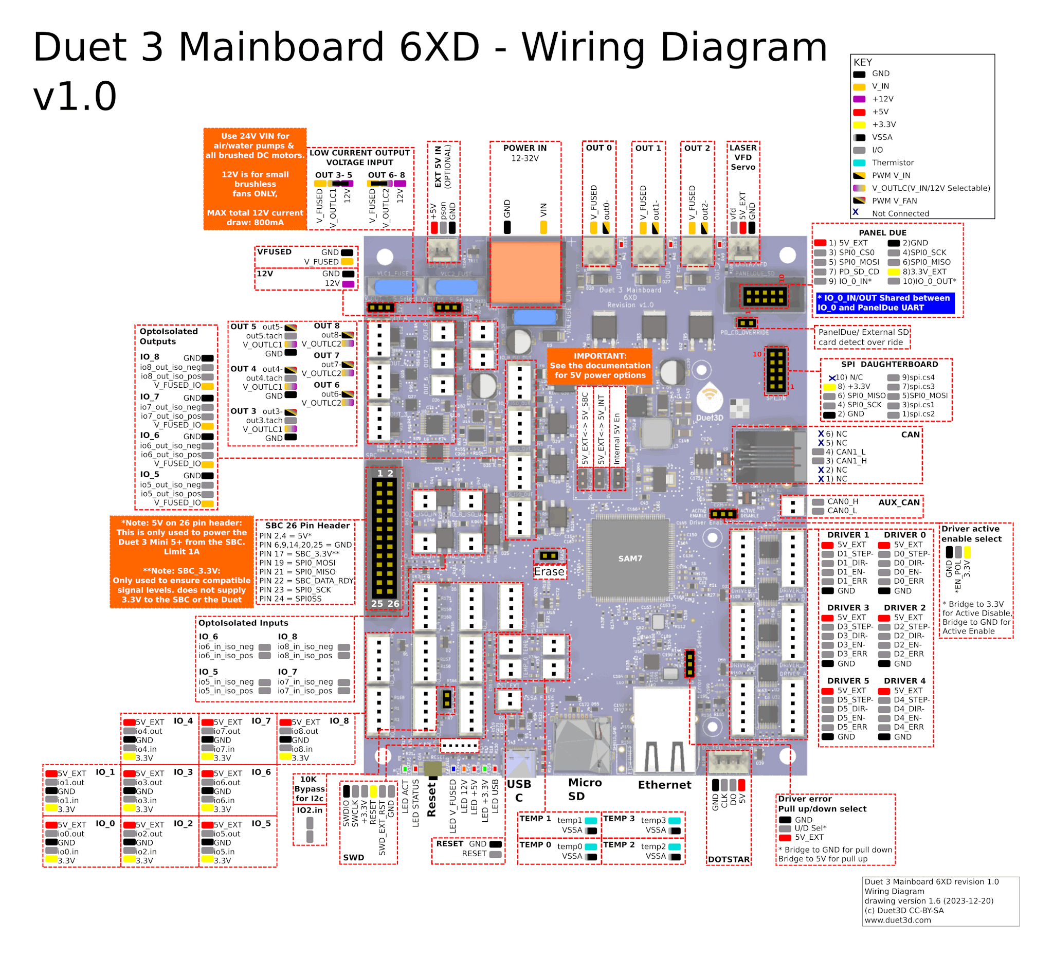
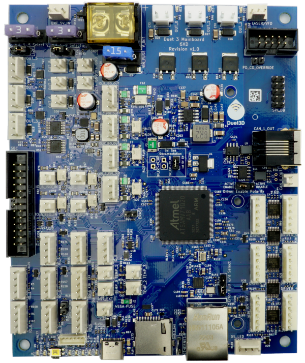
¶ Wiring diagram
Duet3 Mainboard 6XD prototype v0.1 Wiring Diagram
¶ Errata
in the v0.1 prototypes the Driver Active enable select options: "ACTIVE ENABLE" and "ACTIVE DISABLE" legends are the wrong way round on the board silk screen
¶ Description of Connections
| Duet 3 6XD Connectors and Jumpers | ||
|---|---|---|
| 1 x 2-way barrier strip | POWER IN, GND, VIN | Two pins for the main VIN and GND, protected by a 15A fuse. |
| 1 x 3-pin KK connector | EXT 5V | Open drain mosfet output for controlling an ATX-style power supply or a SSR. The +5V pin can also be used to provide external 5V power. A small amount of 5V power can be drawn from this pin (through an internal 220 ohm resistor), so that the control terminals of an SSR can be connected directly between the +5V and PS_ON pins. |
| 3 x 2-pin JST VH connectors | OUT_0, OUT_1, OUT_2 | Intended for extruder heaters or similar high current resistive loads. The out0, out1, out2 pins are PWM switched GND, the V_FUSED pins are fused input voltage. Flyback diodes are built-in to these outputs. Maximum current 6A each, 15A total |
| 3 x 4-pin KK connectors | OUT_3, OUT_4, OUT_5 | Intended for PWM-controllable fans or other medium current loads. The connector fits a standard PC-type 4-pin PWM fan. Alternatively, a 2-pin fan may be connected between the V_OUTLC1+ pin (+ve) and the OUT_n_NEG pin (-ve). |
| Note: OUT_3, OUT_4, OUT_5 are protected by a flyback diode to V_OUTLC1. This does not provide protection if driving these outputs from a higher voltage than V_OUTLC1. V_OUTLC1 is fused with a 3A fuse. | ||
| 1 x 3-pin Jumper | OUT_3-OUT5 Select V | The positive supply to the above connectors is the centre pin of the 3-pin jumper block. A jumper in the "left" position will power them from the fused VIN supply (max 2A each, 3A total). A jumper in the "right" position will power them from the onboard 12V regulator (subject to overall 12V supply current see note 1 below). |
| 3 x 2-pin KK connectors | OUT_6, OUT_7, OUT_8 | These are intended for PWM-controllable fans or other medium current loads. |
| Note: OUT_6, OUT_7, OUT_8 are protected by a flyback diode to V_OUTLC2. This does not provide protection if driving these outputs from a higher voltage than V_OUTLC2. V_OUTLC2 is fused with a 3A fuse. | ||
| 1 x 3-pin Jumper | OUT_6-OUT8 Select V | The positive supply to the above connectors is the centre pin of the 3-pin jumper block. A jumper in the "left" position will power them from the fused VIN supply (max 2A each, 3A total ). A jumper in the "right" position will power them from the onboard 12V regulator (subject to overall 12V supply current see note 1 below). |
| 1 x 2-pin KK connector | V+ GND | Always on V_FUSED supply, do not draw more than 2A from this connector |
| 1 x 2-pin KK connector | 12V GND | Always on 12V supply (see note 1 below) |
| 1 x 3-pin KK connector | LASER/VFD | 5V buffered output, along with 5V and ground supply (see note 2 below). Provides a 5V PWM signal to drive hobby servos, and PWM->analog controls for VFDs or Lasers. |
| 1 x 2x5 IDC connector | PanelDue_SD | Connects the PanelDue UART and shared SPI bus for external SD card. Powered from 5V supply (see note 2). |
| Note The PanelDue UART is shared with io0.in and io0.out pins on the IO_0 header. | ||
| 1 x 2-pin Jumper | PD_CD_OVERRIDE | v1.0 boards and later. Add a jumper to connect Card Detect on the PanelDue to ground, to handle PanelDue versions that don't support Card Detect. |
| 1 x RJ11 CAN connector | CAN_1_OUT | RJ11 connector for CAN1 (main CAN-FD bus). USE CAN1 for connecting Duet expansion boards, see CAN-FD bus expansion section below. Without modification, it must be at one end of the CAN bus, however the bus termination resistors can be disconnected with drillable/solder-able jumpers underneath the board |
| 1 x 2-pin KK connector | CAN_0_OUT | Secondary CAN-FD bus for future expansion. Use CAN1 for connecting expansion boards, see CAN-FD bus expansion section below. Bus termination resistors can be disconnected with drillable/solder-able jumpers underneath the board |
| 1 x 2x5 IDC connector | SPI_DB | For connecting up to two PT100 or thermocouple interface boards. |
| 6 x 6-pin KK connectors | DRIVER_0-DRIVER_5 | External stepper or servo motor driver connections. 5V, GND, single ended outputs for Step, Dir and Enable along with a fault input provided per driver. See "Connecting External Drivers" section below. |
| 1 x 3-pin Jumper | Driver Enable Polarity | A jumper in the "left" position is used for external drivers which are enabled when a voltage is applied to the enable connection (Active Enable). A jumper in the "right" position is used for external drivers which are disabled when a voltage is applied to the enable connection (Active Disable) (Note the v0.1 boards have the silkscreen reversed). |
| 1 x 3-pin Jumper | Error Pull u/d Select | A jumper in the "top"/Pull Down position applies a pull down resistor to the driver fault signals - an external driver must set the line high to indicate a fault. A jumper in the "bottom"/Pull Up position applies a pull up resistor to the driver fault signals - an external driver must set the line low to indicate a fault |
| 1 x 4-pin KK connector | DS_LED | This is to connect and power DotStar LED strips. |
| Caution! see note 2 below | ||
| Network | Ethernet | 1 x RJ45 100BaseT Port. non MDIX connect to an Ethernet switch, hub or MDIX enabled laptop port. If connecting to a non MDIX enabled port use a crossover cable. Orange LED on Ethernet port indicates Ethernet enabled, green LED indicates network activity |
| 1 x USB C | USB | USB 2.0 for initial firmware installation and USB power. Up to 1A max current allowed, do not power high current 5V loads through this USB port (e.g. SBC with screen or large strings of LEDs) |
| 4 x 2-pin KK connectors | TEMP_0,-TEMP_3 | Connections for thermistor or PT1000 sensors. |
| 9 x 5-pin KK connectors | IO_0-IO_8 | Duet 3 standard GPIO ports. These are for endstop switches, Z probes, filament monitors and other low-voltage I/O functions. Each connector provides both 3.3V and 5V power. The inputs will tolerate up to 30V with 10K series resistors (but see below for bypass option for IO2). The outputs are 3.3V signals levels with 470R series resistors. See IO capabilities table below for specifics of each IO. |
| Note IO_5-IO_8 are also provided as opto-isolated outputs on separate connectors. See below | ||
| 1 x 2-pin Jumper | IO2_I2C_Byp | Jumper to allow the 10K resistors on IO2.in to be bypassed with 470R resistors. This is required to use IO2 for I2C. Note: RepRapFirmware does not currently support I2C on Duet 3 boards. |
| 4 x 2-pin KK connectors | IO_5_ISO_IN-IO_8_ISO_IN | Differential signal, opto-isolated inputs for IO5.in - IO8.in, rated to 30V. |
| 4 x 4-pin KK connectors | IO_5_ISO_OUT-IO_8_ISO_OUT | Differential signal, opto-isolated outputs for IO5.in - IO8.in. Each output is fused at 50mA |
| 1 x 3-pin KK connectors | RS485 | (v1.02 and onwards) RS485/MODBUS RTU port, shares the pins/ UART1 with IO1.in - IO1.out. |
| 1 x 2x13 IDC connector | SBC | Connections to a Single Board Computer (SBC) such as a Raspberry Pi. |
| 3 x 2-pin Jumpers for 5V selection | Int 5V EN | Enable the on board 5V regulator |
| 5V_EXT-5V_INT | Bridge internal 5V to External 5V. Caution This removes the protection for the internal 5V circuit from overvoltage on the external 5V. | |
| 5V_EXT-5V_SBC | Connect the external 5V to 5V SBC | |
| see note 2 below. | ||
| Reset | Single push to reset the board. | |
| 1 x JST ZH 6-pin connectors | SWD | Connection for an SWD programming/debugging device such as an Atmel-ICE |
Notes
- Total 12V load should not exceed 800mA
- 5V power can be sourced from multiple inputs (USB, External 5V input, SBC) as well as the internal 5V regulator. Total 5V load should not exceed 3A when powered from the internal 5V regulator. see the "Power Distribution, 5V" subsection below for more information
¶ LED indications
LEDs are provided to indicate the following:
| Label | Colour | Function |
|---|---|---|
| ACT | Green | Indicates activity on the CAN-FD bus |
| STATUS | Red | See description below |
| V_FUSED | Blue | Indicates fused VIN supply present |
| 12V+ | Amber | Indicates indicates on-board 12V regulator operating |
| 5V+ | Red | Indicates indicates 5V supply present |
| 3.3V+ | Green | Indicates on-board 3.3V regulator operating |
| OUT_0 | Red | Next to the OUT 0 connector, indicates when on |
| OUT_1 | Red | Next to the OUT 1 connector, indicates when on |
| OUT_2 | Red | Next to the OUT 2 connector, indicates when on |
The red LED labelled "STATUS", next to the Reset button, indicates the state of the board, as follows.
| LED | Meaning |
|---|---|
| Flashing steadily, about half a second off and half a second on | Normal operation, RepRapFirmware is running. |
| Any connected expansion board also has a diagnostic LED. When the expansion board starts up this LED will blank rapidly. If the expansion board is connected to a Mainboard running compatible firmware, the LED on the expansion board will switch to blinking synchronously with the Mainboard LED once time sync has been established across the CAN bus. | |
| Glowing dimly, or off | Firmware has been erased |
| Flashing three times, then off for a while | Firmware CRC check failed |
¶ Pin names
For more information on pin names, see Pin Names.
RepRapFirmware 3 uses pin names for user-accessible pins, rather than pin numbers, to communicate with individual pins on the PCB. In RRF 3 no user-accessible pins are defined at startup by default. Pins can be defined for use by a number of gcode commands, eg M574, M558, M950.
The Duet 3 series uses the pin name format "expansion-board-address.pin-name" to identify pins on expansion board, where expansion-board-address is the numeric CAN address of the board. A pin name that does not start with a sequence of decimal digits followed by a period, or that starts with "0." refers to a pin on the Duet 3 Mainboard 6XD+.
| Function | Pin location | RRF3 Pin name | Notes |
|---|---|---|---|
| Outputs | OUT 0 | out0 | high current output, 6A, e.g. hot ends |
| OUT 1 | out1 | ||
| OUT 2 | out2 | ||
| Outputs (4-pin) | OUT 3 | out3 | Fans, pumps. 2A limit per pin on VIN, 3A limit per bank of 3, 800mA limit total on internal 12V |
| out3.tach | |||
| OUT 4 | out4 | ||
| out4.tach | |||
| OUT 5 | out5 | ||
| out5.tach | |||
| Outputs (2-pin) | OUT 6 | out6 | Fans, pumps. 2A limit per pin on VIN, 3A limit per bank of 3. There is a 800mA limit total on internal 12V |
| OUT 7 | out7 | ||
| OUT 8 | out8 | ||
| Temperature inputs | TEMP 0 | temp0 | Thermistors and PT1000 sensors |
| TEMP 1 | temp1 | ||
| TEMP 2 | temp2 | ||
| TEMP 3 | temp3 | ||
| Input/Outputs | IO_0 | io0.in | Endstops, Z probes, filament monitors etc *Note io0.in/out are shared with the PanelDue port *Note io1.in/out are shared with the RS485 port from V1.02 onwards |
| io0.out | |||
| IO_1 | io1.in | ||
| io1.out | |||
| IO_2 | io2.in | ||
| io2.out | |||
| IO_3 | io3.in | ||
| io3.out | |||
| IO_4 | io4.in | ||
| io4.out | |||
| IO_5 | io5.in | IO5 to IO8 also available as opto isolated signals, see below | |
| io5.out | |||
| IO_6 | io6.in | ||
| io6.out | |||
| IO_7 | io7.in | ||
| io7.out | |||
| IO_8 | io8.in | ||
| io8.out | |||
| Opto Isolated Inputs/Outputs | IO_5 | !io5.in.iso | These signals are available as differential signals, e.g. IO5 In Pos(+) and IO5 In Neg(-), IO5 Out Pos(+) and IO5 Out Neg(-) |
| !io5.out.iso | |||
| IO_6 | !io6.in.iso | ||
| !io6.out.iso | |||
| IO_7 | !io7.in.iso | ||
| !io7.out.iso | |||
| IO_8 | !io8.in.iso | ||
| !io8.out.iso | |||
| SPI CS | TEMPDB | spi.cs1 | Temperature daughterboard connector, for Thermocouple and PT100 boards, Accelerometer etc |
| spi.cs2 | |||
| spi.cs3 | |||
| spi.cs4 | |||
| Driver error inputs | DRIVER 0 | driver0.err | For receiving error signals from external drivers. These generate events, so you do not normally need to read them. |
| DRIVER 1 | driver1.err | ||
| DRIVER 2 | driver2.err | ||
| DRIVER 3 | driver3.err | ||
| DRIVER 4 | driver4.err | ||
| DRIVER 5 | driver5.err | ||
| Miscellaneous | EXT 5V | pson | For controlling an external PSU or SSR |
| LASER/VFD | laser, vfd | 5V PWM signal. | |
| DOTSTAR | led | For controlling DotStar or NeoPixel LEDs (firmware 3.5.0-beta.4 and later only) |
¶ Input/Output Port capabilities
¶ OUT headers
OUT_0 to OUT_8 are all PWM-capable. See tables above for notes on voltage selection and current limits.
¶ IO headers
There are 9 IO headers on board, IO_0-IO_8. Each has an input and output along with 3.3V, 5V and GND supplied. This enables them to support a wide range of endstops, probes, filament monitors and future low bandwidth devices.
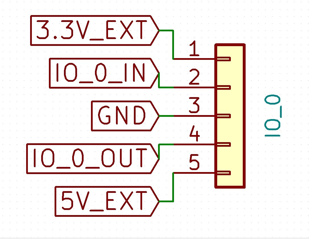
RepRapFirmware 3 can be configured to map these ports to the appropriate functions as required.
Except as noted in the table below, an IO_x_IN pin can always be used to provide a digital input (e.g. for endstop inputs or filament monitors), and an IO_x_OUT pin can always be used to provide a digital output.
Additionally:
- IO output pins can be used as inputs, but are only 3.3V tolerant. When using a io_out pin as an input, you need to either enable the pullup resistor using the ^ character at the start of the port name, or use an external pullup resistor to +3.3V.
- IO input pins can be used as outputs, but have 10K protection resistors in series with them, so you would need to bypass these to use them as outputs. Warning: it can be easy to damage the board irreparably doing this, and modifying your board will invalidate the warranty.
Some ports have further capabilities as shown in this table
¶ Specific capabilities
Capabilities of IO_0 to IO_8 are shown below.
| IO # | UART? | Analog in? | PWM out? | Notes |
|---|---|---|---|---|
| 0 | yes | no | no | Shared with PanelDue header for UART connection |
| 1 | yes | no | no | Shared with RS485 header on v1.02 and later |
| 2 | no | no | no | A jumper is provided to bypass the 10K input protection resistor to allow I2C to be used on this port. Note: RepRapFirmware does not currently support I2C on Duet 3 boards. |
| 3 | no | yes | no | |
| 4 | no | yes | yes | |
| 5 | no | yes | no | |
| 6 | no | yes | no | |
| 7 | no | yes | yes | |
| 8 | no | yes | no |
¶ Opto-isolated IO headers
IO_5-IO_8 are also available as opto-isolated inputs and outputs
¶ Opto-isolated Inputs
The opto-isolated inputs can be wired either NPN or PNP, depending on the requirements of the system they are interfacing with. Note there inputs are designed for digital signals only.
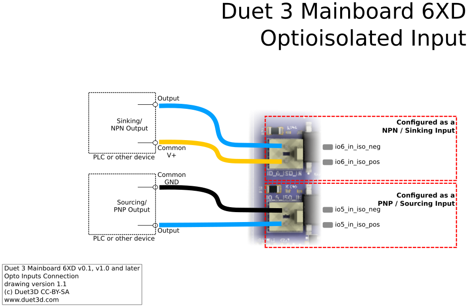
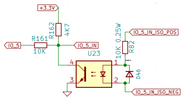
on the Duet 3 Mainboard 6XD the opto-isolated IO 5 input port schematic is as follows, IO6-8 are the same:
¶ Opto-isolated Outputs
The opto-isolated outputs can be wired either NPN or PNP, depending on the requirements of the system they are interfacing with.
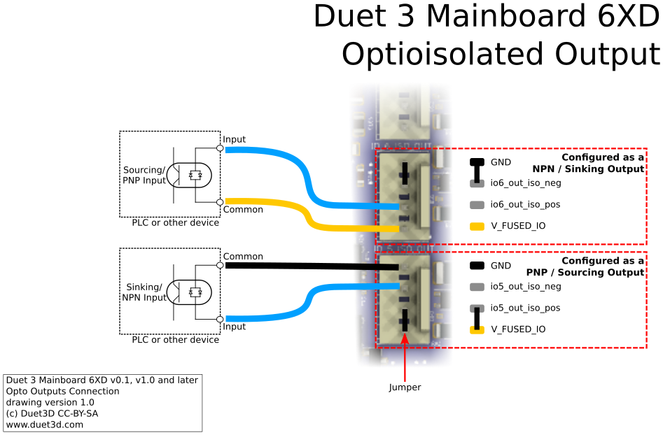
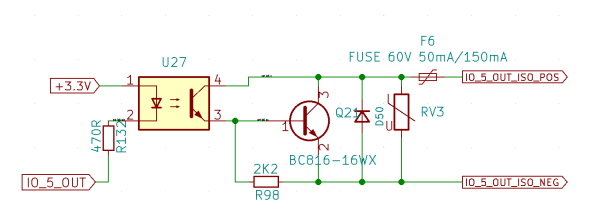
on the Duet 3 Mainboard 6XD the opto-isolated IO 5 output port schematic is as follows, IO6-8 are the same:
¶ RS485 - MODBUS RTU
From board revision v1.02 there is hardware support for a MODBUS RTU from the RS485 header. This is shared with the IO1 GPIO channel so if used then do not connect endstops or anything else to the IO1 signals.
To enable the RS485 transceiver there is an RS485 enable jumper:
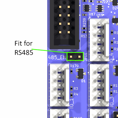
Use M575 to setup the port as MODBUS RTU
See M260.1 and M261.1 for how to read and write to the MODBUS device
¶ Power distribution
¶ VIN (Input voltage from PSU)
Supply 12V-24V input power (11-30V absolute minimum/maximum) between the GND and VIN terminals.
VIN is split via four fuses:
- V_FUSED: 15A : All on board power demands, other than those specified below
- VLC1_FUSE: 3A : OUT3-OUT5 when the select jumper is on VIN
- VLC2_FUSE: 3A : OUT6-OUT8 when the select jumper is on VIN
- VFUSED_IO: 300mA: VIN current for the Opto-isolated Output headers IO_5-IO_8
V_FUSED is distributed across the board as follows:
- 12V Regulator
- 5V regulator
- OUT 0 - OUT 2 headers
If you use a relay to control VIN power to the board, ie the power supply is already switched on, and a relay is used to turn on power to the board, you should use an inrush current limiter wired in series with VIN. See the section on Inrush current here.
OUT ports on the board should NOT be used to switch power to other boards directly. See the note at the end of the 'inrush current' section at the link above.
¶ 12V
The Duet 3 Mainboard 6XD produces 12V onboard from VIN. 12V will not be produced if only 12V is provided as VIN, a minimum of 14V is recommended to use the onboard 12V regulator.
12V_EXT: , Supplied to:
- V_OUTLC1/2 for OUT_3 thru OUT_8.
- 12V header (useful for supplying 12V to a VFD)
Caution on board 12V regulator has a 800mA limit
¶ 5V
5V: Split up to 5V_EXT, 5V_INT. (see 5V input power options below for more details).
- 5V_EXT feeds:
- IO headers
- PanelDue
- LASER/VFD header
- Dotstar header
- 5V_INT feeds:
- Internal and External 3.3V regulators
- External Driver headers
- Internal 5V logic
5V input can come from one of these sources:
- Onboard 5V regulator: Once 3.3V and other onboard demands are met approximately 3A remains for use on the 5V_EXT rail.
- USB: Can supply both 5V_INT and 5V_EXT. limited to 1A
- 5V_EXT_IN: When using EXT_5V_IN, remove the jumper from Int 5V EN to disable the onboard 5V regulator (see below for more details). The EXT_5V header also has a pin for controlling an external power supply. This allows for the board to be powered from 5V, with an external supply for VIN turned on and off as required.
- 5V_SBC: In some, limited, cases it may be desirable to power the board from the 5V output of a SBC connected to the SBC header. Note that the total power of the Duet+ peripherals must be factored into the SBC power budget. See notes below
There is an array of jumpers to customise the 5V power setup as required:
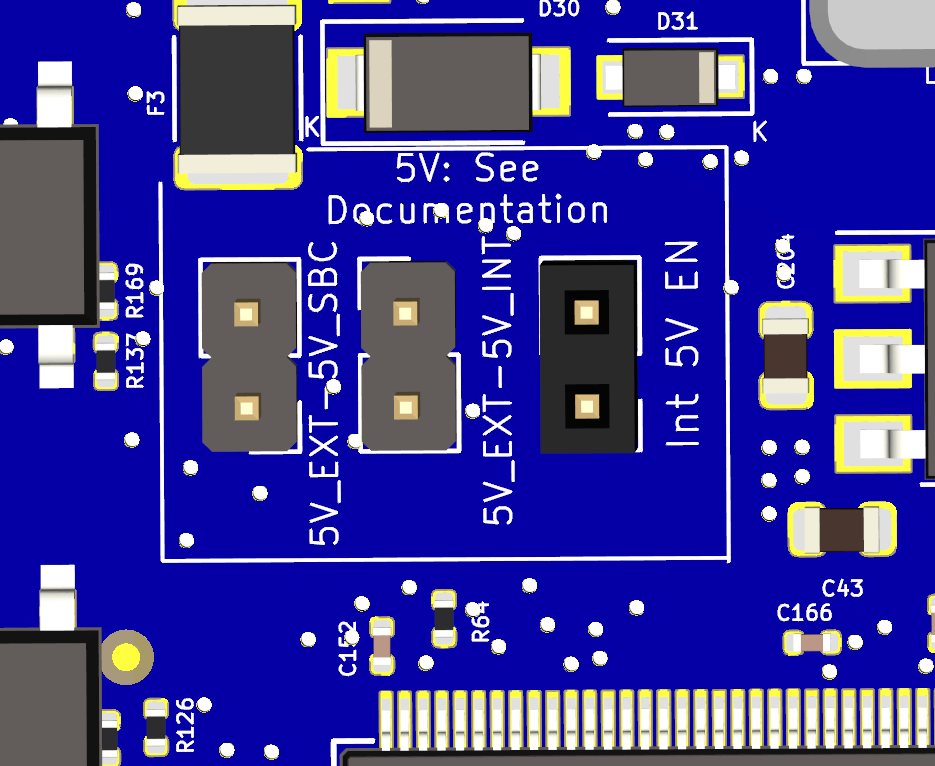
As standard only the Int 5V En jumper header is fitted
Internal 5V only
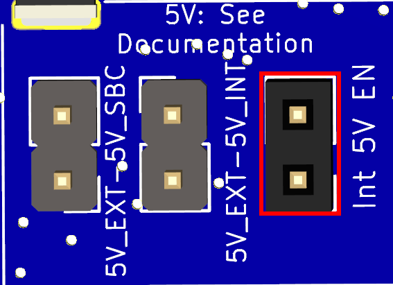
The default configuration has a jumper on the "Int 5V EN" only. This means the internal 5V is enabled but the SBC is not powered by the Duet but from its own power supply. The Duet can supply up to 3.0A to all 5V loads.
Internal 5V & Duet 3 6XD supplying the SBC
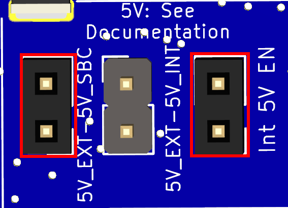
With jumpers on the "Int 5V EN" and "5V_EXT - SBC" pins the internal 5V is enabled and the SBC is powered by the Duet's 5V. The Duet can supply up to 3.0A to all 5V loads including the SBC 1.
This requires the 5V_EXT- SBC jumper header to be fitted to the board as its not fitted as standard.
1 Newer SBCs (e.g. RPi 4) need too much 5V power, especially with a screen, to make it sensible to supply from the Duet. Similarly the spare 5V power budget on the SBC may not be sufficient for the Duet. In addition some SBCs require >5V on the 5V rail to not give an under voltage warning.
SBC supplying 5V to the Duet 3 6XD
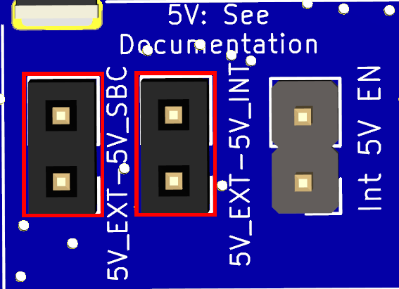
In some, limited, cases it may be desirable to power the board from the 5V output of a SBC connected to the SBC header. Note that the total power of the Duet 3 6XD and peripherals must be factored into the SBC power budget. Jumpers are fitted on the "5V_EXT-5V_SBC" and the "5V_EXT-5V_INT" jumpers.
This requires the 5V_EXT-SBC and 5V_EXT-5V_INT jumper header to be fitted to the board as its not fitted as standard.
CAUTION With the "5V_EXT-5V_INT" fitted the Duet 3 6XD in-built protection for the 5V_INT supply is bypassed.
Powered from 5V_EXT_IN
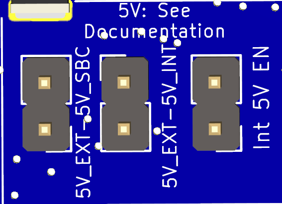
If 5V is being supplied via the 5V_EXT_IN header then disable the onboard 5V regulator. It is possible to fit the 5V_EXT-5V_SBC jumper to pass this power through to the SBC but it is not recommended because of the drop in voltage on the Duet due to protection circuits. It is better to provide a separate 5V connection to the SBC.
Caution! Due to the range of SBC current requirements, along with other external 5V current draws such as Screens, LEDS. It is highly recommended to not use the internal supply on the Duet to power SBCs, hence the jumper headers are not fitted as standard.
¶ SBC 5V considerations
Powering a SBC like the Pi3 from the Duet is feasible provided any USB peripherals attached to the Pi are very low power draw or have their own separate power supply. Higher power draw SBC like the Pi4 may draw more power than the internal 5v on the Duet can supply, especially with added peripherals. In general, for best results, it is recommended to power the Duet and the SBC separately to avoid power overdraw issues.
Furthermore, it is recommended to use a sufficient power supply for the Pi4 that is capable of providing 3A. The official Raspberry Pi Power Supply is a good example of this. Additionally, the USB cable used to power the Pi must be of good quality.
Power overdraw conditions may result in poor communication between the Pi and Duet. The Pi may display a lightning bolt icon on the display (if connected) which is a good indication there is a power supply problem.
¶ 3.3V
+3.3V: Internal 3.3V supply for onboard logic and SPI Daughterboards
3.3V_EXT:
- IO Headers
- External SD card on PanelDue header
¶ Connecting External Motor Drivers
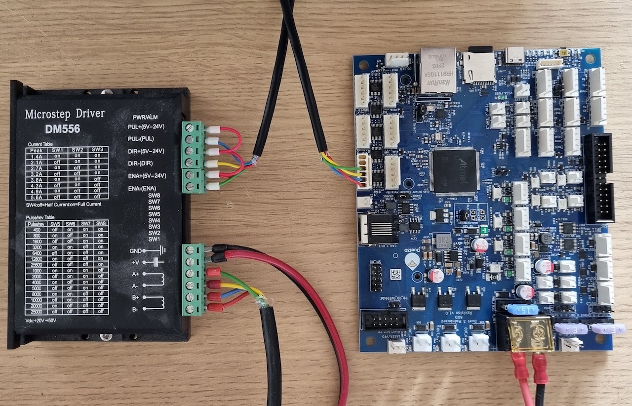
The Duet 3 Mainboard 6XD supports directly connecting external stepper drivers that have opto-isolated or similar inputs. Note that:
- The Step and Dir outputs from the 6XD are either low (when "on") or floating/high-impedance when "off".
- The 6XD will generate negative-going step pulses, and this will only work if the driver samples steps on the leading edge of the pulse. For stepstick and similar drivers, that will depend on the driver chip. Otherwise, add an inverter between the step output and the driver.
- Direction can be flipped using M569 S parameter.
- The Enable output is either low when "on" and high impedance when "off", or vice versa, depending on the position of the 'Driver Enable Polarity' (En_Pol) jumper.
- The jumper sets the default value in case a M569 command with R parameter isn't seen. The main aim of this is to power up with the drivers disabled.
- The
M569 R#parameter overrides the jumper.
R0 = signal not energised to enable the driver. On v1.01 and earlier boards this means high impedance; on v1.02 this means pulled to +5V.
R1 = signal energised to enable the driver. This means the output is pulled to low impedence.
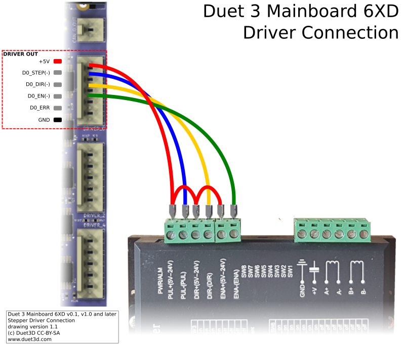
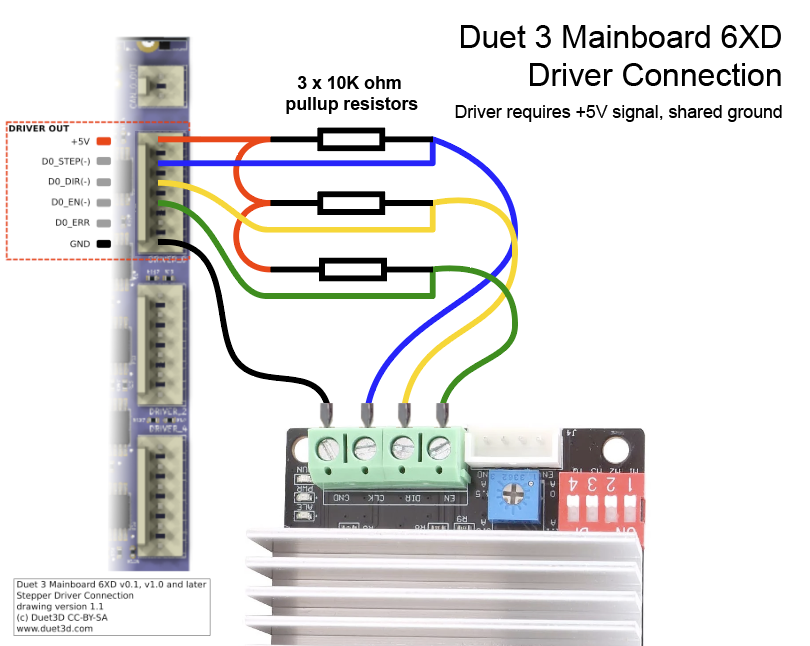
This diagram shows connection to a "typical" optoisolated stepper motor driver
To connect a Pololu/StepStick/similar driver to the 6XD, when using a version 1.01 or earlier 6XD board a 10K pullup resistor is needed from each of the Step/Dir/En lines to +5V. This diagram shows connection to a stepper motor driver that has +5V inputs and a common ground. The resistors are not needed when using a version 1.02 or later board.
For firmware configuration, including mapping drives to axes, configuring enable polarity, and configuring step timing, see the Connecting external stepper and servo drivers wiki page.
¶ Connecting a PanelDue
A PanelDue can be connected to IO_0 using a 4-wire cable. See Connecting a PanelDue
Alternatively, it can be connected using a ribbon cable plugged into the socket labelled PanelDue_SD, which enables access to the PanelDue SD card socket. However, there are some caveats; see note on Duet 3 MB6XD on Connecting a PanelDue.
¶ Connecting a Raspberry Pi
The Raspberry Pi is sensitive to the input voltage, and many smartphone chargers or other USB power supplies cannot supply sufficient voltage. Therefore, we strongly recommend that you use the official Raspberry Pi PSU, or another PSU specifically designed to power a Raspberry Pi. If the red LED on the Pi is not continuously illuminated, the power supply is insufficient.
In other respects, SBC connection to the Duet and configuration is the same as for the Duet 3 Mainboard 6HC. See SBC Setup for Duet 3.
When using an attached Raspberry Pi or other SBC the Ethernet interface on the Duet 3 6XD is disabled.
¶ Connecting Fans
See Connecting and configuring fans.
¶ CAN-FD Bus expansion
The CAN-FD bus provides connectivity to compatible devices. Duet3D manufacture a range of expansion devices. The maximum number of expansion devices on the bus depends on the firmware used; see Firmware configuration limits.
The CAN BUS is connected via RJ11 and at least 2-core twisted pair wiring. 6-core RJ11 wiring is more common, and can be used, though only one pair of wires are used.
The Duet 3 Mainboard 6XD has support for two CAN busses; CAN0 and CAN1. Currently (RRF v3.5 and earlier) only CAN1 is used for connecting CAN-FD Duet 3 Expansion and Tool boards. CAN0 can be used for talking to non-RRF hardware that uses different protocols from that used by Duet 3 boards, including devices that talk plain CAN. Currently it is only used to configure motors for special kinematics.
For further information on CAN connectivity, see CAN connection
¶ Bus termination
There is a 120R bus termination fitted to the CAN-FD bus so normally this board must be at the end of the bus. There are drill-to-disconnect jumpers that allow the termination resistor to be removed, , however this is not required in normal operation. It is only required if a 6XD board is to be used as an expansion board and not placed at the end of the bus but somewhere in between.
¶ Removing the bus termination
On the back side of the board are 2 drill to disconnect jumpers per bus:
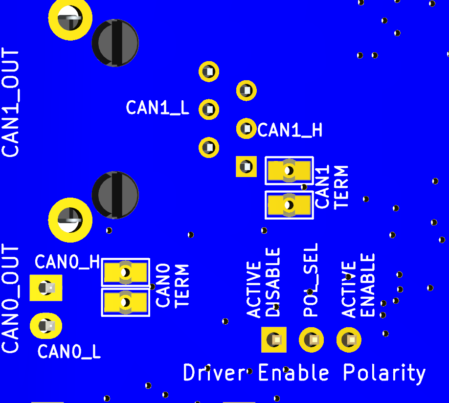
To disconnect the termination resistors, use a small drill bit ~2mm by hand to carefully remove the connection between the two pads that is made with the ring of the copper between the pads. Do not drill all the way through the board, the copper layer is approx 70um thick (i.e. very thin!) once its removed test that the pads are actually disconnected by checking that there is no continuity between them with a voltmeter.
Both jumpers must be disconnected or connected. do not do only one.
If in the future you want to add the termination resistor back into the circuit the jumper can be bridged with solder.
¶ Revision History
- Changed the Step, Dir and Enable outputs to have active pullups for beter compatibility with some servo drivers
- Added hardware support for RS485 on UART 1 shared with IO1), a 3 pin RS485 header and an RS485 enable jumper
- Reset External header position moved slightly.
- Minor changes to USB host support circuit.
- Change the 5V_EXT_SBC and 5V_EXT-5V_INT jumper headers to not be populated y default.
- added hardware to provide USB Host support in future firmware.
- Added a Jumper to connect the external SD card on the PanelDue header to GND (allows older versions of PanelDue with out a card detect pin to be used.
- fixed labelling error with the ACTIVE ENABLE and ACTIVE DISABLE legends on the enable polarity selection jumper, on both sides of the PCB
- Board can now be programmed with BOSSA even when Driver enable polarity select is Enable Active.
- Updated CAN common mode chokes for better performance
- Added termination disconnection cuttable jumpers for CAN 1 to allow the board to not be at the end of the CAN bus.
First prototype.
