¶ Introduction
The Duet 3 Expansion 1HCL board provides a high current Stepper motor driver, combined with multiple interfaces for position feedback and firmware to implement closed loop position control. In addition it has a number of peripheral inputs and outputs for functions such as sensing motor temperature, controlling a brake and axis endstop. It connects to the Duet 3 CAN-FD bus using RJ11 connectors (same as the Duet 3 Mainboard 6HC, Duet 3 expansion boards, and the tool distribution board). Multiple Duet 3 Expansion 1HCL boards can be daisy chained on the bus, with power (up to 48V) provided locally. This allows for very large machines to be constructed without a significant wiring burden and signal integrity issues.
¶ Features
¶ Hardware specification
| Processor | Microchip ATSAME51G19A |
| Processor features | 32-bit, 120MHz ARM Cortex-M4F, 512Kb flash, 192Kb RAM, hardware single precision floating point unit |
| Networking/Comms | CAN-FD BUS for connection to the Duet 3 Mainboard. Optional on-board CAN bus termination. |
| On-board stepper driver | 1 x TMC2160A |
| Stepper driver features | SPI controlled, can be run in open loop or closed loop mode. Maximum motor current 6.3A peak per phase (4.45A RMS). |
| Encoder Inputs | Single Ended/Differential Quadrature or SPI bus |
| Thermistor/PT1000 inputs | 2 x thermistor/PT1000 inputs. This is intended to allow for motor temperature monitoring, potentially coupled with a cooling system controlled by one of the outputs. |
| Medium current output | 1 x medium-current (2.5A max) output at V_FUSED or VA_FUSED (V_AUX with fuse protection) voltage, with PWM capability and built-in flyback diodes. |
| Brake output | 1 x Brake Solenoid (1A max) output at V_FUSED or VA_FUSED voltage. This circuit is designed to turn on/off very quickly to allow for fast brake engagement. It has PWM capability so can be configured to support 24V brakes when V_IN is 48V. Alternatively provide V_AUX at 24V for the brake. (note before v2.0 this output was OUT1 so could be used for a brake or other purpose, without the fast turn off) |
| Inputs/Outputs | 2 x 3.3V-level PWM capable output (3mA max), 2 x digital inputs, protected against over-voltage. Example use: endstop switches. |
¶ Operating limits
Absolute maximums:
| Input voltage | 24V to 50V |
| VIN current limit | 5A maximum (fused limit) |
| Fuses | 5A for V_IN to V_FUSED (max 5A), 5A for V_AUX to VA_FUSED |
| Stepper driver | Up to 6.3A peak current per phase (4.45A RMS per phase; max. standstill current 4.45A) |
| Medium current output | OUT0 up to 2.5A |
| Brake output | up to 1A |
| Inputs/Outputs | Inputs are 30V-tolerant |
| 12V current limit | 200mA |
| 5V and 3.3V current limit | 100mA total on 5V and 3.3V |
| Maximum ambient temperature | 70°C |
Absolute maximums:
| Input voltage | 24V to 50V |
| VIN current limit | 10A maximum (fused limit) |
| Fuses | 10A for V_IN to V_FUSED (max 10A), 5A for V_BRAKE to VB_FUSED |
| Stepper driver | Up to 6.3A peak current per phase (4.45A RMS per phase; max. standstill current 4.45A) |
| Medium current outputs | OUT0/1 up to 2.5A each |
| Inputs/Outputs | Inputs are 30V-tolerant |
| 12V current limit | 200mA |
| 5V and 3.3V current limit | 100mA total on 5V and 3.3V |
| Maximum ambient temperature | 70°C |
¶ Compatible motors
Use motors with 1.8 or more degrees per step. We advise against using 0.9deg motors because the maximum speed will be reduced. The positioning accuracy in closed-loop mode depends on the resolution of the encoder, not on the degrees/step of the motor.
The maximum speed at which the firmware can drive the motor reliably in closed loop mode is about 5000 full steps/second. However, the maximum step rate may be much lower if the driver is not able to change the motor current fast enough because of high motor inductance.
The calculator at https://www.reprapfirmware.org/emf.html will estimate the maximum speeds for which full torque is available for a given motor and supply voltage. Good closed loop operation will typically be available up to the "high slip angle" speed.
¶ Compatible Encoders
RRF 3.4 supports quadrature motor shaft encoders only. RRF 3.5 and later also support Duet3D magnetic shaft encoders and linear composite encoders.
Encoder resolutions of over 1000PPR (Pulses Per Revolution) or 4000CPR (Counts Per Revolution) are highly recommended. Note that generally PPR = CPR/4. Resolutions below this are unlikely to work well in most situations.
The Duet3D magnetic encoder is the most straightforward to calibrate.
¶ Quadrature motor shaft encoders
Stepper motors can be purchased with integral optical shaft encoders. It is also possible to buy add-on quadrature shaft encoders, which are typically mounted on the back of dual-shaft stepper motors. The resolution is specified in counts or pulses per motor revolution. There must be an integer number of output pulses from the encoder per 4 full steps. For example, a 1.8deg/step motor (200 full steps/rev) could have an encoder with 1000PPR (20 pulses per 4 full steps), 2000PPR (40 pulses per 4 full steps) or 2500PPR (50 pulses per 4 full steps).
¶ Duet3D magnetic motor shaft encoders
The Duet3D magnetic encoder is a small board that mounts on the back of the stepper motor. It is supplied with a diametrically-magnetised disc magnet, which must be glued to the centre of the end of the shaft at the back of the motor. A jig should be used to centre the magnet accurately while the glue sets. More details available on the documentation page.
¶ Linear composite encoder
A linear composite encoder comprises a linear quadrature encoder that tracks position on a linear axis (for example the Renishaw LM10IA or LM10IB) and a Duet3D magnetic shaft encoder. The shaft encoder handles motor commutation, the linear encoder is used to close the loop.
¶ Operating modes
The Expansion 1HCL board supports the following modes of motor control:
- Open loop mode. In this mode the driver behaves in a similar way to the drivers on the 6HC main board. If an encoder has been connected and calibrated then it is possible to collect data on the position error for short periods.
- Closed loop mode. In this mode an error signal is computed from the difference between the desired motor position and the position reported by the encoder. This error signal is used to apply a torque to correct the error via a modified PID controller. Warning and error events can be generated when the error exceeds configurable thresholds. When the controller is unable to achieve the desired position, it will recover to the correct position when either the obstruction is removed or a command is sent to move the axis or extruder to a position that can be achieved. Maximum speed is reduced compared to open loop mode; a reasonable predictor of maximum speed is the "Speed at which torque starts to drop (high slip angle)" reported by our motor EMF estimator at https://www.reprapfirmware.org/emf.html, or the speed that corresponds to about 5000 full steps per second if that is lower. The PID controller must be tuned for best response.
- Assisted open loop mode (supported in firmware 3.5.0-beta.4 and later only). In this mode the motor is operated as if in open loop mode, but whenever it is detected that the error between desired and actual position is getting too high, the motor current is automatically increased until the error is reduced. This allows a low initial current to be used, which makes the motor quieter at standstill and low motor speeds. As with closed loop mode, warning and error events can be generated when the error exceeds configurable thresholds. However, if the position requested cannot be achieved and the error exceeds approximately 4 full motor steps, the position will not be corrected when the obstruction is removed or the motor is commanded to a position that can be reached. No further out-of-position events will be generated until the command to enter assisted open loop mode is repeated. Unlike closed loop mode, good operation can be achieved with little or no tuning.
¶ Firmware notes
- Compatible RepRapFirmware versions: RRF 3.4 and later
- Firmware limitations: See Duet 3 with CAN expansion firmware configuration limitations.
¶ Open source
- The Duet3 1HCL is Open Hardware, see our license here.
- All hardware source files are available on Github.
- The Duet hardware and RepRapFirmware are built with Open tools: designed in KiCad and Eclipse using open tools means the barrier to getting involved is as low as possible.
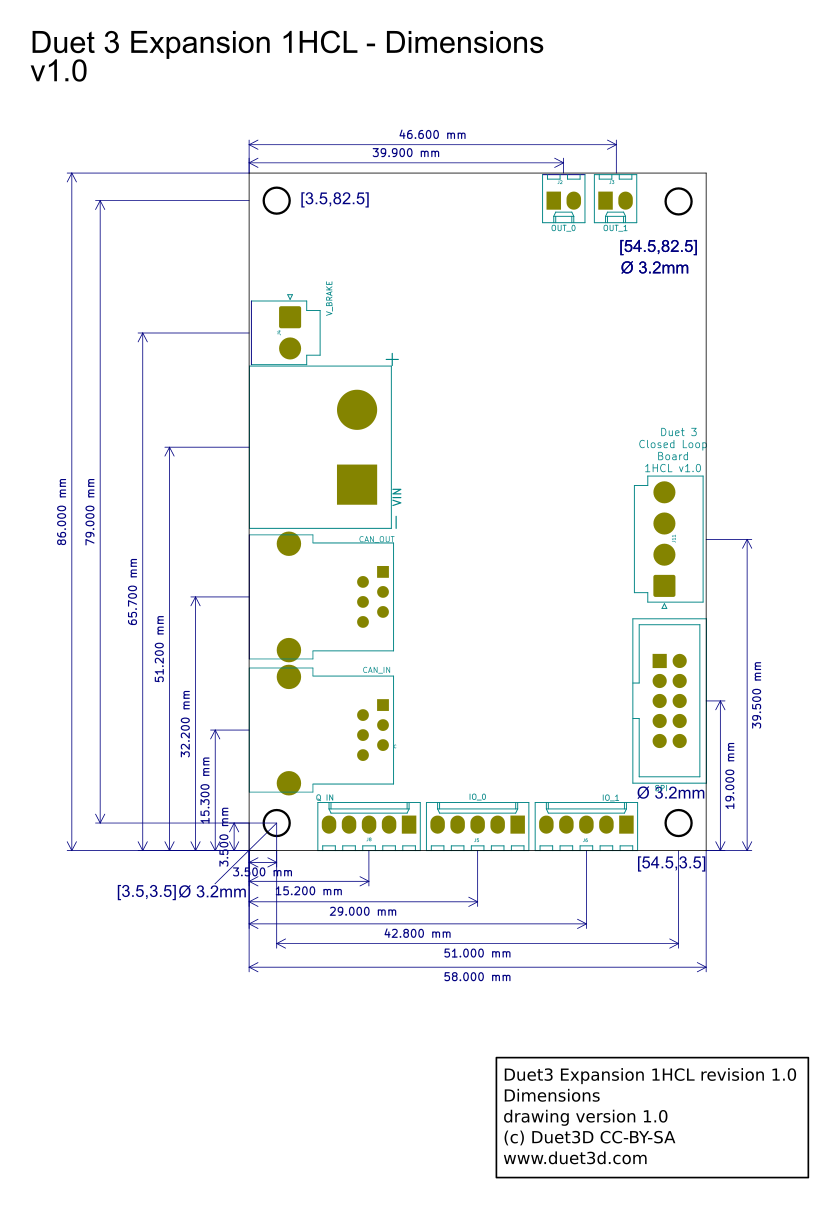
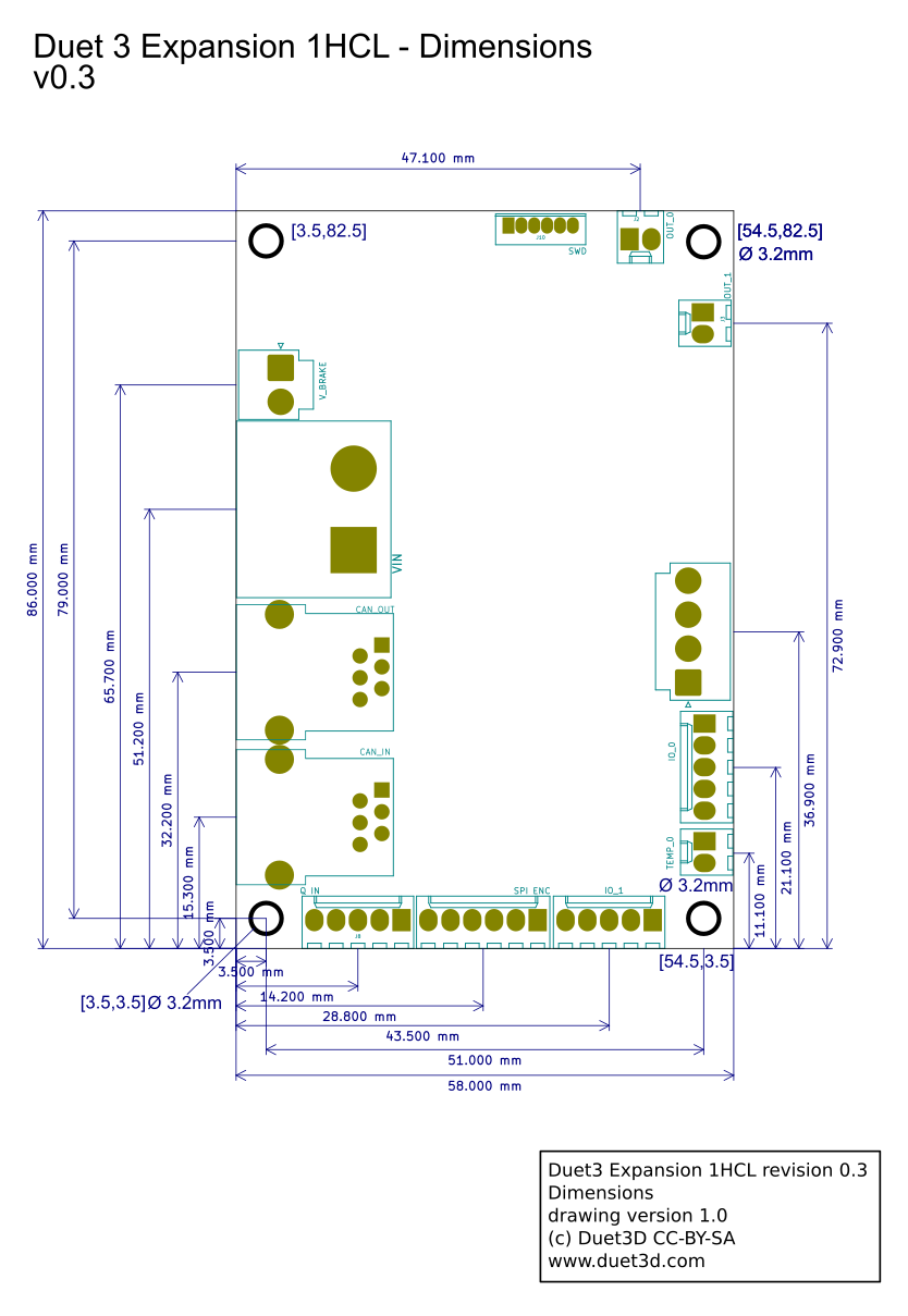
¶ Physical properties
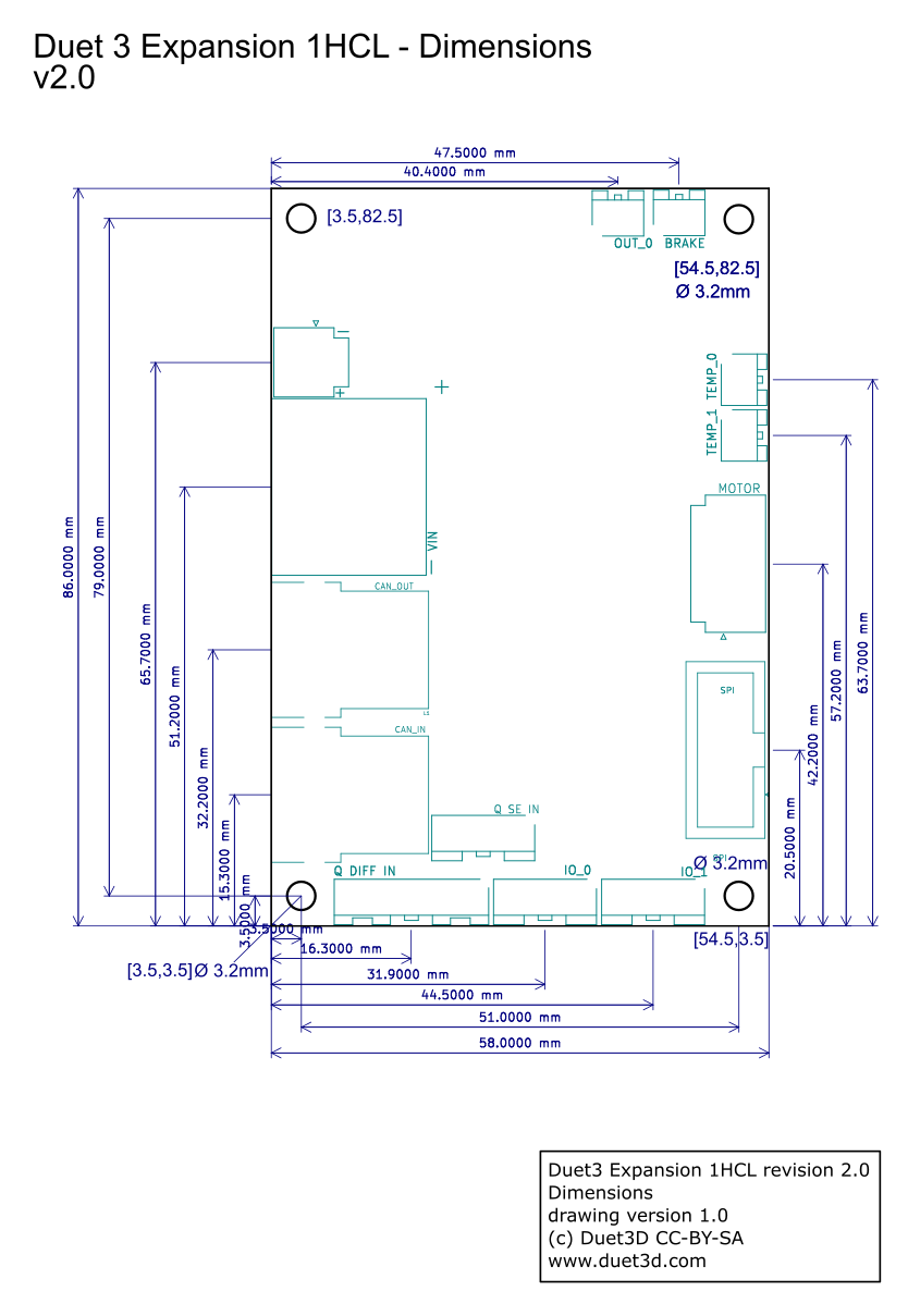
¶ Dimensions
¶ Physical connections
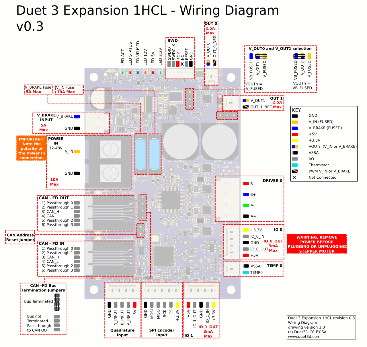
¶ Wiring Diagram
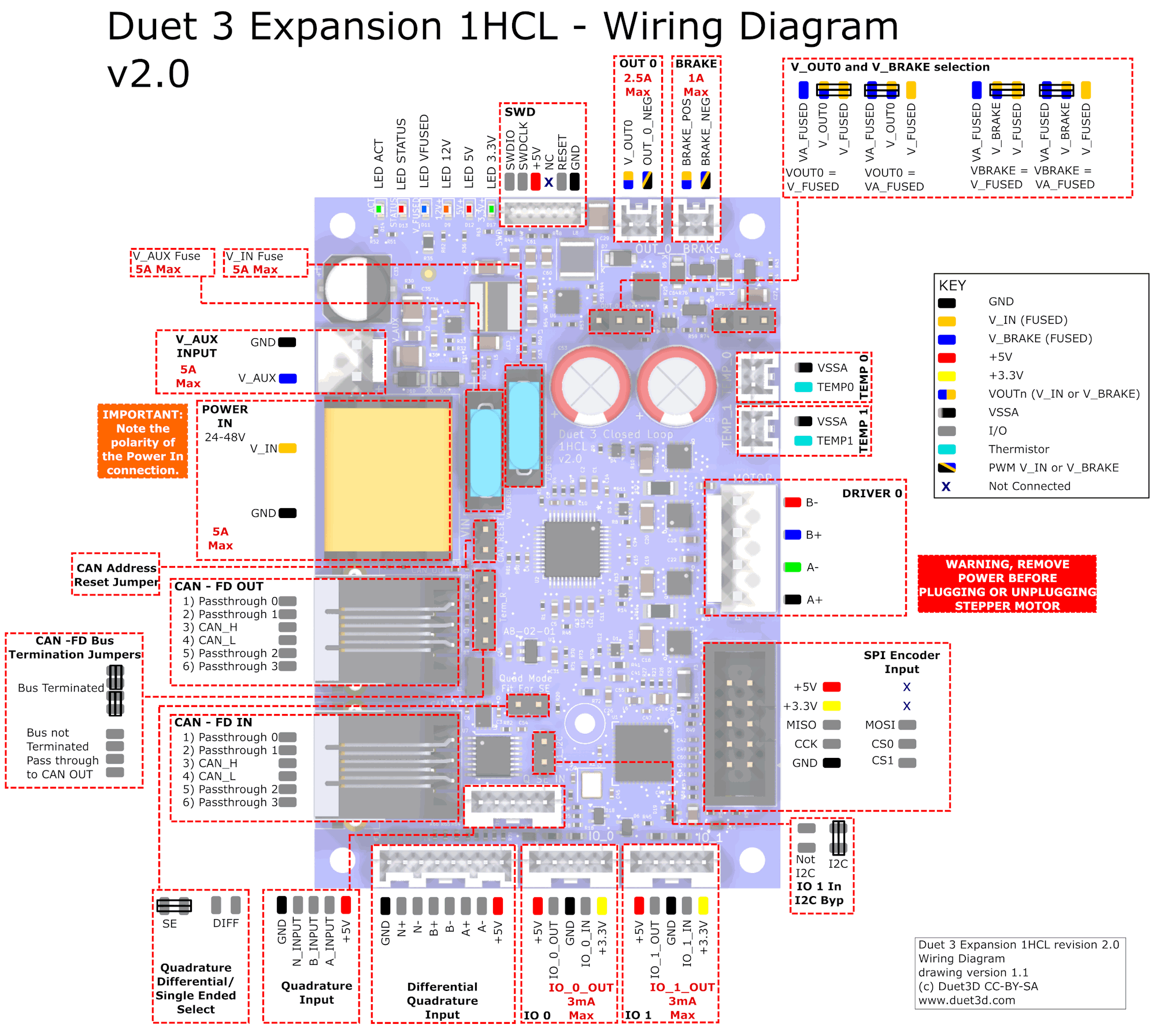
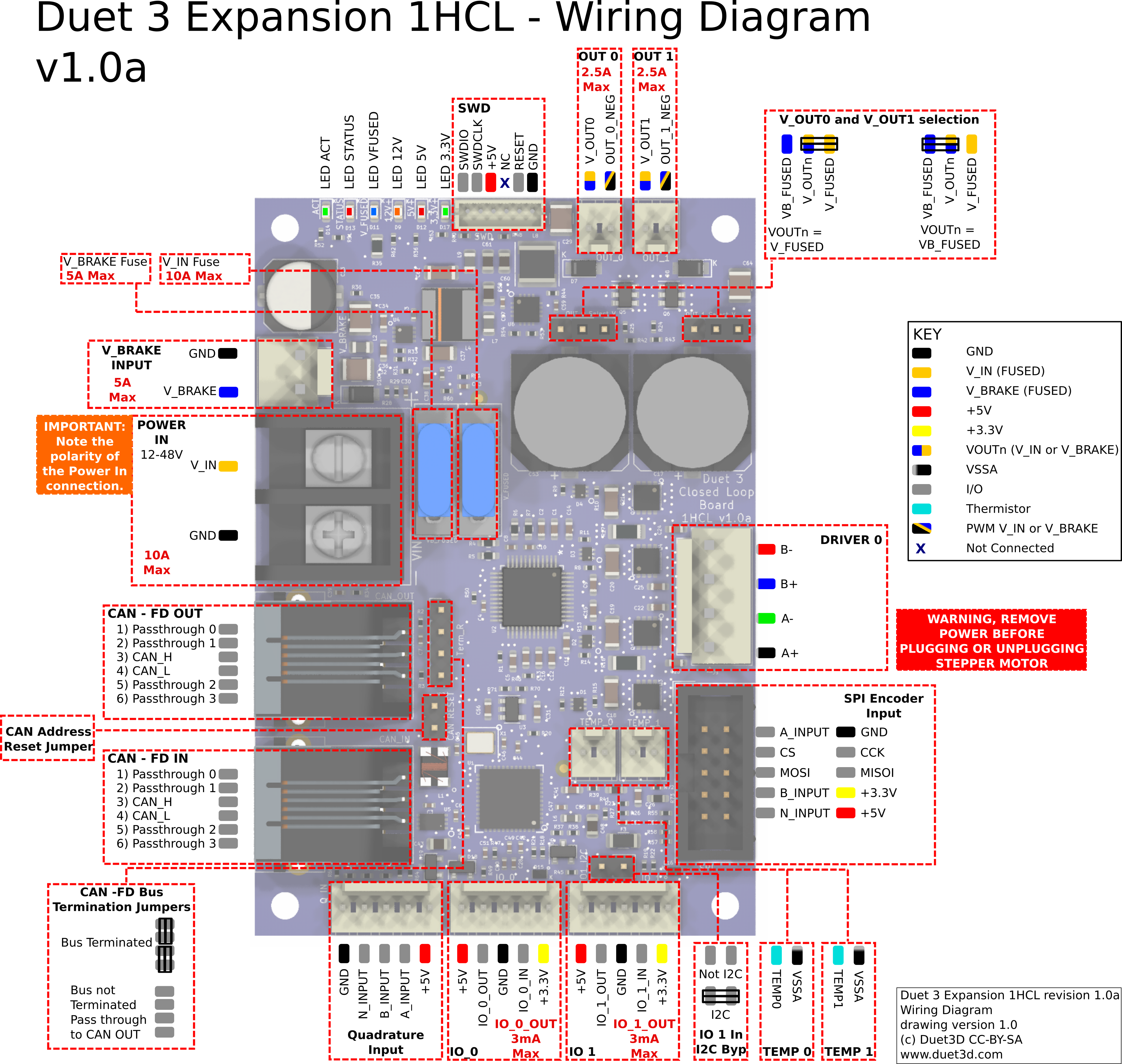
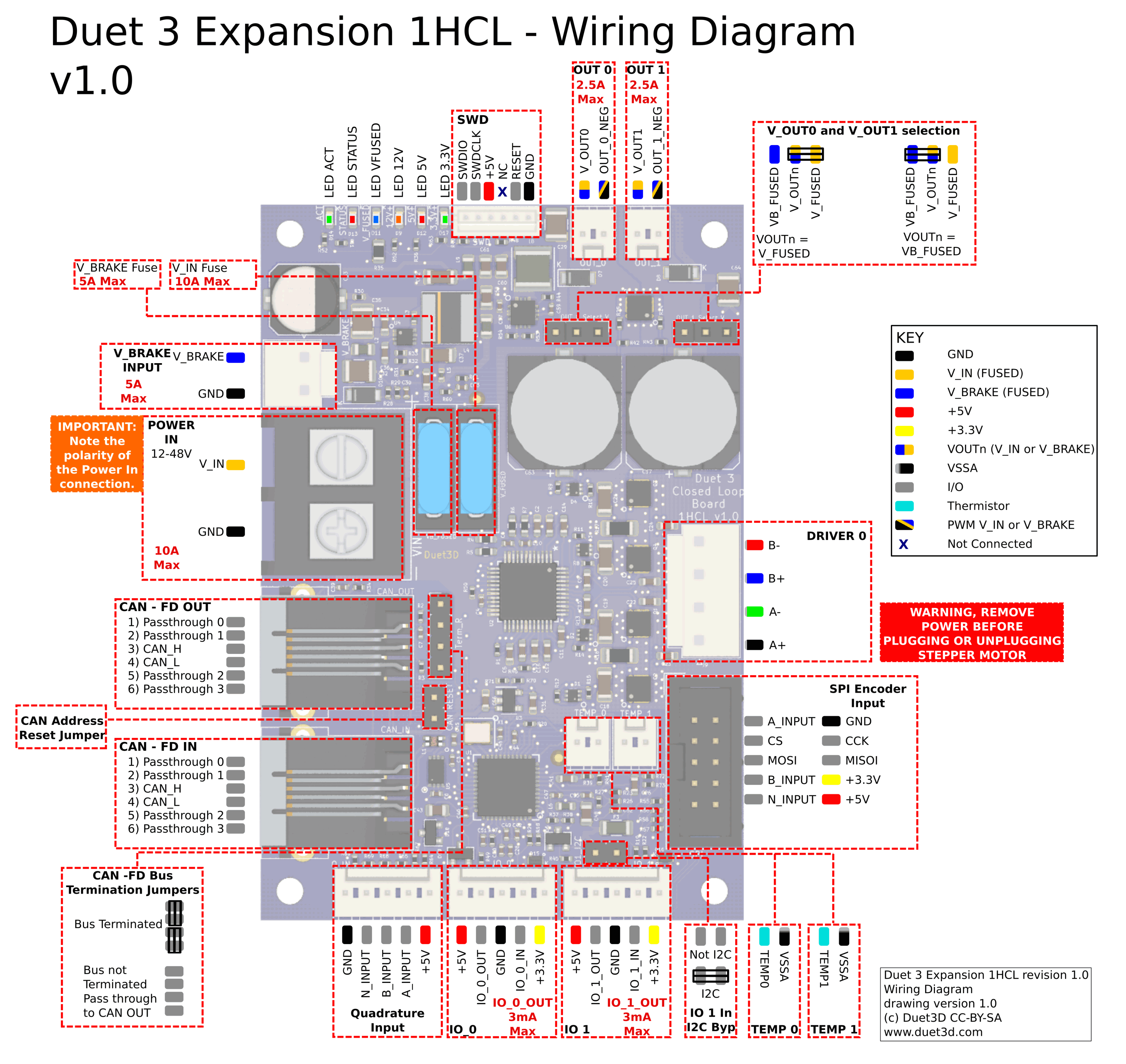
¶ Wiring Notes
- The 4 wire motor is a JST VH series connector. These require a minimum of 22AWG wire (20AWG or 0.5mm2 recommended. Most NEMA17 size stepper motor wire will not be thick enough to use in the normal way; but you can double the stripped part of the wire back on itself to bulk it up, and put a small length of heatshrink sleeving over the insulation to bulk up the insulation. You will need a suitable crimping tool for the crimp pins, for example Engineer PA21 (use the 2.2mm jaw opening to crimp the bare wire and the 2.5mm on to crimp the insulation). Alternatively you can solder the wire to the crimp pin.
¶ Description of Connections
Duet 3 Expansion 1HCL provides the following connectors:
| Header | Label | Function |
|---|---|---|
| 1 x 2-way barrier strip | VIN, GND | Two screw terminals for VIN and GND. Max voltage 50V, max current 5A (fused limit) |
| 1 x 2-pin JST VH connector | V_AUX, GND | Input for auxiliary voltage. This can provide an alternative input for the brake. It can also continue to power the 12V and thence 5V and 3.3V rails, while VIN is shut down. This allows for logic and closed loop position tracking to continue while the motor and output circuits are shut down. See the description on Auxiliary Voltage input below. Max voltage 50V, max current 5A (fused limit) |
| 1 x 6-pin JST ZH (ZHR-6) connector | SWD | This is for firmware debugging |
| 1 x 2-pin JST PA connector | OUT_0 | Intended for PWM-controllable devices (fans, heaters etc). Max current: 2.5A |
| 1 x 3-pin jumper | OUT_0_Select_V | The positive supply to the OUT_0 connector is the centre pin of this 3-pin jumper block. A jumper in the left position will power it from the fused VIN supply (V_FUSED), or a jumper in the right position will power it from the fused V_AUX supply (VA_FUSED). Alternatively you can connect a 3-terminal buck regulator to the 3-pin jumper block to supply the required voltage to the centre pin. |
| 1 x 2-pin JST PA connector | BRAKE | Intended for a motor brake, Max current: 1A. See the section on motor brake voltage control below for more details about using >24V as V_BRAKE with a 24V brake |
| 1 x 3-pin jumper | BRAKE_Select_V | The positive supply to the BRAKE connector is supplied from the centre pin of this 3-pin jumper block. A jumper in the left position will power it from the fused VIN supply (V_FUSED), or a jumper in the right position will power it from the fused V_AUX supply (VA_FUSED). |
| 1 x 4-pin JST VH connector | DRIVER 0 | Stepper motor connections. (See note on JST VH connectors in 'Wiring notes' above.) |
| 1 x 2x5 IDC connector | SPI | SPI encoder input/ SPI Daughterboard header - compatible with SPI daughterboards such as the PT100 and Thermocouple daughterboard |
| 1 x 2-pin JST PA connector | TEMP_0 | Connections for thermistor or PT1000 sensors |
| 1 x 2-pin JST PA connector | TEMP_1 | Connections for thermistor or PT1000 sensors |
| 1 x 5-pin JST PA connector | IO_1 | These are for endstop switches, Z probes, filament monitors, servos, and other low-voltage I/O functions. Each connector provides both 3.3V and 5V power. The inputs will tolerate up to 30V. The outputs are 3.3V signal levels with 470R series resistors. |
| 1 x 2-pin jumper | IO1_I2C | Add a jumper to bypass the 10k resistor on IO1.in, so it can be used for I2C. |
| 1 x 5-pin JST PA connector | IO_0 | These are for endstop switches, Z probes, filament monitors, servos, and other low-voltage I/O functions. Each connector provides both 3.3V and 5V power. The inputs will tolerate up to 30V. The outputs are 3.3V signal levels with 470R series resistors. |
| 1 x 8-pin JST PA connector | Q_DIFF_IN | Differential quadrature encoder input |
| 1 x 5-pin JST PA connector | Q_SE_IN | Single ended quadrature encoder input |
| 1 x 2-pin jumper | Quad Mode Fit For SE |
Add a jumper to select singled ended quadrature encoder mode, remove the jumper to use differential quadrature encoder mode |
| 1 x RJ11 CAN connector | CAN_IN | RJ11 CAN connector |
| 1 x RJ11 CAN connector | CAN_OUT | RJ11 CAN connector |
| 1 x 2-pin JST PA header | CAN RESET | CAN address reset jumper. See 'Commissioning' section below. |
| 1 x 4-pin jumper | Term_R | CAN bus termination jumpers. See CAN connection basics. |
| Header | Label | Function |
|---|---|---|
| 1 x 2-way barrier strip | VIN, GND | Two screw terminals for VIN and GND. Max voltage 50V, max current 10A (fused limit) |
| 1 x 2-pin JST VH connector | V_BRAKE, GND | Input for separate voltage for brake. Max voltage 50V, max current 5A (fused limit) |
| 1 x 6-pin JST ZH (ZHR-6) connector | SWD | This is for firmware debugging |
| 1 x 2-pin KK connector | OUT_0 | Intended for a motor brake, or other PWM-controllable devices (fans, heaters etc). Max current: 2.5A |
| 1 x 3-pin jumper | OUT_0_Select_V | The positive supply to the OUT_0 connector is the centre pin of this 3-pin jumper block. A jumper in the left position will power it from the fused VIN supply (V_FUSED), or a jumper in the right position will power it from the fused V_BRAKE supply (VB_FUSED). Alternatively you can connect a 3-terminal buck regulator to the 3-pin jumper block to supply the required voltage to the centre pin. |
| 1 x 2-pin KK connector | OUT_1 | Intended for a motor brake, or other PWM-controllable devices (fans, heaters etc). Max current: 2.5A |
| 1 x 3-pin jumper | OUT_1_Select_V | The positive supply to the OUT_1 connector is the centre pin of this 3-pin jumper block. A jumper in the left position will power it from the fused VIN supply (V_FUSED), or a jumper in the right position will power it from the fused V_BRAKE supply (VB_FUSED). Alternatively you can connect a 3-terminal buck regulator to the 3-pin jumper block to supply the required voltage to the centre pin. |
| 1 x 4-pin JST VH connector | DRIVER 0 | Stepper motor connections. (See note on JST VH connectors in 'Wiring notes' above.) |
| 1 x 2x5 IDC connector | SPI | SPI encoder input |
| 1 x 2-pin KK connector | TEMP_0 | Connections for thermistor or PT1000 sensors |
| 1 x 2-pin KK connector | TEMP_1 | Connections for thermistor or PT1000 sensors |
| 1 x 5-pin KK connector | IO_1 | These are for endstop switches, Z probes, filament monitors, servos, and other low-voltage I/O functions. Each connector provides both 3.3V and 5V power. The inputs will tolerate up to 30V. The outputs are 3.3V signal levels with 470R series resistors. |
| 1 x 2-pin jumper | IO1_I2C | Add a jumper to bypass the 10k resistor on IO1.in, so it can be used for I2C. |
| 1 x 5-pin KK connector | IO_0 | These are for endstop switches, Z probes, filament monitors, servos, and other low-voltage I/O functions. Each connector provides both 3.3V and 5V power. The inputs will tolerate up to 30V. The outputs are 3.3V signals level with 470R series resistors. |
| 1 x 5-pin KK connector | Q_IN | Quadrature encoder input |
| 1 x RJ11 CAN connector | CAN_IN | RJ11 CAN connector |
| 1 x RJ11 CAN connector | CAN_OUT | RJ11 CAN connector |
| 1 x 2-pin KK header | CAN RESET | CAN address reset jumper. See 'Commissioning' section below. |
| 1 x 4-pin jumper | Term_R | CAN bus termination jumpers. See CAN connection basics. |
¶ LED indications
LEDs are provided to indicate the following:
| Label | Colour | Function |
|---|---|---|
| ACT | Green | Indicates activity on the CAN-FD bus |
| STATUS | Red | See description below |
| V_FUSED | Blue | Indicates fused VIN supply present |
| 12V+ | Amber | Indicates indicates on-board 12V regulator operating |
| 5V+ | Red | Indicates indicates 5V supply present |
| 3.3V+ | Green | Indicates on-board 3.3V regulator operating |
The red LED labelled "STATUS", next to the Reset button, indicates the state of the board, as follows.
STATUS LED: In normal use, the red LED flashes slowly in sync with the main board to indicate that it has CAN sync, or flashes continuously and rapidly to indicate that it doesn't. It also flashes startup error codes, for example if the bootloader doesn't find valid firmware on the board. For a list of these error codes see CAN_connection basics.
¶ Pin names
For more information on pin names, see Pin Names.
RepRapFirmware 3 uses pin names for user-accessible pins, rather than pin numbers, to communicate with individual pins on the PCB. In RRF 3 no user-accessible pins are defined at startup by default. Pins can be defined for use by a number of gcode commands, eg M574, M558, M950.
The Duet 3 series uses the pin name format "expansion-board-address.pin-name" to identify pins on expansion board, where expansion-board-address is the numeric CAN address of the board. A pin name that does not start with a sequence of decimal digits followed by a period, or that starts with "0." refers to a pin on the Duet 3 Mainboard.
| Function | Pin location | Pin name | Notes |
|---|---|---|---|
| Outputs | OUT_0 | out0 | PWM |
| OUT_1 | out1 | V1.0/V1.01a ONLY PWM | |
| Brake | BRAKE | brake | V2.0 ONLY PWM, use in the M569.7 Command as the brake port |
| Inputs/Outputs | IO_0 | io0.out | PWM |
| io0.in | analog/digital input | ||
| IO_1 | io1.out | PWM | |
| io1.in | digital input | ||
| Quadrature Input | pdec.a | used to connect a quadrature encoder. If no quadrature encoder is connected then they are available as digital inputs. | |
| pdec.b | |||
| pdec.n | |||
| SPI Encoder Input | pdec.a | V1.0/V1.01a ONLY Common with the Quadrature Input header. | |
| pdec.b | |||
| pdec.n | |||
| spi.cs0 | CS signal for the SPI encoder or for an SPI DB | ||
| spi.cs1 | V2.0 ONLY CS signal for an SPI DB | ||
| TEMP_0 | temp0 | 2K2 pullup + filter, intended for thermistor/pt1000 | |
| TEMP_1 | temp1 |
¶ Input/Output
OUT_0 and OUT_1 are PWM-capable.
The individual IO_x connectors have the following capabilities:
| IO # | UART/I2C? | Analog in? | PWM out? | Notes |
|---|---|---|---|---|
| IO_0 | No | Yes | Yes | |
| IO_1 | Yes1 | No | Yes | Note: RepRapFirmware does not currently support UART or I2C on Duet 3 expansion/tool boards. |
| pdec.a, pdec.b. pdec.n | No | No | No | digital inputs |
1 UART serial connection is not currently supported in RepRapFirmware for expansion/tool boards. While io1 in/out are theoretically capable of I2C, this also is not implemented in RepRapFirmware at present.
¶ Power wiring
Supply between 12V and 48V to the V_IN 2-way barrier strip power connector on the board, observing the correct polarity.
If you use a relay to control VIN power to the board, ie the power supply is already switched on, and a relay is used to turn on power to the board, you should use an inrush current limiter wired in series with VIN. See the section on Inrush current here.
OUT ports on the mainboard should NOT be used to switch power to expansion or tool boards directly. See the note at the end of the 'inrush current' section at the link above.
¶ Auxiliary Voltage Input
In some cases it is desirable to provide a separate voltage input to the board that remains on when V_IN is removed. This can be the case for setups when a safety circuit needs to cut the motor power immediately (i.e. an E-Stop). In those cases it may be desirable to maintain the logic circuitry running on the 1HCL and continue to read the encoder so that position tracking can be maintained. To do this provide 12V or greater to the V_AUX input.
Note this is available on v2.0 boards only. On earlier boards this input was labelled "V_BRAKE" and designed to provide an alternative voltage to the output ports, predominantly for 24V brakes. See the section on Motor Brake Voltage below.
¶ Motor Brake Voltage
It is possible to use a V_IN voltage higher than 24V to be used with a 24V brake.
Proceed with caution, always test these examples with low motor current and slow speeds first
When the motor driver is enabled, the specified output port will be turned on at the same time to release the brake. When the motor driver is disabled, the output port will be turned off. Idle current mode does not count as disabled.
After M569.7 is executed, the port will be initially off. Therefore, M569.7 should be executed before the motor is first enabled.
Use M569.7 to setup the brake PWM pin, and specify the voltage as follows:
M569.7 P50.0 C"brake" V24 ; driver 0 on 1HCL v2.0 at address 50 uses the brake port to control a 24V brake.
On v2.0 boards this is a fast brake control circuit designed to allow the brake to be engaged very quickly by dumping the energy the current in the brake solenoid coil.
On v1.0/v1.0a boards use out1 or out0 as normal outputs:
M569.7 P50.0 C"out0" V24 ; driver 0 on 1HCL v2.0 at address 50 uses the out0 port to control a 24V brake.
Alternatively supply V_AUX (v2.0) or V_BRAKE (v1.0) with 24V and set the voltage select jumper to use that voltage.
To use the voltage adjustment feature of M569.7 always jumper the brake to V_IN. Do not supply V_AUX/V_BRAKE with higher than the voltage of your brake and then use that to power the brake - V_AUX/V_BRAKE is not monitored so M569.7 cannot adjust the voltage using PWM in that case.
¶ Encoders
¶ Quadrature encoder
The 1HCL supports a quadrature encoder connected to the Quadrature Input interface. This works with common 5V, 1000PPR-2500PPR optical encoders that are frequently supplied with closed loop stepper motors. (One example is the 17E1K-05), however there are many other examples).
¶ Connecting a Quadrature Shaft Encoder
Quadrature encoders (which may use optical or magnetic technology) have either a differential output (often shown as A+,A-, B+,B-,N+,N- or as A,A',B,B',N,N') or a single ended output. The Duet 3 Expansion 1HCL v2.0 has both an 8-pin connector for differential and a 5 pin connector for single ended signals (v1.0/v1.0a have only a 5-pin connector for single ended quadrature signals.
Note the index signal (N or Z) is not currently used
Here is a picture (courtesy of LDO motors) which shows a single ended and differential encoder output:
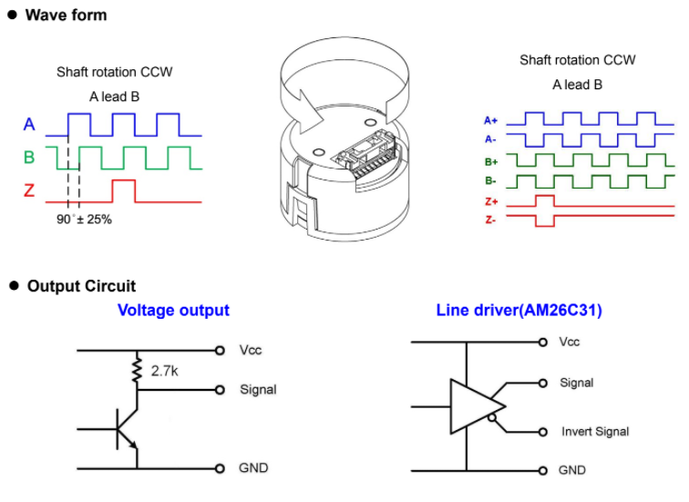
¶ Single Ended
If the encoder has a single ended output then the signal lines connect to the 1HCL 5 pin single ended input: A to A_INPUT, B to B_INPUT, and 5V or VCC to the +5V and ground to ground. The Z or N can be left disconnected while the index pulse is not supported in firmware.
¶ Differential
If the encoder has a differential output then connect the A- to A-, A+ to A+ etc. 5V/VCC to 5V and ground to ground. The Z+Z-/N+N- can be left disconnected while the index pulse is not supported in firmware.
If the encoder has a differential output then connect the A+ to , B+ to the signal inputs on the 1HCL. 5V/VCC to 5V and ground to ground. The A-,B- and Z+Z-/N+N- can be left disconnected while the index pulse is not supported in firmware.
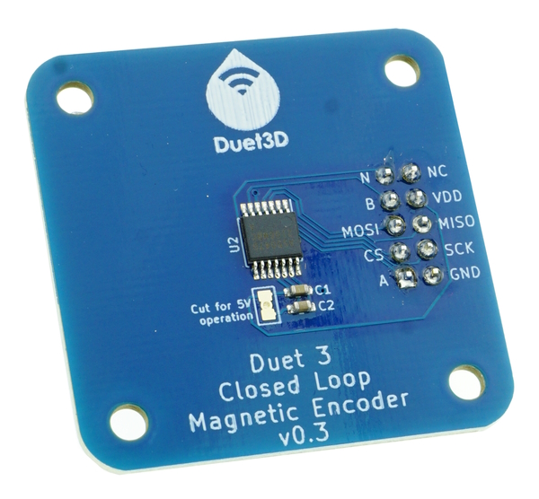
¶ Duet3D Magnetic Shaft Encoder
This support is available from RRF 3.5
The Duet 3 Expansion 1HCL supports the Duet3D Magnetic Encoder. We supply this encoder on a Nema17 form factor PCB, designed to sense a diametrically magnetised magnet glued to the back of the motor shaft. We have also used this encoder board on a Nema23 motor using a printed adapter.
Connect the encoder board to the Duet 3 Expansion 1HCL to the 10-way box connector using a 10-way straight-through ribbon cable. The cable length should not exceed 200mm.
See the Duet3D Magnetic Encoder documentation for more information.
¶ Linear quadrature encoder plus Duet3D Magnetic Shaft Encoder
This support is available on an experimental basis in RRF 3.5
Attach and connect the Duet3D magnetic shaft encoder as described above. Connect the linear quadrature encoder to the quadrature encoder input as described above for a quadrature shaft encoder.
¶ Commissioning
All boards in the system must have different CAN addresses. 1HCL boards are shipped set to a default CAN address of 123. They will also revert to 123 if you use the jumper to force the bootloader to request new firmware. Therefore, if you have more than one new 1HCL board, only one of them must be powered up and connected to the CAN bus. So disconnect power to all but one of them (you can leave the CAN bus connected if it's easier). When you have changed the CAN address of that board, you can connect the next one; and so on.
¶ Startup Time
It is recommended to add the following to config.g, before any commands that reference any CAN bus connected expansion boards
G4 S1 ;wait for expansion boards to start
¶ Testing communication
Check that you can communicate with the 1HCL board, by sending:
M115 B123
If that fails try placing a jumper on the CAN_RST pins and powering up, then power down and remove the jumper before powering up again, this will reset the CAN-FD bus settings to the default (address 123, bus speed 1Mbps)
¶ Update the bootloader
Duet 3 expansion boards and tool boards have a bootstrap loader written to the start of flash so that they can load firmware from the main board via CAN. This bootloader may occasionally need to be updated in order to support new features. See Updating the bootloader on Duet 3 expansion and tool boards.
¶ Updating the firmware
The 1HCL board will be shipped with firmware loaded during production. You can check the version loaded by sending
M115 B123
(or B## where ## is the new CAN address of the board if you have changed it already)
To update the firmware get the latest version from the RepRapFirmware github. It is recommended to upgrade all the firmware in your Duet 3 system together so that the versions do not get out of sync.
Send M997 B## to carry out a firmware update. The bootloader will request the Duet3Firmware_EXP1HCL.bin from the Duet 3 main board; it needs to be in the /firmware folder of the SD card.
¶ Set the CAN address
- Send command M115 B## to verify that the main board can communicate with the 1HCL board, where ## is the default address of 123 if it has not been changed already.
- Send command M952 B# A## where ## is the new address you want to use. Allowed CAN addresses for normal use are 1 to 119. We suggest you use addresses starting at 50 for 1HCLs. So for the first 1HCL board, if your new CAN board was at address 123, send M952 B123 A50.
- Power the system down and up again, or send M999 B123. This will cause the 1HCL board to restart with the new address.
- Send command M122 B50 (or whatever address you chose) to verify that you can communicate with the 1HCL board at its new address
- You can now power up the next 1HCL board and commission it in the same way, choosing a different CAN address for it.
¶ Firmware
The default CAN address is 123. It can be changed as described above.
¶ Limitations
Please see the current RepRapFirmware limitations at Duet 3 firmware with CAN expansion configuration limitations.
¶ Microstepping
While in closed loop mode step pulses are not sent to the stepper motor driver in the same manner as an open loop driver. However microsteps and steps/mm are used to calculate the correct amount of rotation required in closed loop mode
In order to get correct function follow this process:
- Set the step/mm and microstepping as normal for open loop mode and test the configuration in open loop mode first. (i.e. 16 microstepping with interpolation is recommended). There is a calculator built into the config tool to assist with determining the correct steps/mm for belts/leadscrews etc.
- In closed loop and assisted open loop mode, RRF will use the same full-steps/mm that the configured microstepping and steps/mm imply. No changes in M350 or M92 are required for correct functioning in closed loop mode.
¶ Summary of control
- RepRapFirmware on the main board rounds the axes endpoint to whole microsteps. (Extruder movements are kept unrounded)
- RepRapFirmware sends the move details over the CAN-FD bus, including the move length for each axis motor measured in whole microsteps. (Whole and part microsteps for extruders)
- In open loop mode and assisted open loop mode, microsteps are generated at the appropriate times.
- In closed loop mode, the motor position is calculated from the movement parameters as a floating point number of full steps.
While in closed loop mode, step pulses are not sent to the stepper motor driver in the same manner as an open loop driver. However, firmware versions prior to 3.5beta4 still use microsteps internally to represent moves.
Therefore, when running firmware earlier than 3.5beta4 the microstep settings (M92) for the 1HCL should be high enough to use the full encoder CPR. e.g. if the encoder is 1000PPR (so 4000CPR) and the full steps/rev of a 1.8 degree/step motor is 200, then the microstepping needs to be at least 4000/200 = 20 to make use of the full resolution of the encoder.
Microsteps must be set in powers of 2, in the same manner as open loop drivers, i.e. 1, 2, 4, 8, 16, 32, 64, 128 or 256 x microstepping.
So in the case of a 4000CPR encoder on a 1.8 degree/step motor, microstepping should be set to 32. Note steps/mm should be adjusted to match the microstep setting chosen.
¶ Sample configuration examples
CAUTION before using these examples check the datasheet and user manual of the motor, encoder (and optionally brake) you are using. Especially: check compatibility of signal voltages.
¶ Adding a closed loop motor
M569.1 is used to configure the closed loop driver.
Two general types of encoder can be used for feedback:
- A quadrature encoder connected to the Quadrature Input interface. This works with common 5V optical encoders that are frequently supplied with closed loop stepper motors.
- An SPI connection that can communicate with supported encoders that communicate over SPI. Initially this is the Duet3D Magnetic Encoder sensing a magnet on the motor shaft. In the future other SPI encoders may be supported.
Here's an sample excerpt from a config.g file for RRF 3.5 to drive the X and Y motors from 1HCL boards configured at CAN addresses 50 and 51, with quadrature encoders. Note, some parameters have changed in RRF 3.5, if using RRF 3.4 its recommended to upgrade to RRF 3.5.
M569.1 P50.0 T2 C2500 S200 R100 I0 D0 E4:6 ; Configure the 1HCL board at CAN address 50 with a quadrature encoder on the motor shaft that has 2500 PPR with a motor with 200 full steps per revolution (1.8degrees).
M569.1 P51.0 T2 C2500 S200 R100 I0 D0 E4:6  ; Configure the 1HCL board at CAN address 51 with a quadrature encoder on the motor shaft that has 2500 PPR with a motor with 200 full steps per revolution (1.8degrees).
M569 P50.0 D4 S1 ; Configure the motor on the 1HCL at can address 50 as being in closed-loop drive mode (D4) and not reversed (S1)
M569 P51.0 D4 S1 ; Configure the motor on the 1HCL at can address 51 as being in closed-loop drive mode (D4) and not reversed (S1)
M584 X50.0 Y51.0 ; set X and Y drivers
M906 X1000 Y1000 ; set the max current to use for X and Y
M917 X0 Y0 ; Set the closed loop axes to have a holding current of zero
M92 X80 Y80 ; steps/mm
Note the initial PID values shown will need to be tuned to the particular motor.
In contrast to usual drivers, the closed loop axes can have their holding current set to zero using M917, with negligible detrimental effect. Whilst a normal driver may slip if it's holding current is set to zero, a closed loop driver will notice that it has slipped an apply a current to return the drive to it's intended position. Setting a holding current of zero will also mean less current is used, so the motor runs cooler. However, a holding current can still be set using M917 if desired. That aside you must still set the maximum current per axis using M906. if you do not then the motor will not move, or will only vibrate slightly.
¶ Tuning the PID for the closed loop
See Tuning the Duet 3 Expansion 1HCL for details on tuning.
¶ Temperature sensor
The following code could be used in config.g to set the sensor as a thermistor:
M308 S3 P"50.temp0" Y"thermistor" T100000 B3950 A"X Motor Temp" ; Setup temp 0 on 1HCL at CAN address 50 as sensor 3  - sensing X motor temperature
M308 S4 P"51.temp0" Y"thermistor" T100000 B3950 A"Y Motor Temp" ; Setup temp 0 on 1HCL at CAN address 51 as sensor 4  - sensing Y motor temperature
These sensors would be displayed in the "extras" tab in DWC and available in the object model to query and potentially take action on for example the following could be inserted into daemon.g to check the motor temperature every second and raise the alarm if they are higher than a set value of 70C
if sensors.analog[3].lastReading >70
    echo "X MOTOR Temp Alarm: ", sensors.analog[3].lastReading
    M98 P"motorovertemp.g"
if sensors.analog[4].lastReading >70
    echo "Y MOTOR Temp Alarm: ", sensors.analog[4].lastReading
    M98 P"motorovertemp.g"
G4 P1000
Where the "motorovertemp.g" macro can have whatever actions are appropriate. This logic can be extended to take different actions at different temperatures ( e.g. log at 70, sound alarm at 80, pause print at 100)
¶ Motor Brake Control
Some motors have a motor brake fitted for an holding brake solenoid. See the section above on "Motor Brake Voltage" for a description of how to set the correct jumper and M567.9 command depending on the board version.
¶ Revisions
- Changed Molex KK connectors to JST PA connectors.
- Added a differential quadrature encoder input and a method to select between that or single ended input with a jumper.
- Changed OUT1 to a dedicated BRAKE header, including the fast brake engagement circuit also used on the M23CL.
- V_AUX power input replaces V_BRAKE. V_AUX allows for backup power to be provided.
- The SPI encoder header now supports a range of Duet3D SPI daughterboards (PT100/Thermocouple/SPI ADC).
- Temperature input headers relocated to the side of the board.
- Changed polarity of the VBrake connector to match other JST VHs used in the Duet 3 series.
- Improved ESD protection on temperature circuits.
- Changed to different CAN-FD CM choke part, no functional impact.
- Various MOSFETs changed due to part availability, no functional impact.
- Pin changes to allow a UART and PWM on IO_0 and I2C on IO_1
- Add a physical jumper for I2C support on IO_1
Note: RepRapFirmware does not currently support I2C on Duet 3 boards. - Change the SPI header to be a 2x5 box header so an off the shelf 2x5 ribbon cable can be used. Used the same pinout arrangement as the SPI temperature Daughterboard connector (with the quadrature pins where CS lines were).
- Add a second temperature input on PA7 (AIN7)
- Remove the button
- First prototype to use the SAME51 processor. This revision is no longer supported by firmware.
Dimensions:
Wiring: