¶ Introduction
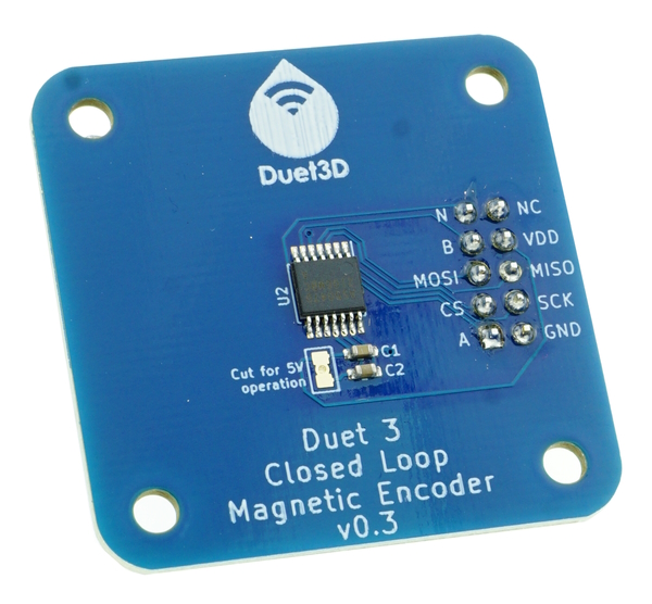
The Duet3D magnetic encoder senses motor position and rotation using a hall effect sensor to detect the rotation of a diametrically-magnetised disc magnet attached to the motor shaft at the rear of the motor.
¶ Features
¶ Specification
- 14 Bit On-Axis Magnetic Rotary Sensor: AS5047D or AS5047P1
- Maximum sensor RPM supported 14500 2
- Supplied with a 4mm thick, 6mm diameter magnet
- SPI output for communication with a Duet 3 Expansion 1HCL controller (supplied with a 150mm ribbon cable for this purpose)
- 3.3V operation - compatible with the Duet 3 Expansion 1HCL controller (Can be modified for 5V operation for other applications.
- Maximum ambient temperature: 85°C
1 AS5047D/P sensors are interchangeable in this application.
2 Max system RPM possible depends on the Duet 3 Expansion 1HCL controller closed loop speed and the maximum motor RPM
¶ Limitations on use
- Keep away from strong external magnetic sources, as they may cause errors in sensor readings.
¶ Supported hardware
¶ Duet 3 hardware
The Duet 3 Magnetic Encoder is designed to be paired with a Duet 3 Expansion 1HCL controller.
¶ Compatible motors
NEMA17: All NEMA17 motors with an exposed rear shaft no more than 3.5mm below the back of the motor should be compatible. If the exposed rear shaft projects from the back of the motor then a mounting solution that holds the sensor ~1mm from the magnet mounted on the shaft will be required.
NEMA23 and other sizes: An adaptor plate/mounting system would be required to use the Duet 3 Magnetic Encoder with other motors.
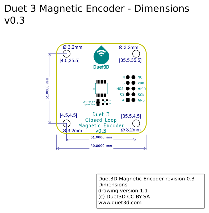
¶ Dimensions
¶ 3D Model
The STEP file is hosted here.
¶ Installation
¶ Required parts
| Qty | Item | Remarks |
|---|---|---|
| 1 | Magnetic Encoder PCB | Included |
| 1 | 6mm diameter x 4mm long diametrically-magnetised magnet | Included. A 6mm magnet was chosen because it fits even in recessed shaft NEMA 17 motors. |
| 4 | 0.5mm M3 nylon washer | Included |
| 4 | 1mm M3 nylon washer | Included |
| 4 | 2mm M3 nylon washer | Included |
| 4 | 3mm M3 nylon washer | Included |
| 1 | 150mm ribbon cable 10 way | Included |
| 1 | LOCTITE 648, 435, a cyanoacrylate adhesive or equivalent | Not provided. Select an adhesive that is tolerant of slight oil contamination potentially present at the back of the motor and is heat tolerant enough for your application. The magnet is not under significant load, but is exposed to the motor vibrations. |
| 1 | Printed jig for centring the magnet | Not provided, see below |
| 2 | M3 screws to mount PCB on rear of motor | Not provided. The length of bolt required depends on motor length, see step 3 below |
¶ Printed Jig
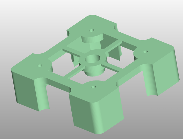
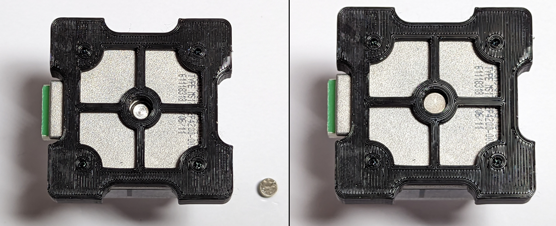
In order to ensure the magnet is centered on the motor shaft, a printed jig can assist with the magnet installation.
The STL and OpenSCAD design for the jig are available here
The jig can be printed using a reasonably tuned FDM 3d printer with a 0.4mm nozzle.
¶ Step 1 - Print, test fit jig and magnet
- Test fit the printed jig to the motor, and test that the magnet can move freely in the central alignment hole without significant lateral movement
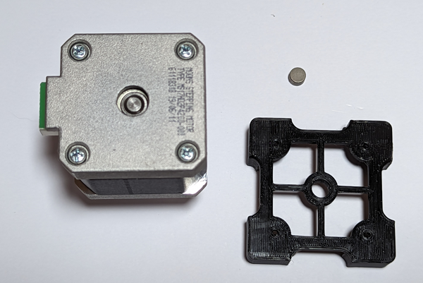
¶ Step 2 - Glue in magnet
- Apply adhesive to the magnet, glue to rear motor shaft and leave adhesive to cure.
- Follow the manufacturer's instructions for the adhesive regarding curing time, temperature and any pressure required.
¶ Notes on magnet placement
There are three main factors that affect the strength and linearity of the magnetic field that the sensor detects, listed below. These notes are based on the sensor manufacturer's application note here.
Off-axis magnet placement and encoder errors
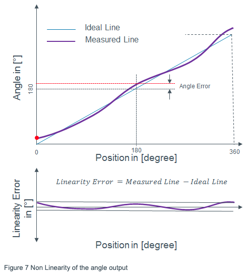
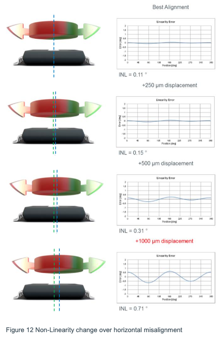
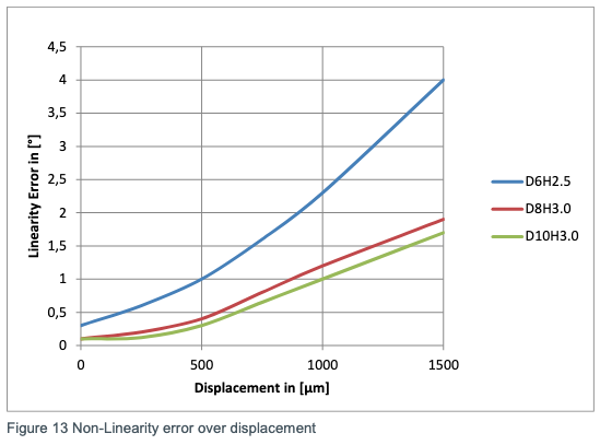
The linearity of the detected magnetic field changes with mechanical displacements in the x and y direction (ie if the magnet is off-centre). Ideally, the magnet should rotate over the sensor chip such that the centre of the magnet, the centre of rotation, and the centre of the chip, are in one vertical line. The better the magnet is centred on the shaft, the lower the encoder errors will be. See section 1.5 and 1.6 of the application note.The integral non linearity (INL) is one of the important parameters for position sensors in general. This parameter specifies the effective angle error from the total system. The magnetic position sensor system performance is mainly dependent on magnetic and mechanical constraints. Electrical errors from position sensor IC play mostly a minor role.
The non-linearity parameter represents the difference between the measured and the ideal line. Offset angle components are not considered in this calculation. (Best-Line-Fit method).
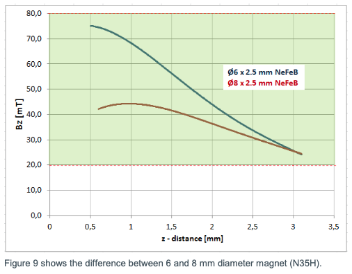
A slightly wider diameter magnet will work slightly better for the same flux density, up to about 10mm. Duet3D chose a 6mm magnet because that fits even in recessed shaft NEMA 17 motors.
Distance from magnet to sensor
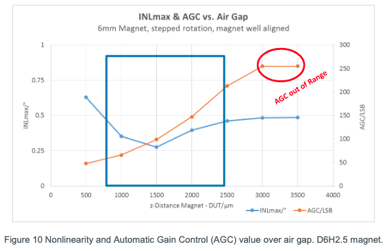
The vertical distance from the sensor surface to the magnet surface (air gap) is an important parameter for the linearity of the system. The strength of the magnetic field reduces as the distance between magnet and sensor increases. For the supplied 6mm magnet, there should be an air gap of no more than 1mm between magnet and sensor. See section 1.6.1 of the application note.Figure 10 shows the tendency of the non-linearity choosing different air gaps. In addition the automatic gain control (AGC) value is shown. This value is increasing with increasing distance, reaching the limit at larger air gaps. The magnetic position sensor is still operating in this area, but with increased noise output.
Magnets and temperature
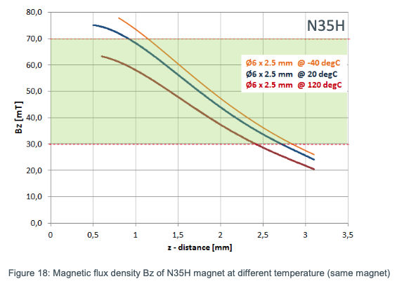
The temperature will also affect the magnetic field, with higher temperatures reducing the strength of the magentic field. Check the maximum temperature the motor will get to and check the specification of the magnet. Duet3D supply high temperature magnets for mounting on the motor shaft, which should not be needed in most cases, but could help if the motor is running hot. See section 2.6 of the application note.¶ Step 3 - Mount Magnetic Encoder PCB on motor
- Remove two of the four m3 threaded bolts from the motor from opposing corners.
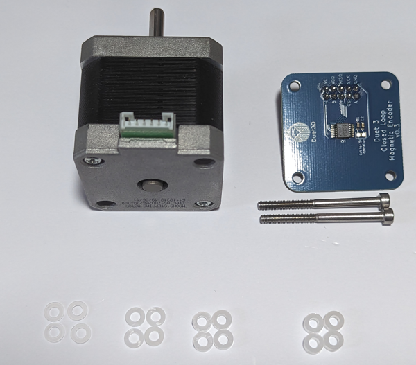
- Fit the magnetic encoder board to the back of the motor, using the nylon washers as spacers so the encoder chip is ~1mm from the magnet.
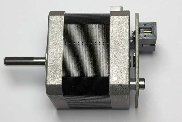
¶ Step 4 - Connect to Duet 3 Expansion 1HCL
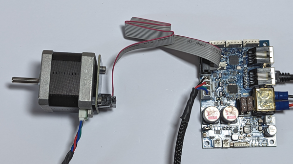
- Connect using the ribbon cable and a stepper motor cable to the 1HCL.
- Move on to configuration.
¶ Configuration
This should be read in conjunction with the Duet 3 Expansion 1HCL documentation
¶ Config.g changes
M569.1 is used to configure the closed loop driver.
The T parameter specifies that the encoder used is the Duet 3 Magnetic encoder
Here's an sample excerpt from a config.g file for RRF 3.5 to drive the X motors from 1HCL board configured at CAN addresses 50, with a Duet 3 Magnetic encoder.
M569.1 P50.0 T3 E1:2 R100 I0 D0 ; Configure the Duet 3 Expansion 1HCL board at CAN address 50 with a Duet 3 magnetic encoder, warn if 1 fullstep threshold exceeded, error if 2 full steps threshold exceeded.
M569 P50.0 D4 S1 ; Configure the motor on the Duet 3 Expansion 1HCL controller at can address 50 as being in closed-loop drive mode (D4) and not reversed (S1)
M584 X50.0; set X drivers
Note the initial PID values shown will need to be tuned to the particular motor.
¶ Magnetic Encoder Tuning.
The M569.6 command is used to tune the motor and encoder pair, e.g.
M569.6 P51.0 V2 ; conduct magnetic encoder calibration on move on closed loop driver on Duet 3 Expansion 1HCL board with magnetic encoder at address 50.
This can be checked with V3 and cleared with V4, see Runtime Tuning.
It must be run once for a new 1HCL, motor, magnet or magnetic encoder board. The values are stored in flash memory, so it does not need to be run again unless the system changes (i.e. you replace the Duet 3 Expansion 1HCL controller, motor, magnet or magnet encoder board, or you remove and re-fit the magnetic encoder board or the magnet).
Note: this initial tuning must be run with the motor unloaded for best results
¶ Revision history
- Changed the ribbon cable header to 2x5 to match the SPI encoder input header on the 1HC
- Routed the A/B/N signals to he header (currently not used)
Initial prototype
