¶ Scope
This document is relevant to: Duet 2, Duet 3
Firmware versions: RepRapFirmware 1.20 and later
¶ Introduction
DHT sensors are low-cost digital temperature and humidity sensors. They use a capacitive humidity sensor and a thermistor to measure the surrounding air, and transmit a digital signal on the data pin to the host, so no analog input pins are needed.
RepRapFirmware from v1.20 supports DHT11, DHT21 and DHT22 sensors.
RepRapFirmware from v3.4 drops support for DHT11 sensors
RepRapFirmware from v3.5 adds support for BME280 sensors
RepRapFirmware from v3.7 adds support for BME680, BME688 and BME690 sensors
¶ General recommendations
- The BME280 or BME680/688/690 is recommended. DHT22 is supported, but is becoming harder to find. DHT21 is also supported, but is less accurate. DHT11 support has been removed from current firmware.
- DHT22/21/11 connect using 3 wires. As well as +3.3V and ground, the DHT sensor needs a combined input-output line. This is usually connected to one of the SPI CS lines on the Temperature Daughterboard connector, or one of the IOx.OUT pins.
- BME280 and BME680/688/690 connect using 6 wires, and connects to pins on the Temperature Daughterboard connector.
- In RRF 3, the humidity and pressure (BME280/BME68x only) channels of the same sensor are configured as piggyback sensors off the main sensor. The BME680/688/690 also provides a gas resistance channel.
¶ Choosing a DHT sensor
Which sensor you use will depend on your application. DHT sensors can be bought as a bare sensor, on a PCB, or as a wired version in a large plastic case.
Relatively low-cost, the BME280 from Bosch usually comes packaged on a small breakout board, and can measure humidity, temperature and barometric pressure.
- Humidity: ±3% accuracy
- Temperature: -40 to 85°C temperature readings ±1°C accuracy
- Pressure: 300 to 1100 hPa with ±1 hPa absolute accuracy
- Sensing period: 1 Hz sampling rate (once every second)
- Dimensions: vary
¶ Notes
- BME280 sensors are only supported on Duet 3, not Duet 2.
- BME280 sensors are only supported in RepRapFirmware 3.5 and later.
- RepRapFirmware currently supports BME280 sensors using SPI, not I2C. Breakout boards need to have the appropriate pins accessible. For example, this board from Adafruit or this one from Sparkfun should work fine. Many boards available have only 4 pins; these are I2C only, and are not supported.
- The BMP280 (temperature and barometric pressure only) is not supported.
The BME680, BME688 and BME690 are environmental sensors from Bosch that measure temperature, humidity, barometric pressure and gas resistance (air quality). They are more capable than the BME280 due to the addition of the gas sensor.
- Humidity: ±3% accuracy
- Temperature: -40 to 85°C temperature readings ±1°C accuracy
- Pressure: 300 to 1100 hPa with ±0.6 hPa accuracy
- Gas resistance: indicates air quality / VOC concentration (Ω)
- Sensing period: 1 Hz sampling rate (once every second)
- Dimensions: vary
¶ Notes
- BME68x sensors are only supported on Duet 3, not Duet 2.
- BME68x sensors are only supported in RepRapFirmware 3.7 and later.
- RepRapFirmware supports BME68x sensors using SPI only, not I2C. Wiring is the same as for the BME280.
- The gas resistance output reflects air quality: higher resistance means cleaner air. In typical clean indoor air expect 50–200 kΩ once the sensor has warmed up. The sensor requires a burn-in period of several minutes before gas readings stabilise.
- The gas heater runs at 320°C for 150 ms per measurement cycle.
Recommended. More precise, more accurate and works in a bigger range of temperature/humidity. Larger and more expensive than DHT11, and only updates once every 2 seconds.
- Humidity: 0-100% humidity readings with 2-5% accuracy
- Temperature: -40 to 80°C temperature readings ±0.5°C accuracy
- Sensing period: 0.5 Hz sampling rate (once every 2 seconds)
- Dimensions: 32mm x 15mm x 7mm
NOTE: Cloned DHT22 sensors. One customers reported problems getting a DHT22 sensor working with RRF, even though the sensor worked with an Arduino. The issue was investigated and it was discovered that the sensor did not conform to the specification of the DHT22 sensor as on the datasheet provided by Adafruit.
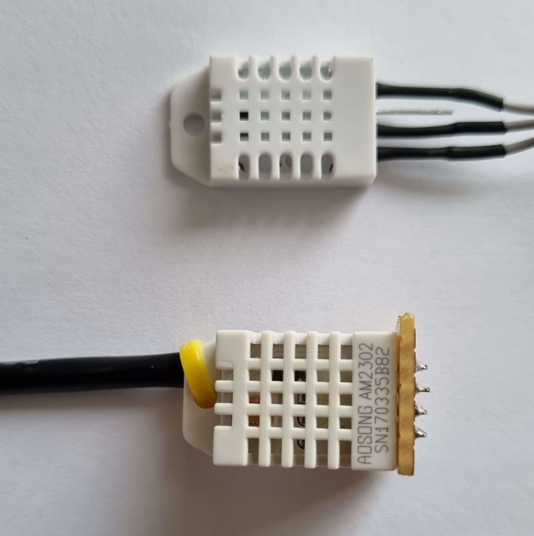
The customer's sensor is pictured above (top in picture) and a sensor that works (below in picture). The working sensor carries the identification "AOSONG AM2302" whereas the customer's sensor carries no markings at all. The vast majority of images of DHT22 sensors on Amazon and eBay do carry the part identification, but a few do not and look like the sensor received from the customer. Therefore, if you need a DHT22 sensor for your Duet-based system, please make sure to buy a genuine one bearing the correct part identification. See this forum thread for more information.
Usually packaged in a large case, with three wires. Similar specification to DHT22, but less accurate.
- Humidity: 0-100% humidity readings with 3-5% accuracy
- Temperature: -40 to 80°C temperature readings ±1°C accuracy
- Sensing period: 0.5 Hz sampling rate (once every 2 seconds)
- Dimensions: 59mm x 27mm x 13.5mm
Usually cheapest, with limited range for temperature and humidity, but small and updates every second. Not supported in RRF 3.4. or later.
- Humidity: 20-80% humidity readings with 5% accuracy
- Temperature: 0-50°C temperature readings ±2°C accuracy
- Sensing period: 1 Hz sampling rate (once every second)
- Dimensions: 22.5mm x 12mm x 5.5mm
¶ Connecting a DHT sensor
¶ Cable recommendations
BME280 sensors should be less sensitive to interference than DHT sensors, but the cable should still be kept away from stepper motor cables.
¶ Wiring
Using the Temperature Daughterboard connector (TEMP_DB), connect the SDI (may be labelled as SDA), SDO and SCK (SCL) pins of the BME280 to MOSI, MISO and SCK respectively. Also connect CS (may be labelled CSB) to your chosen spi.cs pin, 3.3V power and ground.
BME680/688/690 sensors use identical wiring to the BME280.
| Duet Temp Daughterboard connector | BME280 | |||
|---|---|---|---|---|
| Pin # | Pin name | Pin name / alternate name | ||
| 6HC, 3HC | 6XD | Mini 5+ | ||
| 1 | spi.cs1 | spi.cs2 | CS / CSB | |
| 2 | GND | GND | ||
| 3 | spi.cs0 | spi.cs1 | (alternative for CS / CSB) | |
| 4 | SPIO_SCK | SCK / SCL | ||
| 5 | SPIO_MOSI | SDI / SDA | ||
| 6 | SPIO_MISO | SDO | ||
| 7 | spi.cs2 | spi.cs3 | not connected | (alternative for CS / CSB) |
| 8 | +3.3V | VCC | ||
| 9 | spi.cs3 | spi.cs4 | not connected | (alternative for CS / CSB) |
| 10 | not connected | - | ||
¶ Cable recommendations
Connect the sensor to +3.3V and GND. Do not use 5V unless you use a bidirectional level shifter between the Duet and the DHT22.
DHT sensors use the one-wire bus, which is sensitive to noise, so if you use unshielded cable it is very likely to pick up interference from any stepper motor cables that it runs close to. We recommend using shielded cable (stereo microphone cable should work), using the shield for the ground connection.
Bare DHT sensors usually come with a pullup resistor of between 4k7 and 10k ohms. DHT sensors on a PCB, or encased and pre-wired, usually have the pullup resistor already fitted on the PCB. The pullup resistor goes between the signal line and 3.3V.
Cable capacitance should not exceed about 2000pF. Using a lower value resistor will allow longer cable runs, eg a 2k2 ohm, but be more susceptible to noise. Shielded cables normally specify the capacitance/meter, so you should be able to work out the highest value pullup resistor you can use for a specific length and type of cable. If a higher pullup resistor is used then the max cable length is reduced. In testing, dc42 uses a 10K pullup resistor and 400mm of cable.
¶ Wiring
Connect the DHT I/O line to either one of the SPI CS lines on the Temperature Daughterboard connector, or one of the IOx.OUT pins. Both of these connectors also provides +3.3V and ground.
Connect the DHT I/O line to both IOx.IN and the IOx.OUT pin of an IO connector. The IO connector also provides +3.3V and ground. Using the Temperature Daughterboard connector is NOT supported. RepRapFirmware 3.3beta1 or later is required.
Connect the DHT I/O line to one of the SPI CS lines on the temperature daughterboard connector. This connector also provides +3.3V and ground. For systems running RRF 3 with no DueX expansion connected, some of the expansion connector pins could be used instead, for example the E2 to E6 endstop pins (E0 and E1 on the Duet cannot be used).
¶ Configuring a DHT sensor
In RRF 3, M308 is used to define the BME280 sensor. Use the following parameters:
- Sn Sensor number.
- P"pin_name" See section above for pins to use with each Duet version.
- Y"sensor_type" "bme280", "bme-pressure", "bme-humidity" (RRF3.5 and later on Duet 3 only)
- A"name" Sensor name (optional), displayed in the web interface
The BME280 has a primary output for temperature, secondary output for pressure, and third for the humidity values. A primary sensor is created for temperature, eg S11, and "bme-pressure" will be attached to this sensor as a secondary output by using its full sensor number (including the leading S) and the output's index separated by a dot, eg S11.1. "bme-humidity" is attached in the same way as the third output.
Example:
m308 s11 y"bme280" p"spi.cs1" a"Ambient temp"
m308 s12 y"bme-pressure" p"s11.1" a"Pressure[hPa]"
m308 s13 y"bme-humidity" p"s11.2" a"Humidity[%]"
In RRF 3.7, M308 is used to define the BME68x sensor. Use the following parameters:
- Sn Sensor number.
- P"pin_name" See section above for pins to use with each Duet version.
- Y"sensor_type" "bme68x", "bme68x-pressure", "bme68x-humidity", "bme68x-gas" (RRF3.7 and later on Duet 3 only)
- A"name" Sensor name (optional), displayed in the web interface
The BME68x has four outputs: temperature (primary), pressure, humidity and gas resistance. The pressure, humidity and gas resistance outputs are attached as secondary outputs using the primary sensor number with a dot-indexed suffix.
Example:
M308 S11 Y"bme68x" P"spi.cs0" A"Ambient temp"
M308 S12 Y"bme68x-pressure" P"S11.1" A"Pressure[hPa]"
M308 S13 Y"bme68x-humidity" P"S11.2" A"Humidity[%]"
M308 S14 Y"bme68x-gas" P"S11.3" A"Gas resistance[Ohm]"
¶ RepRapFirmware 3.x
In RRF 3, M308 is used to define the DHT sensor. Use the following parameters:
- Sn Sensor number.
- P"pin_name" See section above for pins to use with each Duet version.
- Y"sensor_type" "dht11" (RRF 3.3 and earlier), "dht21", "dht22", "dht-humidity"
- A"name" Sensor name (optional), displayed in the web interface
All DHT variants have a primary output for temperature and a secondary output that delivers the humidity values. "dht-humidity" will be attached to an existing DHT sensor's secondary output by using its full sensor number (including the leading S) and the output's index separated by a dot.
Example:
;DHT Sensor on Temperature Daughterboard SPI CS1 pin
M308 S10 P"0.spi.cs1" Y"dht22" A"Filament Temp" ; define DHT22 temperature sensor
M308 S11 P"S10.1" Y"dht-humidity" A"Filament Hum[%]" ; Attach DHT22 humidity sensor to secondary output of temperature sensor
On Duet 3 Mini 5+, as you connect the DHT data line to both IOx.out and IOx. in, you need to specify both pins in the M308 command.
;DHT Sensor on IO4 on Duet 3 Mini 5+
M308 S10 P"io4.out+io4.in" Y"dht22" A"Chbr Temp"
M308 S11 P"S10.1" Y"dht-humidity" A"Chbr Hum[%]"
¶ RepRapFirmware 2.x
In RRF 2 and earlier, M305 is used to define the DHT sensor. In RRF 2, every temperature sensor belongs to a heater. For sensors with no controllable heater (e.g. DHT sensors) you have to create a "virtual heater" in order to be able to use the sensor. Use the following parameters:
- Pnnn Heater number (0, 1, 2...) or virtual heater number (100, 101, 102...)
- S"name" Heater name (optional). Named virtual heaters are shown in Duet Web Control; anonymous virtual heaters are not.
- Xnnn Heater ADC channel, or thermocouple or PT100 adapter channel; defaults to the same value as the P parameter
- Tnnn (for thermistor sensors) The thermistor resistance at 25oC
The X parameter tells the firmware which temperature sensor channel to use. For DHT sensors, set as follows:
- Channels 400, 401... are DHTxx temperature channels. The DATA line of the DHTxx must be connected to one of pins CS1, CS2... on the SPI bus.
- Specify the sensor type (11 for DHT11, 21 for DHT21 or 22 for DHT22) via the T-parameter.
- Channels 450, 451... are as 400, 401... but specify the corresponding humidity sensor of the DHTxx
Example:
;DHT Sensor on Temperature Daughterboard SPI CS1 pin
M305 P103 X400 T22 S"DHT Temperature"
M305 P104 X450 T22 S"DHT Humidity [%]"
¶ Displaying DHT data
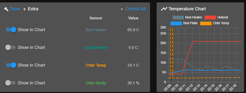
View the DHT sensor data in DWC, in the main Printer Status section, in the 'Extra' view of the 'Tools' section (see Duet Web Control manual).