¶ Introduction
RepRapFirmware allows you to define external 'triggers' (such as a button press) that will run an associated system macro. This could be for an emergency stop, but can be used for many other purposes, as the GCode commands that are run are held in a macro file for each trigger.
Below are two examples:
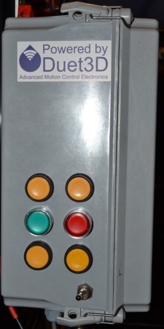
- User Clinton Thomas builds a control panel, with a number of buttons which control various actions. This originally appeared on the Duet Dozuki wiki, using a Duet 2 and RRF 2.x
- User Nick Lindenmuth builds a water flow sensor failsafe, to add a flow sensor to trigger a reset using an arduino nano. This originally appeared on the Duet Dozuki wiki, using a Duet 2 and RRF 2.x
These examples have been updated for Duet3 and RRF 3.x.
¶ Control Panel
¶ Required hardware
- Some kind of push button or switch (eg Idec and Allen-Bradley brand push buttons with Normally Open contact blocks)
- Molex KK (for endstop/IO connectors) or Dupont connectors (Duet 2 expansion header)
- Wire
¶ Wiring
Buttons for pause, ATX on, disable steppers, home all and reset were required.
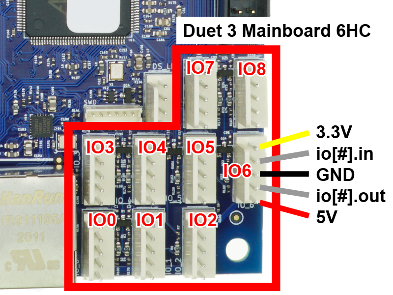
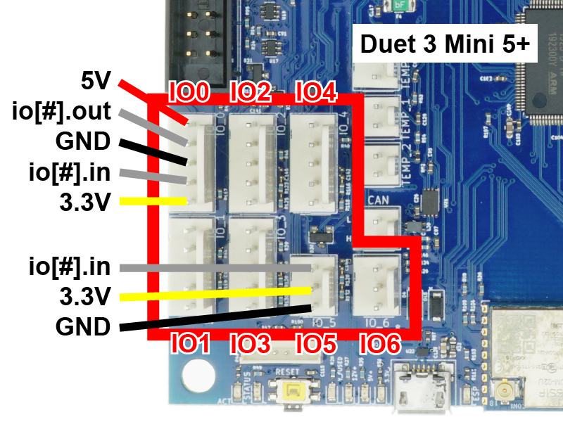
Wire the switch in the same way as an endstop. Connect one side of the switch to the GND pin of your chosen IO_x connector (or the negative coming from your power supply), and the other to the IN pin of the IO_x connector.
It is worth noting that IO output pins can be used as inputs, but are only 3.3V tolerant.
For a reset button, on Duet 3 mainboard 6HC there is a 'reset' header near the USB port, with reset and GND pins. On the Duet 3 Mini 5+, the reset pin is on the 12864_EXP2 header, pin 3.
In the example, the following pins could be used :
- Reset - reset pin on header
- Pause - io1.in
- ATX on - io1.out
- Home all - io2.in
- Pin 26 - io2.out
- (spare) = io5.in
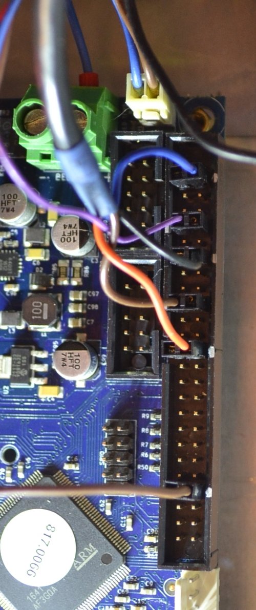
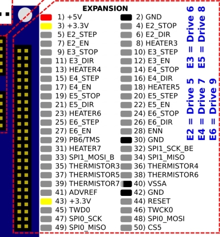
Connect one side of the switch to a GND pin (or the negative coming from your power supply), and the other to the chosen STP/IN/E#_STOP pin. In the example below, the E#_STOP pins of the expansion header are used.
In the image above, 2P Dupont connectors were used, but only one of the pins has a wire going to it. This is because 1P connectors kept falling off so I put a wire in one side of a 2P connector with just an empty pin in the other side.
In the example, the following pins are used:
- Pin 4 / E2_STOP = pause
- Pin 9 / E3_STOP = ATX on
- Pin 14 / E4_STOP = home all
- Pin 19 / E5_STOP = disable steppers
- Pin 26 / E6_STOP = spare
- Pin 44 / RESET = reset
Pin 44 forces a reset when shorted to ground, no additional configuration is needed.
¶ Firmware configuration
In RRF 3.x, triggers pins are configured with M950, and are configured in the firmware using M581. The parameters for RRF 3.01 and later (see GCode dictionary for earlier versions) are:
- P Specify one or more input pin numbers that you created using M950 with the J parameter, or -1 to delete the trigger
- Tnn Logical trigger number to associate the input(s) with, from zero up to a firmware-specific maximum
- S Whether trigger occurs on an inactive-to-active edge of that input (S1, default), active-to-inactive edge (S0), or ignores that input (S-1).
- R Condition: whether to trigger at any time (R0, default), only when printing a file from SD card (R1), or only when not printing a file from SD card (R2, supported in RRF 3.2 and later). R-1 temporarily disables the trigger.
- X, Y, Z or any other axis letter: axis or axes whose endstop switches are to cause the trigger
Note that:
- Trigger number 0 causes an emergency stop as if M112 had been received. Trigger number 1 causes the print to be paused as if M25 had been received. Any trigger number # greater than 1 causes the macro file sys/trigger#.g to be executed. Polling for further trigger conditions is suspended until the trigger macro file has been completed. RepRapFirmware does not wait for all queued moves to be completed before executing the macro, so you may wish to use the M400 command at the start of your macro file. If several triggers are pending, the one with the lowest trigger number takes priority.
- When M581 is executed, if the T parameter is present but the other parameters are omitted, the trigger inputs and edge polarities for that trigger number are reported. Otherwise, the specified inputs and their polarities are added to the conditions that cause that trigger.
- A maximum of 32 triggers can be configured on Duet 3, a maximum of 16 on Duet 2.
- Warning: if executed during a job, and more than one line long the GCode within the trigger file may be executed between later commands from the job. Bounding the trigger file with M25 and M24 may help, but this will cause warnings if the trigger happens outside of a job. The use of M25/M24 will cause the execution of pause and resume system macros.
M950 is used to define each pin, then M581 configures the trigger. In order to get buttons for pause, home, ATX on, and disable steppers, the following were added to config.g:
Duet 3
; Input/Output
M950 J1 C"!io1.in"  ; Input 1 uses io1.in pin, inverted
M581 P1 S0 T1 R1    ; Pause - built-in, no trigger.g needed

M950 J2 C"!io1.out" ; Input 2 uses io1.out pin, inverted
M581 P2 S0 T2 R0    ; ATX On - trigger2.g

M950 J3 C"!io2.in"  ; Input 3 uses io2.in pin, inverted
M581 P3 S0 T3 R0    ; Home All - trigger3.g

M950 J4 C"!io2.out" ; Input 4 uses io2.out pin, inverted
M581 P4 S0 T4 R0    ; Disable Steppers - trigger4.g
Duet 2
; Input/Output
M950 J1 C"!^e2stop" ; Input 1 uses e2stop pin, inverted, pullup enabled
M581 P1 S0 T1 R1    ; Pause - built-in, no trigger.g needed

M950 J2 C"!^e3stop" ; Input 2 uses e3stop pin, inverted, pullup enabled
M581 P2 S0 T2 R0    ; ATX On - trigger2.g

M950 J3 C"!^e4stop" ; Input 3 uses e4stop pin, inverted, pullup enabled
M581 P3 S0 T3 R0    ; Home All - trigger3.g

M950 J4 C"!^e5stop" ; Input 4 uses e5stop pin, inverted, pullup enabled
M581 P4 S0 T4 R0    ; Disable Steppers - trigger4.g
In RRF 2.x, only M581 is required to set up a trigger. Triggers can only be connected to endstops (X, Y, Z, E#).
In order to get buttons for pause, home, ATX on, and disable steppers, the following were added to config.g:
; Input/Output
M581 E2 S1 T1 C1         ; Pause - PIN4/E2_STOP
M581 E3 S1 T2 C0         ; ATX On - PIN9/E3_STOP - trigger2.g
M581 E4 S1 T3 C0         ; Home All - PIN14/E4_STOP - trigger3.g
M581 E5 S1 T4 C0         ; Disable Steppers - PIN19/E5_STOP - trigger4.g
¶ Triggers
Finally, add macro trigger files to the /sys folder. These are just text files containing the respective commands saved as trigger#.gcode.
;trigger2.g
M80            ; ATX ON
;trigger3.g
M400            ; Finish current moves
G28            ; Home all axes
;trigger4.g
M400            ; Finish Current Moves
M18            ; Disable Steppers
¶ Water flow sensor failsafe
A spare IO header (Duet 3) or endstop (Duet 2) can be used to trigger a full system reset. Here, an arduino is used to convert the flow sensor signal into an on or off state, for flow or no flow.
¶ Required hardware
- 1 × Arduino Nano
- 1 × uxcell Hall Effect Flow Sensor SEN-HW06K
¶ Programming the arduino
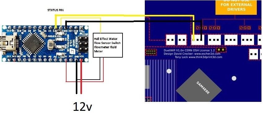
- Upload this code to your arduino nano. Refer to the diagram above on how everything is connected. The hardest part is crimping the pins for the endstop connector.
- Here is a simple case I made for the nano.
¶ Wiring
-
Duet 3: Connect Arduino Nano 'status' pin (D3) to the IN pin of your chosen IO connector (eg io1.in), and the Arduino 'GND' pin to the 'GND' pin of the IO connector.
-
Duet 2: See image below. Connect Arduino Nano 'status' pin (D3) to STP/IN pin of your chosen endstop connector, and the Arduino 'GND' pin to the 'GND' pin of the endstop connector. These are the outer 2 pins of the 3-pin connector.
NOTE:
-
Duet 2 WiFi/Ethernet boards prior to version 1.04 cannot tolerate voltages on endstop pins of more than 3.3V. Add 4 diodes in series to drop the voltage to 3 ish volts.
-
All other Duets (Duet 3, Duet 2 WiFi/Ethernet v1.04 and later, Duet 2 Maestro) tolerate voltages of at least 5V on IO/endstop connectors.
¶ Configuration
- Now we have to tell the duet what to do with the on/off signal using the M581 command. Insert the following, as approriate into your config file:
Duet 3, RRF 3
M950 J1 C"io1.in"  ; Arduino is connected to io1.in pin
M581 P1 S1 T0 C0

Duet 2, RRF 3
M950 J1 C"^e1stop" ; Arduino is connected to e1stop pin, pullup enabled
M581 P1 S1 T0 C0

Duet 2, RRF 2
M581 E1 S1 T0 C0 ; Arduino is connected to endstop E1
And thats it!!! You can test by unpluging your pump or pinching a line, it should reset within a few seconds.
