¶ Introduction
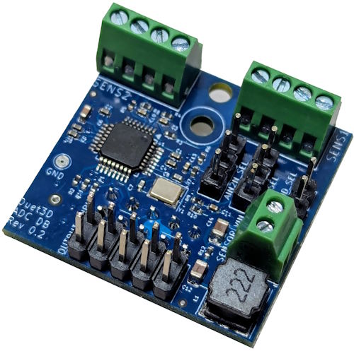
The Duet 3 ADC daughterboard provides two high resolution analog-to-digital converter (ADC) channels. These are useful for reading analog signals such as pressure feedback from external hardware. This daughterboard is one of a number of SPI connected sensor boards that also include the PT100 and Thermocouple daughterboards.
¶ Features
¶ Supported hardware
Each daughterboard supports 2 channels, i.e. two separate analog inputs per daughterboard. Duet mainboards and expansion boards support two, one or zero daughterboards. Refer to the table below.
Note the ADC Daughterboard is not supported on Duet 2 hardware.
| Duet board | Number of boards supported | Notes |
|---|---|---|
| Duet 3 Mainboard 6HC | 2 | stacked |
| Duet 3 Mainboard 6XD | 2 | stacked |
| Duet 3 Mini 5+ | 1* | Direct connection fouls the TEMP0 connector so a short ribbon cable <100mm (not supplied) is required to connect the board |
| Duet 3 Expansion 3HC | 2 | stacked |
| Duet 3 Expansion 1HCL | 1 | v2.0 only. Direct connection fouls the DRIVER connector so a short ribbon cable <100mm (not supplied) is required to connect the board |
| Duet 3 Toolboard 1LC | Not supported | |
| Duet 3 Roto Toolboard | Not supported | |
| Duet 3 Expansion 1XD | Not supported | |
*Note,the Mini 5+ Ethernet v1.03 supports two SPI DB boards stacked, v1.02a and earlier support 1
Mainboards and expansion boards that support only one daughterboard can have either an ADC, Thermocouple or PT100 temperature sensor daughterboard connected, but not two. Those that support two SPI daughterboards can have different daughterboards connected.
¶ Features
¶ Hardware specification
| ADC IC | ADS131A02. 24-bit 128-kSPS 2-channel simultaneous-sampling delta-sigma ADC |
| Analog voltage input range | |
| Unipolar | 0 to +10V |
| Bipolar | -5 to +5V |
¶ Operating limits
| Power pass through voltage | 12-36V |
| Power pass through max current | 200mA |
| Data signalling voltage | 3.3V |
| Maximum ambient temperature | 80°C |
| Absolute maximum board temperature | 85°C |
¶ Firmware notes
- Compatible RepRapFirmware versions: RRF 3.6 or later
¶ Physical properties
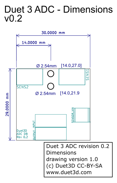
¶ Dimensions

¶ 3D model
The STEP file for the Duet 3 ADC daughterboard is shared on the Duet3D GitHub here.
¶ Mounting
The ADC daughterboard connects to the SPI_DB connector on the Duet 3 mainboard or expansion board (this was called TEMP_DB on earlier versions of some Duet 3 controllers). Make sure the daughterboard is orientated correctly before connecting, see the wiring diagram for your mainboard.
We supply a plastic pillar with each daughterboard, to secure the daughterboard to the Duet or to the daughterboard below it. If the prongs of the pillar won't go into the hole in the circuit board easily, gently squeeze the prongs together with a pair of pliers first.
On mainboards that support more than one temperature daughterboard, the second daughterboard is connected by stacking it on top of the first.
- Fit the plastic pillar on the underside of the daughter board in the hole closest to the edge of the board.
- Ensure that any jumper pins on the main board that will be covered by the daughter board have jumpers fitted where required.
- Plug the board on to the SPI daughter board header pins of the main board. The plastic pillar should line up with the hole in the main board and can be pushed into place.
- Check that the bottom of the daughter board does not short against any header pins or jumpers below it.
- You can optionally fit another Duet3D SPI daughter board on top of this one.
- It is also possible to fit this daughter board on top of another Duet3D daughter board.
¶ Physical connections
¶ Wiring

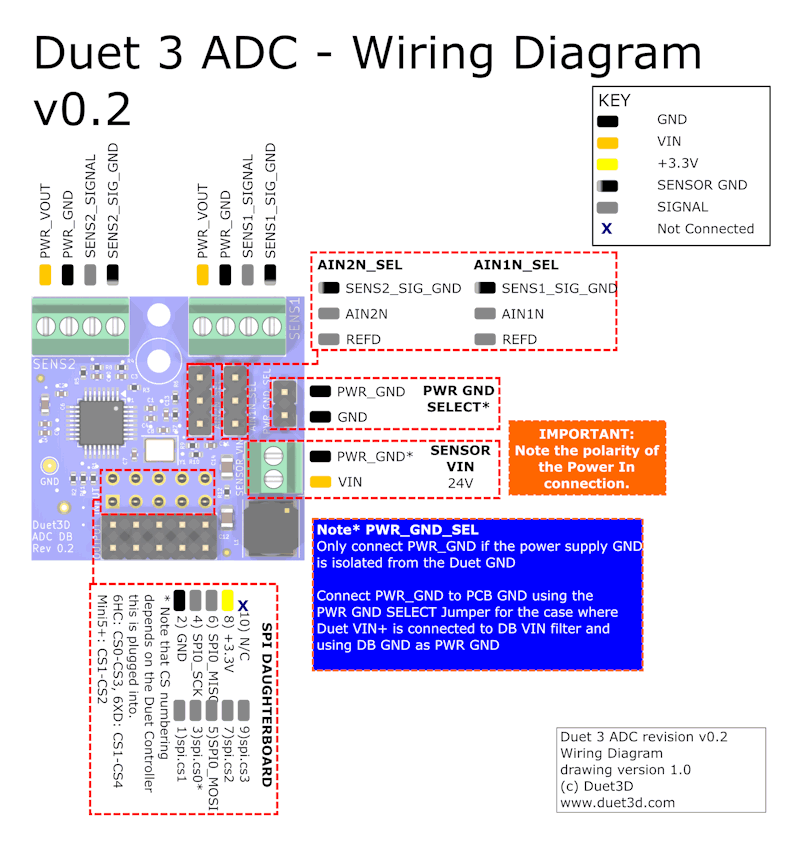
¶ Description of Connections
Duet 3 ADC daughterboard has the following connectors:
| Connector | Label | Function |
|---|---|---|
| 4-pin Screw Terminal x2 | SENS1, SENS2 | Analog input connections for signal and power |
| 2-pin Screw Terminal | SENSOR VIN | Power for the connected analog device(s) |
| 2x5 Pin IDC | INPUT | Connection to SPI DB header on Duet 3 controller |
| 2x5 Pin IDC | OUTPUT | Connection to allow second compatible daughterboard to be stacked |
| Function | Connector | Pin name | Notes |
|---|---|---|---|
| Analog Inputs | SENS1 | PWR_VOUT 1 | Power supply for the analog device. Supplied from VIN connector via filtering circuit |
| PWR_GND 1 | GND for the power to the analog device | ||
| SENS1_SIGNAL | Channel 0 Analog signal input | ||
| SENS1_SIG_GND | Channel 0 Analog ground input | ||
| SENS2 | PWR_VOUT 1 | Power supply for the analog device. Supplied from VIN connector via filtering circuit | |
| PWR_GND 1 | GND for the power to the analog device | ||
| SENS2_SIGNAL | Channel 1 Analog signal input | ||
| SENS2_SIG_GND | Channel 1 Analog ground input | ||
| Power Passthough1 | SENSOR VIN | VIN | 12-36V , 200mA max voltage supply for powering the connected analog device(s) |
| PWR_GND | ground supply for external power supply if the Duet ground is not used, see the Power Pass Though section below |
Notes:
1 Using the power and ground pass through the ADC board is optional, see Power Pass Through section below
¶ Power Pass Through
The ADC daughterboard provides a filtered power pass though with appropriate ground selection options to allow both the signal and power for an analog device to be connected. This is advantageous because:
- All the wiring can terminate at the same point
- A single power supply can be used for both (assuming compatible voltages)
- Power supply noise can be minimised.
- Ground loops can be avoided
Even if a separate supply is required for the sensors than for the Duet (for example the Duet is running at 48V and the sensors need 30V) it is generally still a good option to use the power pass through, with the ground configured as below.
¶ Using the Duet power supply to power the sensor(s)
Connect either +VIN or +12V power from the Duet to the VIN terminal of the 2-pin connector on the daughter board (this is the left-hand terminal when looking into the 2-pin connector). You do not need to connect the right-hand terminal. Fit a jumper to the PWR_GND_SEL pins. This will connect the Power Ground terminals on the input terminal blocks to Duet ground.
¶ Using a separate power supply to power the sensor(s)
Connect a suitable power supply to the 2-pin connector, positive to the left hand terminal looking into the connector. Do not fit a jumper to the PWR_GND_SEL pins
¶ Connecting sensors
Each 4-way terminal block provides the following connections, from left to right looking into the terminal block: Signal Ground, Signal, Power Ground, +Power. It is assumed that signal ground and power ground are connected together in the sensor. For best accuracy, do not swap the signal and power grounds.
If the sensor does not provide separate Signal Ground and Power Ground connections, connect sensor ground to both Signal Ground and Power Ground on the terminal block.
If the second input is not used, connect the Signal, Signal Ground and Power Ground pins of that connector together. Do not connect the PWR_VOUT pin to any of the other pins.
¶ Selecting ADC ground reference inputs
Each ADC has an associated 3-pin header to select how the ADC reference input for that channel is connected. Jumpers must always be fitted to each of these headers in one of the two possible positions:
-
If the jumper is fitted in the position closest to the SENS1 terminal block, between the SENSn_SIG_GND and AINnN pin, then the signal ground connection of that sensor is used as the reference. This provides a unipolar reading between 0V and 10V.
-
If the jumper is fitted in the other position, between the AINnN pin and REFD, then a voltage equivalent to approximately 5V at the sensor input is used as the reference. This provides a bipolar reading between -5V and +5V, with the possibility of doubling the resolution.
¶ Firmware configuration
The daughter board is supported by firmware 3.6.0-beta.3 and later for Duet 3 main boards, 3HC and 1HCL expansion boards
¶ Configuring the first channel
Connected to the terminal block labelled SENS1 use a M308 command with the following parameters:
- Sensor number (S): as required
- Sensor type (Y) "ads131.chan0.u" or "ads131.chan0.b" depending on whether unipolar or bipolar operation is required
- Port name (P) "spi.cs0" if using a 6HC main board, "spi.cs1" for other main boards; except that if this daughter board is fitted on top of another Duet3D daughter board then add 2 to the cs number. (note you need to prepend the expansion board CAN address if the sensor is on an expansion board)
- Zero reading (B): the reading required when the ADC reading is at minimum (typically with 0V output from the sensor). Defaults to 0 if not provided.
- Full scale reading (C): the reading required when the ADC reading is at maximum (typically with 10V output from the sensor). Defaults to 100 if not provided.
Examples:
M308 S10 Y"ads131.chan0.u" P"spi.cs0" ; range default 0-100
M308 S20 Y"ads131.chan0.u" P"123.spi.cs0" B0.0 C1000.0 ; sensor on expansion board with CAN address 123, range 0-1000
M308 S12 Y"ads131.chan0.u" P"spi.cs3" B-10.0 C10000.0 ; range -10 to 10000, second ADC board stacked
¶ Configuring the second channel
Connected to the terminal block labelled SENS2 you must first configure the first channel. Then you can add the second channel using another M308 command with the following parameters:
- Sensor number (S): as required
- Sensor type (Y): "ads131.chan1"
- Port name (P): "Sxx.1" where xx is the sensor number of the first channel (note you need to prepend the expansion board CAN address if the sensor is on an expansion board)
- Zero reading (B): the reading required when the ADC reading is at minimum (typically with 0V output from the sensor). Defaults to 0 if not provided.
- Full scale reading (C): the reading required when the ADC reading is at maximum (typically with 10V output from the sensor). Defaults to 100 if not provided.
Examples:
M308 S11 Y"ads131.chan1" P"S10.1" ;secondary sensor using default C and D values
M308 S21 Y"ads131.chan1" P"123.S20.1" B0.0 C5000.0 ; second channel for sensor on expansion board with CAN address 123 range 0-5000
The unipolar/bipolar selection will be set the same as for the first channel.
¶ Revision history
- Change to allow either the ADS131A02 or ADS131A04 to be used (note if the ADS131A04 is fitted, only the first two channels are available)
First production boards
initial prototype produced in small numbers