¶ Introduction
In the previous two guides, we connected all the wiring, and prepared the SD card with all the configuration files needed and connected to the printer.
This guide will cover the first steps you should take to get connected to the Duet Web Control and to safely verify that your hardware is connected and configured correctly.
This will test motor movement, endstop triggering, heater function, fan control, homing behaviour, and the LCD.
Though this guide is specific to the Ender 3, the procedures shown here are the same for any printer during first commissioning.
Note this guide is still under development.
¶ Other guides in this series
- Part 1 - Wiring
- Part 2 - Configuration
- Part 3 - Commissioning
- Part 4 - Calibration
- Part 5 - Single Board Computer
¶ First Boot
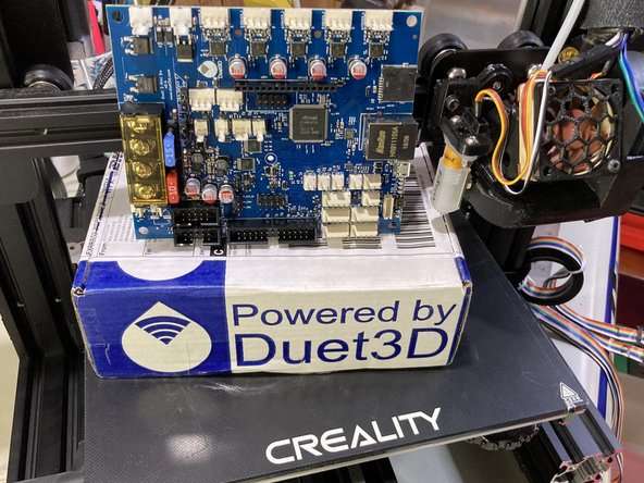
Now that we've copied the config files from the configurator, the web control interface files, menu system files, and firmware files, we are ready to power on the Duet Mini for the first time.
When you’re finished copying all the files and folders, safely eject the SD card from your computer system, and place the SD card into the Mini5+.
A micro USB cable capable of both data and power is now required to connect the board to your computer.
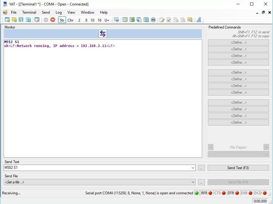
The next step is to connect to the board via USB and terminal software like YAT, Printrun/Pronterface, Cutecom, Serial Tools, etc.
See here for a detailed step by step tutorial on getting connected.
¶ Connect to the Duet Web Control
 You may already know the IP address of the Duet if you set a static IP address in the networking section of the previous guide.
If not, following the Connect Duet to Network section of the general getting connected guide to get the dynamic IP address assigned to your Duet 3 mini 5+ from the network.
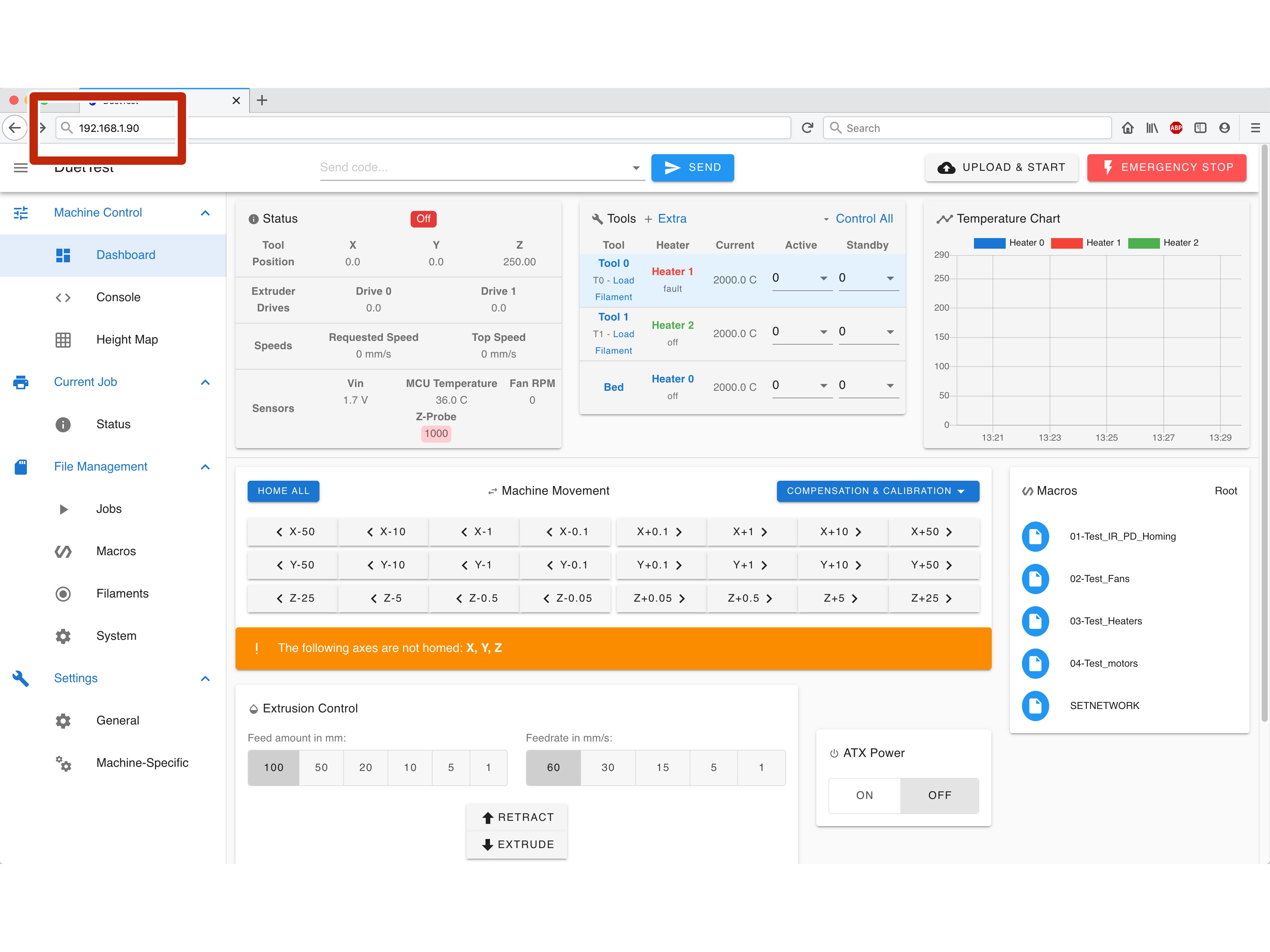
 Use the IP address and connect to Duet Web Control (DWC) using a browser.
You can familiarize yourself with the full Duet Web Control functionality in the DWC Manual.
¶ Verify Firmware is Updated
Go to the Settings > Machine Specific and General page on the left side bar. Compare the version numbers shown to the versions we copied to the SD card in the previous guide.
¶ Updating Firmware
If they are not the same the follow the updating firmware instructions.
¶ Testing End Stop Switches
Next, we will verify that the end stops are triggering properly.
Go to the Settings > Machine Specific > Endstops.
X, Y, and Z end stops should say "No"
Manually trigger the end stops with your finger, you should see the value change to "Yes" for each one you press.
If the values do not change, power down the printer and double check your wiring connections.
If the values for X, Y, and Z show "Yes" by default, and "No" when triggered, you chose the wrong switch type in the configurator. The easiest wya to change this is going to config.g, find the linse that start with M574 and either add or remove the ! mark before the pin name in the P parameter
¶ Verify Motor Direction
Before we try and home the printer we must verify the direction of the motors.
Go to the Gcode Console tab and send the command M18 to power off the motors.
Manually position the X and Y axis to their midway positions by hand. This means the bed and the print head are in the middle of their travel distances. The Z axis should be raised about a hand width above the bed.
Send G92 Z50 Y100 X100 which will force a verified axis position close enough for our test and allow us to command motor movement safely.
Go to the machine control tab and click on the X+1, Y+1, and Z+0.5 buttons one at a time. Verify that the motors move slightly in the expected direction. X+ should move the print head to the right. Y+ should move the bed towards the front. Z+ should raise the print head above the bed.
If the direction doesn’t match what you expect, you will need to go into Settings > System Editor and edit config.g, find the M569 command under the ;Drives section and change the S parameter of the drive in question. P0 = X, P1 = Y, P2 = Z
Changing a motor direction means you will also need to change the direction of the homing move for that axis by changing from a positive movement to a negative movement or vice versa. The homing files are found in the sys folder. Testing homing is covered next.
¶ Testing Homing Behaviour
Now that we have verified that the motors are moving in the right direction and the end stops are triggering correctly, we can try our first homing commands.
On the Machine Control tab, click the Home buttons for each axis, starting with X.
Warning! If the direction of movement is not towards the end stop, kill the power to the printer immediately.
When the printer starts to move, immediately press the endstop switch for the axis with your finger. Movement should stop, the direction should briefly reverse, and then try to home again. Trigger the endstop once more.
Warning! If the movement does not stop when you trigger the end stop, kill the power to the printer immediately.
When homing X the print head should move to the left towards the end stop switch.
When homing Y the bed should move to the back towards the end stop switch.
When homing Z the probe should deploy the pin and move towards the bed.
¶ Testing Homing Behaviour Part 2
When you are confident that each axis is homing in the correct direction and that the end stop switches halt the printer movement, you can continue.
First, home each axis one at a time and let it complete without triggering the endstop by hand.
The axis should move to the end of travel and trigger the end stop, reverse direction a few mm, and then go back to trigger the end stop again more slowly.
After confirming that each axis homes correctly on its own, you can test the Home All button.
Warning! If at any time behaviour is erratic, or behaves contrary to expectation, kill the power to the printer immediately.
If you had to reverse the direction of a motor in the previous step, you will need to change the direction of the homing moves in the homing files. See this wiki entry for further information on editing the homing files: Configuring RepRapFirmware for a Cartesian printer
See this wiki entry for further details: Test homing behaviour
¶ Testing the Hot End Heater
Ensure the nozzle and heater block is not in contact with anything and remove any loaded filament.
Command the hot end to 50c and watch the temp graph.
At 45c the hot end fan and case should start spinning.
Watch the temp graph to see if it stabilizes.
Command the hot end to 180c and watch the temp graph to see if It stabilizes.
Turn the hot end heater off (0c).
When the hot end temp drops below 45c the hot end fan should stop spinning.
If any of those steps don't proceed as expected, check for error messages in the console and investigate before proceeding. Double check wiring, check your heater and thermistor settings in config.g
¶ Testing the Bed Heater
Command the bed temp to 50c and watch the temp graph to see if it stabilizes.
Test the part cooling blower with the fan speed slider on the right side of the screen. Note if it has an effect on the hot end temperature.
As the hot end temp drops below 45c the hot end fan should turn off and the case fan should continue to spin.
Turn the bed heater off (0c).
When the bed temp drops below 45c the case fan should stop spinning.
If you encounter a heater fault, check this page: Spurious heater faults and how to avoid them
¶ Calibrate CPU Temp Reading
The CPU on the Duet has an internal temperature sensor, which can be very useful for gauging the temperature of the electronics case and the stepper drivers. However, before it can provide a useful result, it must be calibrated.
Following the procedure documented here: Calibrating the MCU temperature
Start with your printer at room temperature. As in, powered off for many hours.
Turn on the printer, and as quickly as possible read the MCU temperature from the Machine Status box at the top left of the screen. We will call this temperature Tc.
Now read the temperature of the hot end and bed. This should be very close to room temperature. Alternatively, if you have a thermometer in the room, you can use that value. We will call this Tr.
To calculate the offset value, use (Tr-Tc). This value may be positive or negative. We will use this resulting value in the following command.
In the Gcode Console, send M912 P0 S#, where # is the offset value obtained by (Tr-Tc). After a few seconds the CPU temperature should then read about the same as room temperature.
To make the calibration permanent, you must add that M912 P0 S# command to config.g. It doesn't matter where, but I put it near the end, before the M501 command and the T0 command.
¶ Tuning Fans
RepRapFirmware on the Duet allows you to fine tune the behavior of the PWM controlled fans. Every fan is a little different, and to get the best performance and acoustics out of it, you may want to experiment with different PWM frequencies, etc.
More information on how fans are controlled with the M106 command here: Gcode dictionary
On the Ender 3 used in this guide the best (quietest) results were found by using a frequency of 20Hz.
Values lower than 20 would tend to pulse, and values higher than 60 had a high pitched whine. Values above 1000 would not spin up.
With these changes, you may not even be tempted to replace the stock fans with quieter options, saving you time and money.
Bear in mind that cooling performance may be slightly impacted by reducing the PWM frequency. If you notice excessive stringing or jamming, try increasing the frequency and see if it is solved.
¶ Calibration
This concludes the commissioning stage of the guide.
For claibration please see the general RRF Calibration guide