¶ INDX Tool Board
Full support is still a work in progress. The configuration commands and macros described on this page are likely to change during the RepRapFirmware 3.7 beta cycle
This page is about using the Bondtech INDX tool board with Duet 3 or other electronics running RepRapFirmware.
The INDX documentation from Bondtech is here. It should be read in conjunction with this page.
¶ Features
- Controls induction heater, thermopile sensor, load cell and heatsink fan integrated with INDX toolhead
- Drives INDX tool head extruder motor, with closed loop option if a suitable diametrically-magnetised magnet is attached to the end of the motor shaft
- RGB LEDs on VF board displaying status information, visible via light pipes in the INDX toolhead
- Output for a print cooling fan with optional tacho
- Output for WS2812 or similar (Neopixel) LED string
- Supports connection of sensor coil for scanning inductive sensor
- On-board accelerometer
- Uncommitted input for endstop or similar
¶ Operating limits
| Stepper driver | Maximum 1.0A peak current, 0.71A RMS |
| FAN output on MCU board maximum current | TBD |
| Input power voltage | 24V +/- 2V |
| Power input max current | 4A |
| Inputs | IO_0 is 30V-tolerant |
| Fuses | None onboard. Use INDX Link board (4A fuse fitted), Duet 3 Tool Distribution Board (4A fuse fitted), or if directly connected to a power supply use an inline fuse holder with 4A or lower fuse depending on required current draw. |
| 5V (LED port) maximum load current | TBD |
| 3.3V (ENDSTOP/IO0_IN port) maximum load current | TBD |
| Maximum ambient temperature | 80°C |
¶ Hardware notes
The INDX tool board comprises two PCBs connected by two 20-way FFCs (Flexible Flat Cables). These will normally be supplied ready-mounted on a tool head.
The VF board is connected to the induction heater, IR temperature sensor, heatsink fan, and load cell. Do not make any other connections to the VF board, or remove the existing connections. The heatsink fan is connected to the VF board and defaults to running continuously; therefore it will run whenever no firmware is installed on the board, or firmware is being updated, or no configuration commands have been received from the main board.
The MCU board is connected to the rest of a Duet/RepRapFirmware system using a single XT30 2+2 connector. This provides power to the board (thick red and black wires, positive and ground respectively) and CAN FD (yellow and white wires, CANH and CANL respectively).
The board requires 24V nominal power, fused externally at 3A or 4A. We recommend that you use a Duet 3 Tool Distribution Board or INDX Link Board because they include the necessary fuse and simplify wiring. If the INDX is the only CAN-connected expansion in your system then you can instead use a direct CAN connection to the main board and an inline auto fuse in the positive supply wire.
The MCU board also provides the following connections:
- 4-pin connector for the stepper motor in the INDX toolhead
- 3-pin JST PA connector for the print cooling fan with optional tacho
- 3-pin IO0 connector, for an endstop or other input device
- 3 Pin connector for WS2812 (aka Neopixel) or similar LEDs
- 4-pin FFC connector for optional scanning inductive sensor coil. This requires a same side FFC (A-A) to connect to a standard Duet3D coil or the Bondtech SZP coil.
- 5-pin USB OUT connector. This is not used when running RepRapFirmware.
¶ Pin diagram

this is linked from the Bondtech documentation for convenience,
¶ Connecting the 20-way FFCs
If you need to disconnect and reconnect the FFCs linking the two boards, be aware of the following:
- Be sure to place the contact side of the FFC against the contacts in the socket
- Be sure to insert the cable straight into the middle of the connector. It is easy to insert a cable so that it is skewed and shorts the pins out. If you do this and then power up the board, it is likely to be damaged.
- The latching mechanisms on the vertical FFCs on the MCU board are counter-intuitive. They are unlatched when the latch is in the up position (away from the PCB). After inserting the FFCs, push the latch down towards the PCB to lock the FFC in place.
¶ Switch
RRF supports the CAN connection, so set the CAN <-> USB switch on the MCU board to the CAN position.
¶ Jumpers
The following jumper blocks are provided:
- 2-pin CAN_RESET jumper. Only install this if the firmware running on the board is non-functioning. When the board is powered up with this jumper installed, it tells the bootloader to reset the CAN address to default (121) and then fetch and install new firmware even if firmware is already installed.
- 2-pin CAN_TERM jumper. Install this if the board is the last board at one end of the CAN bus.
¶ Wiring
The Bondtech INDX tool head is normally supplied with an associated Link board. This board provides the following:
- 4A fuse in the VIN supply to the INDX tool head
- USB isolator to protect a host computer USB port from damage in the event of a USB malfunction (in particular, a broken ground connection). This is not required when using RRF because RRF does not use the USB port.
- Protection against VIN reverse polarity at the VIN terminal block.
¶ To use the Link board:
- Set the CAN<->USB switch on the Link board to CAN
- Connect the power and signal connectors of the cable supplied to the VOUT and DATA OUT pins of the Link board
- Connect the VIN power supply to the 2-way terminal block
- Connect the CAN IN connector to the CAN bus from your main board
- If the INDX tool is the last board on the CAN bus, do not connect anything to the CAN OUT port on the Link board, and install the termination jumper on the INDX MCU board
- If the INDX tool is not the last board on the CAN bus, connect the CAN OUT port to the next board in the chain, and do not fit the termination jumper on the INDX MCU board.
- Do not connect anything to the USB port on the Link board.
¶ To use a Duet Tool Distribution Board instead of the Link board
You will not have VIN reverse polarity protection.
- Choose an output on the Tool Distribution Board to connect the INDX tool to
- Replace the 5A fuse in that position of the Tool Distribution Board with the 4A fuse from the Link board
- Connect the power and data connectors of the supplied cable to the selected position on the Tool Distribution Board. If using a version 1.0 Tool Distribution Board then the connectors are compatible. If using a version 0.5 board then you will need to change the 2-pin PA connector on the cable to a 4-pin PH connector.
- See the Tool Distribution Board instructions for generic instructions for connecting tool boards
¶ LED indications
Aside from the status LEDs mounted on the VF board, LEDs are provided on the MCU board to indicate the following:
| Label | Colour | Function |
|---|---|---|
| VIN | Blue | Indicates presence of VIN power |
| 3.3V | Green | Indicates presence of 3.3V power from on-board regulator |
| ACT / LED 1 | Green | Indicates activity (other than regular time sync messages) on the CAN-FD bus |
| STATUS / LED 0 | Red | Status LED. See description below |
Status LED: In normal use, the red LED flashes slowly (approx 1Hz) in sync with the main board to indicate that it has CAN time sync, or flashes continuously and rapidly to indicate that it doesn't. It also flashes startup error codes, for example if the bootloader doesn't find valid firmware on the board. For a list of these error codes see CAN_connection basics.
¶ Software notes
The RepRapFirmware binary file for this board is called Duet3Firmware_TOOLINDX.bin.
The bootloader file for this board is called Duet3Bootloader-SAME5x_CAN_USB.bin.
Reported by M122 B121 as: SAME5x composite bootloader version 3.02 (the version number will increase with future versions, do not use a version prior to 3.02)
Available from Bondtech here: https://github.com/BondtechAB/indx-bootloader
The minimum RepRapFirmware version for this board is 3.7.0. This applies to the firmware running on the main board too. If older main board firmware is used then some of the functionality may be missing, in particular the heater and the load cell are unlikely to work.
The default CAN address (which is also the CAN address after the reset jumper is used) is 121.
The inductive heater is fast and powerful, therefore the standard RepRapFirmware default tool heater model is inappropriate. Heater tuning must be run before using the INDX tool. The heater must also be calibrated before it can be used, to account for small manufacturing differences between heaters. This calibration step is run when heater tuning is commanded. Tuning must be carried out with a tool present and locked in place.
CAUTION! The inductive heater is fast and powerful. It can easily heat the nozzle or other metalwork placed inside the heater coil to dangerously high temperatures. Use only the correct firmware versions, and keep the firmware up to date. If the nozzle assembly is not fully inserted into the heater coil or is misaligned, this can result in the temperature being under-read, resulting in heating to a higher temperature than was intended. Do not allow paper or other flammable material to enter the heater coil area.
¶ Pin names
For more information on pin names, see Pin Names.
RepRapFirmware 3 uses pin names for user-accessible pins, rather than pin numbers, to communicate with individual pins on the PCB. Pins can be defined for use by a number of GCode commands, e.g. M308, M574, M558, M950.
The RepRapFirmware 3 uses the pin name format expansion-board-address.pin-name to identify pins on expansion board, where expansion-board-address is the numeric CAN address of the board. A pin name that does not start with a sequence of decimal digits followed by a period, or that starts with 0. refers to a pin on the Duet 3 main board.
| Function | Pin location | RepRapFirmware pin name | Notes |
|---|---|---|---|
| Outputs | FAN (on VF board) | hsfan | Heatsink fan, VIN voltage |
| hsfan.tach | Pulled up to +5V | ||
| FAN (on MCU board) | pcfan | Intended for print cooling fan, VIN voltage | |
| pcfan.tach | Pulled up to +5V | ||
| LED | led | 5V drive for WS2812 or similar LED strings | |
| Inputs | IO_0 | io0.in | Input with 3.3V power provided, 30V tolerant |
| Coil FFC | coiltemp | Scanning Z probe coil temperature |
¶ Configuration
If you change the CAN address, the CAN address in the following commands will need to change from
121to match
Some of these functions require the INDX macro pack to be installed. See the INDX Macros section below.
¶ Induction heater and IR temperature sensor
The thermopile sensor is configured using the M308 command with sensor type "thermopile_tpis.object" and pin name "i2c". As well as the main output which provides nozzle temperature, it has two additional outputs which may be used for monitoring. Auxiliary output 1 has type "thermopile_tpis.ambient" and is the ambient temperature reported by the thermopile sensor. Auxiliary output 2 has type "thermopile_tpis.environment" and is the temperature of the nozzle surround reported by the auxiliary thermistor.
As at 2026-06-29 the M308 command to configure the thermopile sensor accepts the following parameters, however many of these are likely to be withdrawn in future. Only the S parameter should be needed in normal use.
- S Sensor number
- R Radiation exponent, must be between 3.8 and 4.4. The theoretical value is 4.0 but the sensor manufacturer recommends 4.2.
- F Object field of view times emissivity, expressed as a fraction of 256. Normally in the range 110 to 120.
- W Surroundings (as measured by the aux thermistor) field of view times emissivity, expressed as a fraction of 256. The sum of the F and W parameters should not exceed 256.
- T Aux thermistor resistance at 25C
- B Aux thermistor B parameter
- C Aux thermistor C parameter
The inductive heater is configured using the M950 command with the pin name "nozzleheat". The temperature sensor number in the M950 command must refer to the thermopile sensor primary output.
Example configuration, using sensor #1 for the nozzle temperature, heater #1, and the default CAN address (121):
M308 S1 Y"thermopile_tpis.object" P"121.i2c" A"INDX"                       ; configure thermopile main output
M308 S2 Y"thermopile_tpis.ambient" P"121.S1.1" A"Thermopile ambient"       ; configure thermopile ambient output (optional)
M308 S3 Y"thermopile_tpis.environment" P"121.S1.2" A"Hot end surround"     ; configure nozzle environment output (optional)
M950 H1 C"121.nozzleheat" T1                                               ; configure induction heater
During a tool change the INDX macros turn the heater off before the latch opens, and heat the new tool to its active temperature only after the head has left the dock. Standby temperatures are not used.
¶ Onboard temperature sensor
This helps monitor chamber and INDX MCU board temperature.
M308 S11 Y"board-temp" P"121.dummy" A"INDXboardtemp" ; Onboard INDX board sensor
The location of the thermistor is shown here:
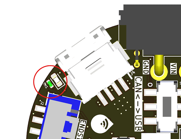
It is not immune from self heating on the INDX PCB, so it is not an absolute measure of the chamber temperature, but is a useful data point about the temperature of INDX mcu board which is useful, especially if running INDX in a heated chamber close to the design limits set by Bondtech.
¶ Heater tuning
Before first use the heater must be tuned using M303 with a tool loaded and locked in place.
The first heater tune will run a calibration so you cannot use the "A" parameter for the first heater tune.
Ideally the part cooling solution you plan to use will also be in place, however you can do an initial tune without it for testing. Before a print with part cooling it should be re-tuned with the part cooling solution in place.
Use the following command, assuming the INDX tool is tool 0 on your system:
M303 T0 S220
S220 = temperature to tune at. Select the temperature you will be printing at. If you plan to use a wider range of temperatures you can either tune at a middle temperature, or have multiple sets of M307 parameters and switch them in your start GCode or filament GCode.
¶ Heater feed forward
The INDX nozzles have a low thermal mass, so the flow of filament through the nozzle removes a significant % of the heat quickly. This action is compensated by an extrusion rate heater feed forward term set with M309.
Because the heater can respond so quickly to small changes in temperature the method of calibration shown there: Heater feedforward for the S parameter is not effective. We suggest starting with a S parameter of [TBC] and adjusting from there until heater faults are not generated at the maximum extrusion rate you plan to use for the nozzle size, type and filament.
¶ Extruder setup
Use the following commands, adjust if you have changed the CAN address
M584 E121.0  ; set extruder mapping
M350 E16 I1  ; configure microstepping with interpolation
M92 E561.4   ; equivalent to a rotation distance of 5.7mm at 16 microstepping
M566 E600    ; set maximum instantaneous speed changes (mm/min)
M203 E9000   ; set maximum speeds (mm/min)
M201 E3500   ; set accelerations (mm/s^2)
M906 E600    ; 600mA - If bondtech specify a different current use the one they recommend
¶ Fans
¶ Heatsink cooling Fan
The heatsink fan should be configured to run at full PWM when the nozzle is significantly above ambient temperature (e.g. above 45C). Here are suitable commands to configure it as fan #1, assuming again that the nozzle temperature sensor is sensor #1:
M950 F1 C"121.hsfan+hsfan.tach"     ; heatsink fan
M106 P1 C"Heatsink" H1 T45 S1       ; turn on when nozzle temperature is >= 45C
¶ Part cooling Fan
Directly connected fans
M950 F0 C"121.pcfan"
M106 P0 C"Part" S0                  ; turn off print cooling fan
if you use a directly connected part cooling solution with a tacho then:
M950 F0 C"121.pcfan+pcfan.tach"
¶ Tool
Assuming the heater and fan numbering used above, the tool configuration lines are as follows, adjust the number of lines based on the number of tools:
M563 P0 S"INDX" D0 H1 F0 ; create INDX tool 0
M563 P1 S"INDX" D0 H1 F0 ; create INDX tool 1
M563 P2 S"INDX" D0 H1 F0 ; create INDX tool 2
M563 P3 S"INDX" D0 H1 F0 ; create INDX tool 3
The dock positions are set in 0:/sys/INDX_variables.g, see Dock and speed settings.
The latch is driven by the extruder motor, and RRF discards extruder moves when no tool is selected. INDX_variables.g therefore also creates tool 9, "INDX latch", with no heater. The macros select it only to move the latch when no tool is selected. It shows in DWC but is not used for printing. Because of it, #tools is 10, so the macros use #global.INDX_tool_x for the number of INDX tools.
¶ Neopixel or other WS2812 LED strings
Use this command to configure an LED string connected to the LED port of the INDX board:
M950 E0 T1 C"121.led"
Then use M150 commands to set the LED colours.
¶ Accelerometer
¶ Configuration
Add the following to your config.g:
M955 P0 C"121.i2c.lis" I16 ; Configure INDX accelerometer
See M955 for how to set up and configure the accelerometer.
¶ Orientation
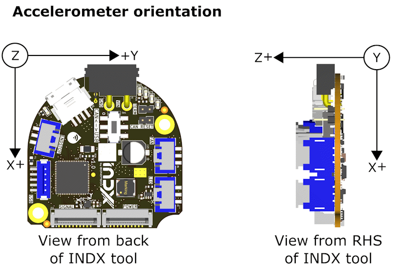
In the normal INDX mounting orientation, with tools picked up from the front Z+ of the accelerometer is +Y on the machine, and +X is oriented to -Z. So the correct command is
M955 P0 C"121.i2c.lis" I16
If you have tools mounted on the rear instead and the INDX head mounted backwards, then Z+ of the accelerometer is -Y, and +X is oriented to -Z. so the correct command is
M955 P0 C"121.i2c.lis" I56
¶ Calibration and usage
For an overview of using accelerometers to capture data on axis movement see: Connecting an accelerometer
¶ Loadcell
The load cell in the INDX toolhead is used as a Z probe: the nozzle probes the bed directly and the probe triggers when the contact force reaches the configured threshold.
To use the macros provided for INDX without modification it is recommended you configure the Loadcell as probe 0 as shown in the example below.
Add the following to your config.g:
M558 K0 P12 C"121.loadcell" V0.11
G31 K0 P50 Z0
Probe type 12 is a load cell probe. The trigger comparison runs on the tool board at the full ADC sample rate (about 1.3kHz), so the trigger latency is around a millisecond and probing speeds of 300mm/min are practical.
M558 V is the load cell scale in grams per raw ADC count and is required for this probe type. The INDX calibration macros described below determine it from the known tool locking force (about 1600g). The actual calibration value can change somewhat (~10%) between tools. The sign of V must be chosen so that the force reported in the object model (sensors.probes[0].loadCell.force, shown in DWC) goes positive when the nozzle is pushed towards the bed. Test this by pressing the nozzle upwards by hand with a tool locked; if the force reading goes negative, negate V. Pin inversion (!) is not supported on the load cell input.
G31 P is the trigger force in grams. The firmware tares the load cell automatically when a probing move starts, so the threshold is relative to the resting force at that moment and no manual tare is needed before probing. Between probing moves the baseline tracks slow drift by itself, so the displayed force stays near zero while the machine is idle; a step change such as locking or unlocking a tool is absorbed within a few seconds, or immediately by sending M558.4 K0. 40 to 70g is a reasonable starting point.
Note: INDX_variables.g applies G31 K0 P{global.INDX_LC_trigger_grams}, so with the macros installed the P value in config.g is overwritten.
Optionally M558 U<low>:<high> sets a safe window in grams for the preload, i.e. the resting force latched by the tare (sensors.probes[0].loadCell.preload). A probing move is refused if the preload is outside the window when the move starts. This catches probing without a locked tool or with a badly seated tool.
Test in the air before the first real probe: start a probing move well above the bed and press the nozzle upwards by hand. The move must stop immediately. This verifies the threshold and the sign of V without risking a head crash.
¶ SZP
The scanning z probe coil, if attached, is set up as a second Z probe. It integrates the same inductive sensing chip as the Duet 3 Scanning Z Probe. It allows for a point mesh of the bed to be built up quickly as no movement in Z is required to read the bed distance, and individual readings happen very quickly.
¶ Mounting
The INDX tool has an optional mount for the SZP coil that should be used. It ensures correct mounting distance from the bed. It places an official Bondtech SZP coil 3mm above the nozzle, centered on X and 35.1mm on +Y relative to the nozzle, assuming the tool is mounted to pick up tools at Ymin (as is conventional). (Measured in CAD)
If an alternative mounting solution is used then aim for a 3mm Z offset between the tip of the nozzle and the underside of the coil.
¶ Configuration
To use the macros provided for INDX without modification it is recommended you configure the SZP as probe 1 as shown in the example below.
Add the following to your config.g:
; Scanning Z probe
M558 K1 P11 C"121.i2c.ldc1612" F12000 T12000
M308 S10 Y"thermistor" P"121.coiltemp" A"SZP coil temp" ; thermistor on SZP coil
M558.2 K1 S15 R134990
G31 K1 X0 Y35.1 Z3.5 ; set SZP probe trigger value, offset and trigger height
; Mesh Bed Compensation
M557 X-100:100 Y-64.9:100 S10 ; define grid for mesh bed compensation probe 1
The M558.2 parameters need to be calibrated, see the next section.
The M557 mesh parameters need to be set to your bed co-ordinates that the coil can reach. The example is for a 200x200 bed with the zero point in the center. The front edge is Y-64.9 because the probe cannot go further forward than
global.safeYmin(-100) plus the SZP Y offset (35.1).
¶ Calibration and usage
For general information about SZP calibration and usage, see Scanning Z Probe calibration
¶ Endstop
The endstop input on the MCU board can be used for any digital IO function. The most common use is to home the tool along the X axis. The configuration line for this is:
M574 X1 P"121.io0.in" S1 ; configure X axis endstop on the low end of the X axis
¶ Motor encoder
To follow. This requires a diametrically polarised magnet attached to the back of the motor shaft and the INDX MCU mounted ~1mm from the magnet. At the time of writing (11 August 2026) this magnet was not being provided in INDX units.
For testing the following command will report the angle and encoder status in M122 after the encoder is configured
M569.1 P121.0 T3
¶ Bed Mesh
The INDX tool head allows us to mesh with either the loadcell or the SZP probe. The loadcell will take longer to mesh the entire bed, however it is measuring the actual surface, and not the metal that is potentially below the surface (for example, on coated beds). Also, if there are gantry twists or other mechanical issues with the machine, the load cell will produce a more accurate mesh because the SZP coil is displaced from the nozzle tip and so will move differently relative to the nozzle tip with those mechanical issues. On the other hand the SZP mesh is much quicker to perform at a high probe density.
The recommendation is to mesh with first the load cell and then the SZP and compare those meshes. Then a decision can be made to use the SZP mesh if it is close enough, correct mechanical twists if possible, or stick with the loadcell mesh.
¶ Using G29 with the INDX example mesh.g
G29 -> SZP scanning probe (default)
G29 K1 -> SZP scanning probe
G29 K0 -> INDX load cell, i.e. the nozzle touches the bed at each point
The default area and spacing are set in INDX_variables.g (global.INDX_mesh_min, global.INDX_mesh_max and global.INDX_mesh_spacing, default 30 mm) and are shared by both probes. mesh.g applies them with M557, so the M557 in config.g is only the power-up default.
The grid can be overridden per run, so a print start script can mesh just the area it needs:, e.g G29 K0 X{-50,50} Y{-40,40} I20
X{min,max} Y{min,max} area in probe coordinates (default global.INDX_mesh_min/max)
I<spacing> [J<Y spacing>] point spacing in mm (default global.INDX_mesh_spacing)
F"name.csv" extra copy of the height map
Use I, not S, for the spacing: G29 reads S as its own subfunction. The area is trimmed to what the probe can reach with the head at or above global.safeYmin, with a warning.
The firmware moves the head so the PROBE is over each grid point, using the G31 X/Y offsets, so the area is in probe coordinates.
Height maps written, so the last run of each probe is always available for comparison:
heightmap.csv the run that just finished - this is the active map
heightmap_loadcell.csv the last load cell run
heightmap_SZP.csv the last SZP run
For both probes the X and Y must be homed and a tool must be loaded: the SZP establishes the Z datum with the load cell, which needs the nozzle.
¶ INDX Macros
These macros are a work in progress. This section describes the macros as a whole, see individual function parts of the documentation for how to use them.
The macros are hosted on Bondtech's Github here:
Bondtech INDX RRF Macros
¶ Global variables
Global variables are used to synchronise information between the various macros for INDX calibration and tasks such as load cell probing. To make them easier to manage, these variables are contained in 0:/sys/INDX_variables.g which is put in the sys directory as part of the macros bundle.
Add M98 P"INDX_variables.g" to the end of config.g to run this file on startup.
After editing the file, send M98 P"INDX_variables.g" to apply the changes without a restart. global.INDX_State keeps its current value, because the saved state is only read at startup.
¶ Dock and speed settings
These variables in 0:/sys/INDX_variables.g set the dock positions and the tool change speeds. All positions are machine coordinates. The defaults/example values are for the Duet3D test machine; measure the positions on your own machine.
| Variable | Default | Description |
|---|---|---|
global.INDX_tool_x |
{-110, -65.5, -19, 27} |
X centre of each dock in mm. The index is the tool number. Add one entry for each INDX tool defined with M563. |
global.INDX_dock_y |
-127 |
Y in mm at which a tool is fully seated in its dock. Shared by all docks. |
global.INDX_dock_dir |
-1 |
Y direction into the docks: -1 if the docks are at the Y minimum, +1 if at the Y maximum. |
global.INDX_trigger_offset |
5.0 |
Distance in mm from the dock line back to the trigger line, where the head stops before the latch moves. |
global.INDX_peel_distance |
10.0 |
Distance in mm the head moves back from the dock line at contact speed after a drop-off or pickup, to clear the dock pins. |
global.INDX_z_hop |
1.0 |
Z raise in mm before travelling to a dock. 0 disables it. |
global.INDX_TC_SPEED |
24000 |
Travel speed in mm/min. |
global.INDX_TC_MODE |
1.0 |
Multiplier on global.INDX_TC_SPEED, e.g. 0.3 for the first tests. |
global.INDX_TC_contact_speed |
1000 |
Maximum speed in mm/min for moves within the slow zone. |
global.INDX_TC_slow_zone |
10 |
Distance in mm from the dock line within which moves run at the contact speed. It is never less than global.INDX_trigger_offset. |
¶ Safe Y minimum
The default/example value is for the Duet3D test machine; measure the positions on your own machine.
global.safeYmin (default -100) is the lowest Y the head can reach outside a tool change. It keeps the head clear of the tools in the docks.
- At startup
INDX_variables.gstores the config.gM208Y minimum inglobal.INDX_Y_hard_min, then raises the Y minimum toglobal.safeYmin. - Normal moves cannot go below
global.safeYmin. - Only the tool change macros go below it. They turn the axis limits off with
M564 S0in the dock area and turn them back on when the head returns toglobal.safeYmin. - The example
homez.g,mesh.g,pause.gandstop.gmove the head toglobal.safeYmin, not below it.bed.gaborts if a levelling point is outside the axis limits, andmesh.gtrims the mesh area to what the probe can reach. - The config.g
M208Y minimum must be at or belowglobal.INDX_dock_y. The tool change macros abort if the dock is outside it. - Set
global.safeYminso that the head, with a tool locked on, clears the tools in the docks.
¶ Debugging
global.INDX_DEBUG turns debugging output on (1) or off (0). When it is on, the INDX macros print additional information for many operations. Send set global.INDX_DEBUG = 1 to turn it on. The value is saved by INDX_WRITE_STATE.g and restored at startup.
¶ INDX Write State
Some global variable values that are set during calibration routines or tool changes need to persist between machine reboots. The 0:/sys/INDX_WRITE_STATE.g macro writes these variables to 0:/sys/indx-state.g which is run at the end of 0:/sys/INDX_variables.g to restore saved variables.
Currently the active tool is written twice every tool change (once when the latch opens and once when it locks). This will be made optional in the future to reduce SD card wear.
This state is used in config.g to select the tool that was on the head at the last recorded tool change. Put the following in config.g at the end, after the INDX_variables.g line
; Re-select whatever tool indx-state.g says is physically on the head
if global.INDX_State >= 0 && global.INDX_State < #global.INDX_tool_x
  T{global.INDX_State} P0
elif global.INDX_State = 99
  echo "config.g: latch is closed but the tool is unknown - no tool selected. Run INDX_OPEN or set global.INDX_State."
¶ global.INDX_State values
| Value | Meaning |
|---|---|
| -1 | Latch open, no tool on the head |
| 0 to n | That tool is locked on the head |
| 99 | Latch closed, tool unknown |
The tool change macros set global.INDX_State and save it with INDX_WRITE_STATE.g. INDX_OPEN.g sets -1 and INDX_CLOSE.g sets 99, and both save it. INDX_LC_CALIBRATE.g asks which tool was seated, then sets the state to that tool and selects it. The state is saved if the calibration is saved.
¶ Recovering from a state mismatch
The tool change macros stop if global.INDX_State does not match the selected tool, for example INDX_TC_FREE: T0 is selected but global.INDX_State is 1. To recover:
- Check which tool, if any, is on the head.
- If tool n is on the head, send
set global.INDX_State = nthenT<n> P0. - If the head is empty and the latch is closed, run
M98 P"INDX_OPEN.g". If the head is empty and the latch is open, sendset global.INDX_State = -1thenT-1 P0. - Unless
INDX_OPEN.gwas used, sendM98 P"INDX_WRITE_STATE.g"so that the corrected state is used after a restart.
P0 selects or deselects the tool without running the tool change macros. Do not use T<n> without P0 to correct the state, because that starts a tool change.
¶ Tool management macros
0:/sys/INDX_OPEN.g - Open the tool
0:/sys/INDX_CLOSE.g - Normal close of the tool
0:/sys/INDX_LATCH_ENGAGE.g - A further 3 mm slow latch move, to make sure a closed latch is fully engaged
0:/sys/INDX_LATCH_MOVE.g - Moves the latch motor for all the latch macros, selecting the latch tool if no tool is selected
0:/sys/INDX_UNLOCK_DANCE.g - Releases a tool seated in its dock, called by INDX_TC_FREE.g
0:/sys/INDX_TC_REPORT.g - Logs each tool change check and acts on a failure, called by the tool change macros
0:/sys/INDX_TOOL_CHECK.g - Confirms a tool is on the head with a short heat check, called by homez.g, bed.g and mesh.g
¶ Tool change macros
There is one tool change macro for each of the steps:
INDX_TC_FREE.g park the tool on the head in its dock, called from tfreeN.g
INDX_TC_PRE.g move the head to the trigger line of the dock of the tool about to be picked up, called from tpreN.g
INDX_TC_POST.g lock the new tool on and leave the dock, called from tpostN.g
So there still need to be as many tfreeN.g,tpreN.g and tpostN.g macros as there are tools defined, but they all just call the same INDX_ macros. For example:
; tfree0 - free tool 0
M98 P"INDX_TC_FREE.g" T0
; tpre0 - approach the tool 0 dock
M98 P"INDX_TC_PRE.g" T0
; tpost0 - engage and lock tool 0
M98 P"INDX_TC_POST.g" T0
Note: Using the example macros, the standby temperatures set by the slicer or otherwise are overwritten with 0 at the next tool change: on pickup by INDX_TC_PRE, and on park by INDX_TC_FREE.
¶ Tool change sequence
RRF runs tfree for the old tool, then tpre and tpost for the new tool. All XY moves use G53 machine coordinates and set both X and Y, so tool offsets and the previous head position do not affect them.
INDX_TC_FREE.g (drop-off):
- Turn the heater off.
- Raise Z by
global.INDX_z_hop. - If the head is below
global.safeYmin, move out in Y only. - Travel along
global.safeYminto the dock X. - Move to the slow zone at travel speed, then to the trigger line at contact speed.
- Release the tool: small latch moves alternate with Y moves to the dock line, then the latch opens fully.
- Move back by
global.INDX_peel_distanceat contact speed, then toglobal.safeYmin. - Run the drop-off checks.
INDX_TC_PRE.g (approach to the next tool):
- Raise Z by
global.INDX_z_hop, unless the drop-off has already raised it. - If the head is below
global.safeYmin, move out in Y only. - Travel along
global.safeYminto the dock X. - Move to the slow zone at travel speed, then to the trigger line at contact speed.
INDX_TC_POST.g (pickup):
The latch is locked here, not in INDX_TC_PRE.g, because no tool is selected while tpre runs.
- Move to the dock line at contact speed.
- Lock the latch.
- Move back by
global.INDX_peel_distanceat contact speed, then toglobal.safeYmin. - Run the load cell check.
- Lower Z to the height before the tool change.
- Run the heat check, then heat to the tool's active temperature.
After T-1, only the drop-off runs, so Z stays raised by global.INDX_z_hop. A later pickup from no tool returns Z to the height it started at.
¶ Tool Change Checks
The tool change macros conduct a number of checks to make it more likely that a failed pickup or drop-off will be detected.
INDX_TC_FREE.g (drop-off):
- X and Y must be homed before any movement.
- A tool must be on the head to drop off (as recorded in
global.INDX_State). - The dock position must be within the machine axis limits.
- A head below
global.safeYminfirst moves out in Y only, clear of the docks. - Load cell: the reading must be at least 700 g above this dock's empty-head reading.
- Load cell: the clamping force must drop by at least 700 g as the latch opens.
- Temperature (tools above 70 °C): the IR reading must drop faster than normal cooling.
INDX_TC_PRE.g (approach to the next tool):
- The head must be empty before approaching a dock (as recorded in
global.INDX_State). - The dock position must be within the machine axis limits.
- A head below
global.safeYminfirst moves out in Y only, clear of the docks. - Load cell: the reading must be within 700 g of this dock's empty-head reading.
INDX_TC_POST.g (pickup):
- The head must be at the dock trigger line left by
INDX_TC_PRE.g; otherwise nothing moves. - Load cell: the clamping force must rise by at least 700 g as the latch closes.
- Heat: heating must raise the nozzle temperature by 3 °C within 5 seconds.
When a check fails, global.INDX_TC_check_action sets what happens: 0 shows a warning, 1 stops the tool change. The thresholds are set in INDX_variables.g. The load cell checks are skipped if the load cell is not calibrated. If no tool was picked up, the heat check also produces a heater fault ("inductive heater load error: is a tool loaded?").
The empty-head checks always stop the tool change, whatever global.INDX_TC_check_action is set to. Each dock's empty-head reading is taken during a successful tool change and is lost at restart, so these checks start after the first change at each dock.
¶ Loadcell Macros
¶ Calibration
In order to calibrate and then probe with the load cell the following macros are used:
0:/sys/INDX_LC_CALIBRATE.g - A guided calibration routine that prompts the user to take steps to achieve load cell calibration and saves the calibration
0:/sys/INDX_TARE.g - Capture the empty-head baseline for load-cell CALIBRATION
0:/sys/INDX_CLOSE_CAL.g - Locks the latch, then seats it a further 1 mm at low speed to achieve the ~1600g force specified by Bondtech
0:/sys/INDX_LC_CAL.g - Computes grams/count against the known force.
A one-line macro in 0:/macros containing M98 P"0:/sys/INDX_LC_CALIBRATE.g" makes the calibration available in the DWC Macros list.
¶ Z Probing
0:/sys/homez.g - an example homez.g - adapt for your specific machine
0:/sys/bed.g - for 3 point bed levelling (e.g. on a voron trident).
0:/sys/mesh.g - for bed mesh using the loadcell or SZP - see the Bed Mesh section above.
0:/sys/INDX_LC_RAW.g - read the raw load cell level into global.INDX_LC_raw (used by tool change macros)
0:/sys/INDX_LC_RETARE.g - zero the reported load cell force
¶ Homing
- Homing files must not select or change the tool. The tool is selected at startup from
global.INDX_State, and after that only by tool changes. - Home X and Y before Z. The tool change macros and
homez.gstop if X and Y are not homed. homez.g,bed.gandmesh.gneed a tool locked on the head and selected, and a calibrated load cell, because the nozzle is the probe.INDX_TOOL_CHECK.gconfirms the tool is there with a short heat check: the nozzle must rise 3 °C within 5 seconds.homez.gends with the head atglobal.safeYmin.- With
global.INDX_DEBUGset to 1,homez.gprobes a second time and reports the difference from the trigger height.
¶ Testing
0:/macros/INDX_TC_TEST.g - Optional soak test. It cycles through every tool a set number of times and logs every tool change check. See the comments at the top of the file for its parameters.
¶ Resuming a print
resurrect-prologue.ghas not been extensively tested. Test it on your machine before relying on it.
0:/sys/resurrect-prologue.g prepares the machine when a print is resumed with M916. resurrect.g calls it with the X, Y and Z at which the print stopped.
- If
global.INDX_Stateshows no tool on the head, it turns the tool heaters off. It stops if the state is 99. - It shows the saved state and the stop position, and waits for confirmation that the head matches and is clear of the docks.
- It homes X and Y.
- It selects the tool recorded in
global.INDX_StatewithP0, so no tool change runs. - If Z is not homed, it takes Z to be 5 mm above the stop height, where
pause.gleft it. This lift must match the Z lift inpause.g.
resurrect.g then selects the print tool with a normal T command, which runs a tool change if a different tool is on the head.