¶ Overview
A Z probe can be used to accurately, automatically and repeatably set the Z height, assist in the manual adjustment of the bed level, and/or allow automatic correction/compensation for errors of bed squareness and flatness. On a delta machine, it can automatically calibrate the machine dimensions.
Differing Z probe technologies vary in their ability to deliver reliability, simplicity, accuracy and low cost and no single type predominates. For a comparison of advantages and disadvantages for various Z probe options see Choosing a Z probe.
Once you have the probe connected, see how to:
- Test and calibrate a Z probe
- Setting up automatic probing of the print bed
- Using the Manual Bed Levelling Assistant
- Bed levelling using multiple independent Z motors
- Mesh bed compensation
If you don't have a Z probe, you can still use mesh bed compensation and other features normally associated with a Z probe. See Mode 0 below.
¶ Duet Z probe pins
You can connect a Z probe directly to your Duet.
- On Duet 3 boards, you can connect a probe to any IO connector. Some probes may need specific capabilities e.g. analog input or PWM output; see the hardware overview for your board for IO connector capabilities.
- The Duet 2 WiFi / Ethernet provides a dedicated 4-pin connector.
- The Duet 2 Maestro provides a dedicated 5-pin connector.
Caution! The following table shows the pinout out by function, and NOT the physical order. Check the wiring diagram of your Duet for the correct pinout order. For example, the pinout of the 5-pin IO_ connectors on Duet 3 is NOT the same as the pinout of the 5-pin Z Probe connector on Duet 2 Maestro!
| Duet 3 IO_x pin label | Duet 2 WiFi/Ethernet pin label | Duet 2 Maestro pin label | Purpose |
|---|---|---|---|
| IN | IN | IN | Input from Z probe |
| GND | GND | GND | Ground |
| OUT | MOD | MOD | Control signal for some types of Z probe |
| 3.3V | 3.3V | 3.3V | Power to Z probe |
| 5V | - | 5V | 5V power to Z probes that need it (e.g. BLTouch) |
Note: The MOD pin on the Duet 2 WiFi/Ethernet is NOT PWM capable, so can't be used to control a servo. The OUT pin on Duet 3 and the MOD pin on the Duet 2 Maestro are PWM capable, and can control a servo (eg to deploy BLTouch).
¶ Z probe modes selectable in firmware
The M558 Gcode configures the firmware for your Z probe. Using the P parameter configures the firmware to recognise the output mode of the Z probe you are using. For example, M558 P1 selects Z probe mode 1.
- You can use a Z probe with either an analog or a digital output; just set the mode in M558 accordingly.
- Some types of Z probe with digital output should be connected to the E0 endstop connector instead of the Z probe connector.
- In firmware versions before 3.2, when using a probe with analog output, the firmware will slow down the probe speed when it is getting close to trigger height.
- If updating from RRF 2.x, and the probe used type 4, 6 or 7, use type 5 or 8 instead, and define the pin the probe is connected to with the C parameter in M558.
- Probes connected to Duet 3 expansion boards must be probe type 8 or 9 (stall homing not currently supported on expansion boards). Firmware 3.5 also supports type 11.
- In firmware versions from 3.2, you can use the F parameter in M558 to specify a fast Z feedrate for the first probing move, followed by a slower second probing move, for any probe. eg M558 F600:120
The following table gives an overview of the different Z probe modes.
| Mode | Probe type | Control signal (MOD or OUT pin) |
|---|---|---|
| 0 | No probe | Not used |
| 1 | Analogue probe | HIGH |
| 2 | Analogue probe with modulation | Modulation (IR LED on/off control) |
| 3 | Analogue probe | LOW |
| 5 | Digital probe | HIGH during probing, LOW at other times |
| 8 | Digital probe, unfiltered | HIGH during probing, LOW at other times |
| 9 | BLTouch | OUT (Duet 3) and MOD (Duet 2) can be configured to control deployment/retraction. MOD on Duet 2 WiFi/Ethernet is not PWM capable, so use heater pin on expansion port instead. |
| 10 | Z motor stall detection | Not used |
| 11 | Scanning Z probe with an analog output (from RRF 3.5.0) | N/A |
¶ Z Probe Mode details
¶ Mode 0
Select this mode if you have no Z probe. When the firmware tries to execute a command to probe the bed, it will instead show a dialogue in Duet Web Control, and also on Panel Due, asking you to jog the head down until the nozzle just touches the bed and then press the OK button.
¶ Mode 1
This is a probe with an analog output connected to the Z probe connector. The probe output must rise as it gets closer to the bed. If the probe output falls as it gets closer, invert the probe output by prefixing the input pin name (C parameter) with ! character, in the M558 command. The control signal is driven HIGH.
¶ Mode 2
This is a probe with an analog output that requires the Duet to provide modulation signal and demodulate the returned signal. The probe output rises as it gets closer to the bed. If the probe output falls as it gets closer, invert the probe output by prefixing the input pin name (C parameter) with ! character RRF 3.x in the M558 command. The Duet drives the control signal with a 250Hz square wave. The firmware extracts that part of the analog signal received on the IN pin that is in phase with the modulation.
¶ Mode 3
As mode 1 except that the control signal is driven LOW.
¶ Mode 5
A switch or digital output device connected between the STP or IN and GND terminals of the connector. The only pullup resistor is the 100K nominal pullup in the microcontroller so the sink current requirement is tiny. The input must be active high when triggered.
Select the input pin with the C parameter in the M558 command. Invert the probe output to select active low by prefixing the input pin name (C parameter) with ! character in the M558 command
¶ Mode 8
Similar to mode 5 except that the input is not filtered, for slightly faster response. Supported in firmware 1.20 and later.
¶ Mode 9
Special mode for BLTouch and similar probes, that need to be deployed and then retracted for each probe point. Supported in firmware 1.21 and later.
¶ Mode 10
Use the Z motor stall detection as the Z probe trigger. Supported in firmware 1.21 and later. There are limitations to stall detection and it is not always appropriate for accurate Z probing, however there is a detailed discussion on the forum and some users have had success.
¶ Mode 11
Scanning Z probe with an analog output (supported from RRF 3.5.0-beta.4). Such probes must be calibrated before use (see M558.1). See Duet 3 Scanning Z Probe, Duet 3 Roto toolboard and Scanning Z probe calibration
¶ Configuring multiple probes
From RRF 3.1.0, you can define multiple probes.
- The K parameter in M558 selects the Z probe number. If there is no K parameter then 0 is used. You can ignore this parameter if you have only one Z probe.
- Z probe #0 can use probe types 0, 1, 2, 3, 5, 8, 9, 10 or 11 (RRF 3.5 and later). All other probes must be probe type 0, 8, 9, 10 or 11 (RRF 3.5 and later).
The following table gives an overview of the different Z probe modes.
| Mode | Probe type | Control signal (MOD or OUT pin) |
|---|---|---|
| 0 | No probe | Not used |
| 1 | Analogue probe | HIGH |
| 2 | Analogue probe with modulation | Modulation (IR LED on/off control) |
| 3 | Analogue probe | LOW |
| 4 | Digital probe connected to E0 endstop input, or endstop input set by C parameter | Not used |
| 5 | Digital probe connected to Z Probe input | HIGH during probing, LOW at other times |
| 6 | Digital probe connected to E1 endstop input | Not used |
| 7 | Switch triggering Z endstop | Not used |
| 8 | Digital probe connected to Z Probe input, unfiltered | HIGH during probing, LOW at other times |
| 9 | BLTouch with output connected to Z Probe input | OUT (Duet 3) and MOD (Duet 2 Maestro) can be configured to control deployment/retraction. MOD on Duet 2 WiFi/Ethernet is not PWM capable, so use heater pin on expansion port instead. |
| 10 | Z motor stall detection | Not used |
¶ Z Probe Mode details
¶ Mode 0
Select this mode if you have no Z probe. When the firmware tries to execute a command to probe the bed, it will instead show a dialogue in Duet Web Control, and also on Panel Due if you are running recent Panel Due firmware, asking you to jog the head down until the nozzle just touches the bed and then press the OK button.
¶ Mode 1
This is a probe with an analog output connected to the Z probe connector. The probe output must rise as it gets closer to the bed. If the probe output falls as it gets closer, invert the probe output by adding the I1 parameter in the M558 command. The control signal is driven HIGH.
¶ Mode 2
This is a probe with an analog output that requires the Duet to provide modulation signal and demodulate the returned signal. The probe output rises as it gets closer to the bed. If the probe output falls as it gets closer, invert the probe output by adding the I1 parameter, in the M558 command. The Duet drives the control signal with a 250Hz square wave. The firmware extracts that part of the analog signal received on the IN pin that is in phase with the modulation.
¶ Mode 3
As mode 1 except that the control signal is driven LOW.
¶ Mode 4
The trigger signal is read from the E0 endstop circuit. You can choose whether the signal is high or low when triggered. In firmware 1.15 and earlier this is done by using M574 E0 S1 to select active high, or M574 E0 S0 to select active low. In firmware 1.16 to 2.x, use I1 in the M558 command to select active low, otherwise it defaults to active high.
The device connected to the E0 STP pin must be able to sink 1.5mA for the Duet 2 WiFi and Duet 2 Ethernet, 0.3mA for the Duet 2 Maestro, or 2.1mA for the Duet 0.6 or 0.8.5. In firmware 2.03 and later you can choose a different endstop input using the C parameter of the M558 command.
¶ Mode 5
A switch or digital output device connected between the STP or IN and GND terminals of the connector. The only pullup resistor is the 100K nominal pullup in the microcontroller so the sink current requirement is tiny. The input must be active high when triggered.
Similar to mode 4 except that the Z probe connector is used. In firmware 1.16 and later you can use the I1 parameter in the M558 command to invert the probe signal to select active low.
¶ Mode 6
Similar to mode 4 except that the E1 endstop input is used. Deprecated in firmware 2.03 and later, use mode 4 with parameter C4 instead.
¶ Mode 7
Similar to mode 4 except that the Z endstop input is used. Deprecated in firmware 2.03 and later, use mode 4 with parameter C2 instead.
¶ Mode 8
Similar to mode 5 except that the input is not filtered, for slightly faster response. Supported in firmware 1.20 and later.
¶ Mode 9
Special mode for BLTouch probe. Supported in firmware 1.21 and later.
¶ Mode 10
Use the Z motor stall detection as the Z probe trigger. Supported in firmware 1.21 and later. There are limitations to stall detection and it is not always appropriate for accurate Z probing, however there is a detailed discussion on the forum and some users have had success.
¶ Controlling deployable probes
Some probes, for example BLTouch, Creality CR Touch, BIQU Microprobe, Klicky and Euclid, need to run commands before and after probing, to enable them, e.g. a set of movement commands to pick them up, or control a servo to activate them. RRF has a mechanism to allow for this; when a probing command (G29, G30, or G38.x) is called, RRF checks if there is a system macro called deployprobe.g in the /sys folder. If there is, it will run this before probing. At the end of the probing, RRF will run retractprobe.g.
From RRF 3.1, if you have more than one Z probe, you can use deployprobe0.g and retractprobe0.g for probe 0, deployprobe1.g and retractprobe1.g for probe 1 and so on. RRF first looks for deployprobeN.g (where N is the probe number). If that's not found and the probe number is 0 then it falls back to deployprobe.g. In RRF 3.5, it always falls back to deployprobe.g and it passes the probe number in the K parameter. Similar for the retractprobe.g macro.
NOTE: If you DO NOT have a Z probe that needs to deploy or retract, you must not have these files in the /sys/ directory, or the firmware will attempt to use them!
Additionally, if you have two probes, and one deploys (eg probe 0) and the other (eg probe 1) does not, ONLY have deployprobe0.g and retractprobe0.g in /sys, i.e. no deployprobe.g/retractprobe.g or deployprobe1.g/retractprobe1.g. Alternatively, in RRF 3.5 or later, use deployprobe.g/retractprobe.g only, but use Meta Gcode and the passed probe number (K parameter) to control what happens when each probe is used.
¶ Notes on probe deployment
- Users can deploy and retract probes manually using M401 and M402
- G30 requests deployment of the probe before probing (unless the user has previously called M401 without subsequently calling M402) and retraction of the probe afterwards
- In G29, if the probe is not a mode 9 probe (e.g. BLTouch) then it requests deployment at the start of the entire sequence and retraction at the end. If it is a mode 9 probe (e.g. BLTouch) then it requests deployment and retraction for each individual point.
- Each probe keeps track of the deployment state. When the count goes from 0 to 1, the deployment macro is called. When it goes from 1 to 0 the retraction macro is called. Otherwise nothing is done apart from adjusting the count.
- M401 will always call a deployment, M402 will always call a retraction, irrespective of the count, but the count is updated with the current state (deployed or retracted).
- For G32 when not using a BLTouch it's typical to use M401 at the start and M402 at the end of bed.g, to avoid deploying and retracting the probe at each point. (edited)
- All probe types run deployprobe.g and retractprobe.g. For most types it is run just once per set of points, but for type 9 it runs them on every probing operation.
¶ Connecting different types of Z probe
¶ Mini differential IR sensor by dc42
With Duet 2 and earlier Duets: Connect the VCC, GND and OUT pins of the sensor to 3.3V, GND and IN respectively on the Z probe connector, and select mode 1 in the M558 command.
With Duet 3 main board, expansion board or tool board: Connect the VCC, GND and OUT pins of the sensor to 3.3V, GND and IN respectively on an IO probe connector, and select mode 8 in the M558 command. On Duet 3, the IR probe is always in digital mode.
See also DC42's web page on the IR sensor for more on setting up this probe.
¶ Duet3D Smart Effector
See this guide for configuring the strain gauge-based probing on the Smart Effector: Smart effector and carriage adapters for delta printer
You can connect a Smart Effector to a Duet 3 Expansion board as a digital probe, but programming it via an expansion board is not supported.
¶ RepRapPro 3-wire IR sensor (as shipped with Ormerod 1)
Connect as shown in the RepRapPro Ormerod 1 wiring instructions, using the table above to translate between expansion connector pins and Z probe connector pins if necessary, and select mode 1.
¶ RepRapPro 4-wire IR sensor (as shipped with Ormerod 2, Huxley Duo and Mendel)
Connect as shown in the RepRapPro Ormerod 2/Huxley Duo/Mendel wiring instructions, using the table above to translate between expansion connector pins and Z probe connector pins if necessary, and select mode 2.
¶ Force sensitive resistor(s)
If using JohnSL's trinket board: Connect its Vcc, Output and Ground pins to 3.3V, IN and GND on the Z-probe connector respectively and select mode 5.
If not using JohnSL's trinket board: Connect the FSR(s) in parallel, between +3.3V and the IN pin of the Z-probe connector, and connect a potentiometer or fixed resistor between the IN pin and the GND pin. Select mode 1. Choose the value of the fixed resistor to give reliable triggering.
With RRF 1.16 and later it is possible to connect the FSRs between IN and ground instead, and the fixed resistor as a pullup resistor between IN and +3.3V. In this case, invert the probe output by adding the I1 parameter (RRF 1.16 to 2.x), or by prefixing the input pin name (C parameter) with ! character (RRF 3.x), in the M558 command.
¶ Microswitch
See Connecting endstop switches
RRF 3.x: Connect it between the STP or IN and GND pins of the chosen connector and select mode 5. Select the input pin with the C parameter in the M558 command. Prefix the input pin name (C parameter) with ! character in the M558 command if you are using a normally-open switch.
RRF 1.16 to 2.x: Connect it between the STP and GND pins of the E0 connector and select mode 4. Include parameter I1 in the M558 command if you are using a normally-open switch.
RRF 1.15 or earlier: Connect it between the STP and GND pins of the E0 connector and select mode 4. If it is a normally-closed microswitch, then use M574 E0 S1 to select active high trigger level. For normally-open contacts (not recommended), send M574 E0 S0 instead.
¶ Piezoelectric sensors
Most Piezo kits come with a number of sensors that connect to a small controller board. The controller board connects to the Duet. See these threads for general advice wiring up and configuring Precision Piezo sensors:
https://forum.duet3d.com/topic/2671/
https://forum.duet3d.com/topic/734/
¶ NPN output normally-open inductive or capacitive sensor
Duet 3: connect the output of the sensor directly to an available IO_x.in pin. Another way is to connect the 3 wires of the sensor to the Voutlc, Gnd and Tacho pins of a 4-pin fan connector. The tacho pin can be used as a normal digital input.
Duet 2 WiFi/Ethernet revision 1.04 or later, Duet 2 Maestro: connect the output of the sensor directly to the Z-probe IN pin.
Duet WiFi/Ethernet revision 1.03 or earlier: Connect the output wire of the sensor to the cathode of a diode, and the anode of the diode to the Z probe IN pin. The diode should preferably be a small-signal Schottky diode such as BAT43 or BAT85, but a small signal silicon diode such as 1N4148 works for some people.
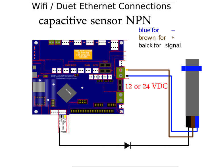
All Duets: Connect the sensor ground wire to a ground pin on the Duet, and the sensor's + power wire to a suitable voltage (typically to VIN because these sensors usually need between 6 and 30V power).
Select mode 5 (P5) in the M558 command. Invert the probe output by prefixing the input pin name (C parameter) with ! character (RRF 3.x), or by adding the I1 parameter (RRF 1.16 to 2.x), in the M558 command
¶ PNP output normally-open inductive or capacitive sensor
If you have a choice between a PNP or a NPN sensor, choose the NPN one because they are simpler to connect to a Duet.
Connect the PNP sensor output/signal wire to one end of a resistor (call this R1), and connect one end of another resistor (call this R2) to GND on the IOx/Z-probe connector. Connect the free ends of R1 and R2 together and to the IN pin of the IOx/Z-probe connector. Connect the PNP sensor V+ to VCC and GND to GND.
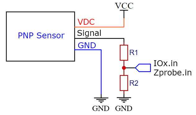
For Duet 3: all IOx.in inputs have a 27K pullup resistor to +3.3V, therefore the value of R2 must be low enough to defeat this. We suggest R2 = 2.2K. Then the value of R1 should be 4.7K to 6.8K if the sensor is powered from +12V; or use 10K to 15K if the sensor is powered from +24V.
For Duet 2 WiFi/Ethernet and Duet 2 Maestro: The values of R1 and R2 should be chosen so that about +3V appears at their junction when triggered. If R2 is 10K, then suitable values of R1 are 30K if the sensor is powered from +12V, and 68K if it is powered from +24V. If you are using the Duet 2 Maestro or the Duet 2 WiFi/ Ethernet revision 1.04 or later, the resistor values are less critical and you can use 10K for both.
Connect the sensor ground wire to Duet ground, and the sensor's + power wire to a suitable voltage (typically to VIN because these sensors usually need between 6 and 30V). An always-on fan connector can be used for this, but make sure you get the polarity right.
Select mode 5 in the M558 command. The signal should not need to be inverted.
Caution! Make quite sure that you connect the sensor output to the IN pin on the Z probe connector. There are 2 versions of the Duet WiFi wiring diagram, and one has the connector reversed with respect to the other. Make sure that the diagram you are using is for the 1.04 revision of the Duet. Connecting the sensor output to the +3.3V pin by mistake will destroy the Duet! Due to the risk of mis-connection, we recommend the wiring method described earlier instead, using two 10K resistors.
Note: on the Duet 2 Maestro and on Duet 2 WiFi/Ethernet revision 1.04 or later, you can instead connect the output of the sensor directly to the IN pin of the Z probe connector because the IN pin is 30V-tolerant. You must still connect a pulldown resistor between IN and GND of the Z probe connector. 10Kohms is a suitable value.
¶ Scanning Z Probe
RRF 3.5.0 and later support LDC1612-based induction probes with an analog output, including the Duet 3 Scanning Z Probe and the Duet 3 Roto Toolboard.
See the hardware pages above for connecting and configuring a Scanning Z Probe. See Scanning Z Probe calibration for usage.
¶ Contact probes using deployable pin
For a detailed description of connecting the following probes, See Connecting a Z probe - BLTouch
¶ BLTouch
See Connecting a Z probe - BLTouch
¶ Wiring the BLTouch
¶ Software setup
See BLTouch configuration here
¶ Creality CR Touch
See Connecting a Z probe - BLTouch
¶ Creality CR Touch wire colours
¶ BIQU MicroProbe V1.0 and V2.0
See Connecting a Z probe - BLTouch
¶ Touch-Mi
See the Touch-Mi section at the bottom of the page here: Connecting a Z probe - BLTouch
¶ TH3D EZABL
See the connection and configuration guide on the TH3D site.
¶ Deployable contact probes
¶ Euclid probe
The Euclid probe is a deployable microswitch probe. For full details on sourcing, assembling, connecting and configuring, see euclidprobe.github.io
¶ Klicky probe
The Klicky probe is a deployable microswitch probe, popular in the Voron community.
Original CAD files and electronics are in the Github repository: github.com/jlas1/Klicky-Probe
Example Klicky RRF configuration and macros are here: github.com/pRINTERnOODLE/RRF-klicky-probe-voron-2.4
Example Klicky AutoZ calibration for RRF here: github.com/pRINTERnOODLE/Auto-Z-calibration-for-RRF-3.3-or-later-and-Klicky-Probe