¶ Introduction
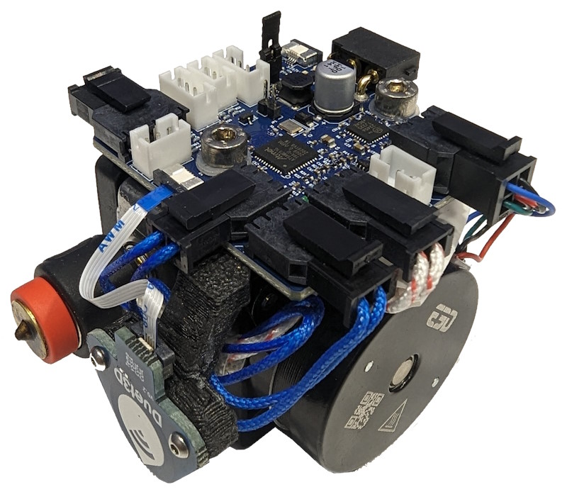
The Duet 3 Roto Toolboard is designed to integrate easily with the E3D Revo Roto extruder and E3D Revo hotends, heaters and temperature sensors. The following connect using the E3D supplied connectors for easy wiring: extruder motor, a 2 or 3-wire heatsink fan, revo heater, thermistor, and secondary temperature sensor. This tool board also provides dedicated connectors for a Duet 3 scanning Z probe coil (supplied as standard) and a Revo Roto specific version of the Duet3D Magnetic Filament Monitor (additional cost option). It also supports a 2, 3 or 4-wire part cooling fan and provides 4 IO ports for endstops, other types of filament monitor and/or Z probe, and a Neopixel LED header.
This reduces the number of wires run to the print head to two power wires and a twisted pair for the CAN-FD bus.
¶ Features
¶ Hardware specification
| Processor | ATSAME51G19A |
| Processor features | 32-bit, 120MHz ARM Cortex M4F, 512KB Flash, 192KB RAM |
| Networking/Comms | CAN-FD interconnect to Duet 3 CAN-FD bus |
| On-board stepper driver | 1 x TMC2240 |
| Stepper driver features | Up to 1.6A1 peak current, microstep interpolation from any setting to x256, stall detection |
| High current outputs | 1 x 3.4A, VIN voltage only (80W at 24V) |
| Thermistor/PT1000 inputs | 3 x inputs, 2 optimised for 100K thermistors and PT1000 sensors, 1 used for the coil temperature on the SZP coil. |
| Medium current outputs | 1 x 4-pin (VIN voltage - designed for part cooling using 2, 3 or 4 pin fans) and 1 x 3-pin (5V compatible with the Roto heatsink cooling fan using 2 or 3 pin fans). Both are PWM-controlled output with tacho input |
| Inputs/Outputs | 3 x on-board I/O connectors for endstop, switches, filament monitor, Z probe. 1 x footprint for a switch or optical proximity sensor |
| Accelerometer | Integrated LIS2DW12 accelerometer |
| Inductive Sensor | Integrated LDC1612 inductive sensor for scanning Z probe |
| Power monitoring | VIN voltage reporting |
1 Maximum current is limited to 1.0A peak in firmware versions earlier than 3.6.0. The Revo Roto extruder motor should not be operated at more than 600mA.
¶ Operating limits
| Stepper driver | Maximum 1.6A peak current, 1.13A RMS1 |
| OUT_1 maximum current | 3.4A |
| Input power voltage | 12V to 32V |
| Power input max current | 5A maximum) |
| Inputs/Outputs | IO_0, IO_1, IO_2 and IO_3 are 30V-tolerant |
| Fuses | None onboard. Use Duet 3 Tool Distribution Board (5A fitted), or if directly connected to a power supply use an inline fuse holder with 5A or lower fuse depending on required current draw. |
| 5V external load | 700mA maximum |
| 3.3V external load | 200mA maximum |
| Maximum ambient temperature | 70°C |
¶ Firmware notes
- Compatible RepRapFirmware versions: RRF 3.5 and later
- Firmware limitations: See Duet 3 with CAN expansion firmware configuration limitations.
¶ Physical properties
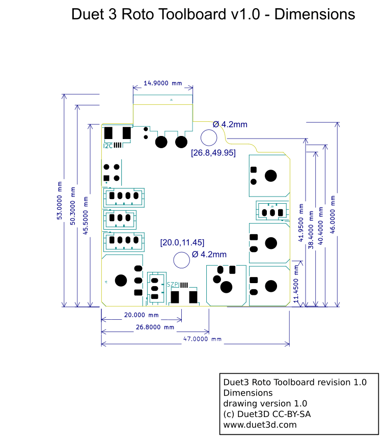
¶ Dimensions
The mounting hole pattern is designed for the sized for the E3D Revo Roto, and it is sized to fit within the side dimensions of the Roto.
¶ 3D model
The STEP file is available on Github here.
¶ Mounting
Mount on the side of the E3D Roto with standoffs/spacers sufficient to ensure none of the components or connectors on the back of the board can touch the metal heatsink or motor of the E3D Revo Roto extruder. The E3D Revo Roto extruder can use either M3 through bolts or M4 self tapping plastic screws for mounting into the mounting holes. See E3D documentation for further information.
A simple spacer design is available here.
The mount for Roto and SZP coil board shown at the top of the page is available here. Note that you may need to adjust the mount to get the SZP coil at the correct height for your nozzle.
¶ Physical connections
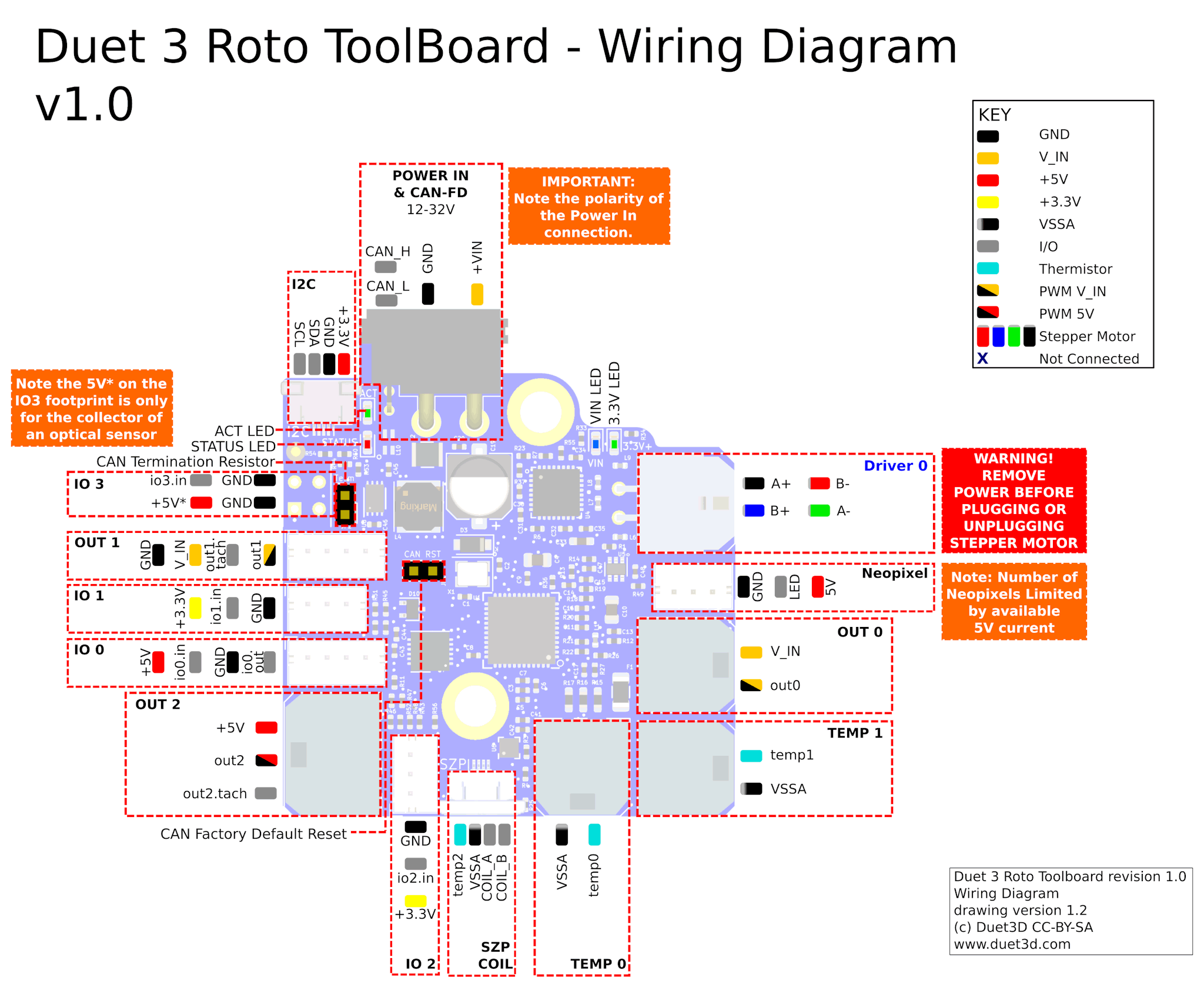
¶ Wiring diagram
¶ Wiring notes
- XT30 2+2: If you do not use a pre-assembled cable then the two CAN pins are best crimped using an engineer PA09 type crimper.
- We recommend connecting the hot end metalwork to ground on the toolboard via a resistor (10k to 1M Ohm), if it is not grounded through its mounting system. This will prevent the hot end building up static charge, which might otherwise occur as filament is extruded and may then flash over to the tool board thermistor input, causing damage.
- The top screw hole is grounded via 100K resistors to provide a path to ground for any static build up in the extruder however because the Roto uses plastic mounting points a short wire will be needed from the mounting hole to a point on the metal extruder heatsink (picture to follow)
¶ Description of Connections
Duet 3 Toolboard 1LC provides the following connectors:
| Connector | Label | Function |
|---|---|---|
| 1 x XT30 2+2 | VIN, GND, CAN_L,CAN_H | Two pins for main VIN and GND along with CAN pins. See CAN section below. |
| 4-pin Molex Microfit 2x2 | DRIVER_0 | Stepper motor connection |
| 3-pin JST PH | LED | Connection for Neopixel LEDs |
| 2-pin Molex Microfit | OUT_0 | High current output intended for an extruder heater, maximum current 3.4A, this is VIN voltage only. There is no flyback diode on this output, so if you connect a high-current inductive load, you must use an external flyback diode. |
| 2-pin Molex Microfit | TEMP_1 | Thermistor or PT1000 input |
| 2-pin Molex Microfit | TEMP_0 | Thermistor or PT1000 input |
| 4-pin 0.5mm pitch FFC | SZP | Connection for a Duet 3 Scanning Z Probe Coil |
| 3-pin JST PH | IO_2 | 3.3V, io2.in, GND, for endstop/ Z-probe/ Filament monitor. Input is 30V-tolerant |
| 3-pin Molex Microfit | OUT_2 | Medium current 5V output intended for, 5V Fan maximum current 0.6A, as part of the overall 5V power budget. Has optional Tacho input. Intended for the heatsink cooling fan on a Revo Roto There is no flyback diode on this output, so if you connect an inductive load, you must use an external flyback diode. |
| 4-pin JST PH | IO_0 | 5V, io0.in, GND, io0.out, for endstop/ Z-probe/ Filament monitor. Input is 30V-tolerant |
| 3-pin JST PH | IO_1 | 3.3V, io1.in, GND, for endstop/ Z-probe/ Filament monitor. Input is 30V-tolerant |
| 4-pin JST PH | OUT_1 | 4-wire fan output (also accepts a 2- or 3-wire fan) intended for use as the print cooling fan. 1A total max current at VIN voltage. This output is protected by a flyback diode. Note When using a 4-wire fan, the tacho reading is valid at all PWM settings. |
| 1 x 4-pin footprint | IO_3 | In version 1.0 this footprint intended for a ITR20001/T reflective optical sensor is reversed however the IO pin can be used for other purposes. Example use case is a tool docking confirmation switch. |
| 4-pin 0.5mm pitch FFC | I2C | For connecting the Revo Roto version of the Duet3D Magnetic Filament Monitor |
¶ LED indications
LEDs are provided to indicate the following:
| Label | Colour | Function |
|---|---|---|
| VIN | Blue | Indicates presence of VIN power (VIN should be externally fused) |
| 3.3V | Green | Indicates presence of 3.3V power from on-board regulator |
| ACT / LED 1 | Green | Indicates activity on the CAN-FD bus |
| STATUS / LED 0 | Red | Status LED. See description below |
Status LED: In normal use, the red LED flashes slowly (approx 1Hz) in sync with the main board to indicate that it has CAN sync, or flashes continuously and rapidly to indicate that it doesn't. It also flashes startup error codes, for example if the bootloader doesn't find valid firmware on the board. For a list of these error codes see CAN_connection basics.
¶ Pin names
For more information on pin names, see Pin Names.
RepRapFirmware 3 uses pin names for user-accessible pins, rather than pin numbers, to communicate with individual pins on the PCB. In RRF 3 no user-accessible pins are defined at startup by default. Pins can be defined for use by a number of gcode commands, eg M574, M558, M950.
The Duet 3 series uses the pin name format "expansion-board-address.pin-name" to identify pins on expansion board, where expansion-board-address is the numeric CAN address of the board. A pin name that does not start with a sequence of decimal digits followed by a period, or that starts with "0." refers to a pin on the Duet 3 Mainboard.
| Function | Pin location | RRF3 Pin name | Notes |
|---|---|---|---|
| Outputs | OUT_0 | out0 | VIN voltage |
| OUT_1 | out1 | VIN voltage | |
| out1.tach | |||
| OUT_2 | out2 | 5V | |
| out2.tach | |||
| Inputs/Outputs | IO_0 | io0.out | 5V power , 3.3V logic on io0.out |
| io0.in | 30V tolerant | ||
| IO_1 | io1.in | 30V tolerant | |
| IO_2 | io2.in | 30V tolerant | |
| IO_3 | io3.in | 30V tolerant. | |
| TEMP_0 | temp0 | ||
| TEMP_1 | temp1 | ||
| TEMP_2 | temp2 | Scanning Z Probe coil thermistor | |
| LED | led |
¶ Input/Output
OUT_0, OUT_1 and OUT_2 are PWM-capable.
The individual IO_x connectors have the following capabilities:
| IO # | UART? | Analog in? | PWM out? | Notes |
|---|---|---|---|---|
| IO_0 | Yes | Yes | Yes | Note: RepRapFirmware does not currently support UART or I2C on Duet 3 expansion/tool boards. |
| IO_1 | No | No | No | Input only, no output pin |
| IO_2 | No | No | No | Input only, no output pin |
| IO_3 | No | No | No | Input only, no output pin |
¶ Power wiring
Supply between 12V and 32V to the appropriate pins of the XT30 2+2 power connector on the Toolboard through a fuse and observing the correct polarity. Inline blade fuse holders are readily available, pick the lowest rated fuse appropriate for your heater and motor current draw.
If you use a relay to control VIN power to the board, ie the power supply is already switched on, and a relay is used to turn on power to the board, you should use an inrush current limiter wired in series with VIN. See the section on Inrush current here.
OUT ports on the mainboard should NOT be used to switch power to expansion or tool boards directly. See the note at the end of the 'inrush current' section at the link above.
¶ CAN
See also CAN Connection Basics.
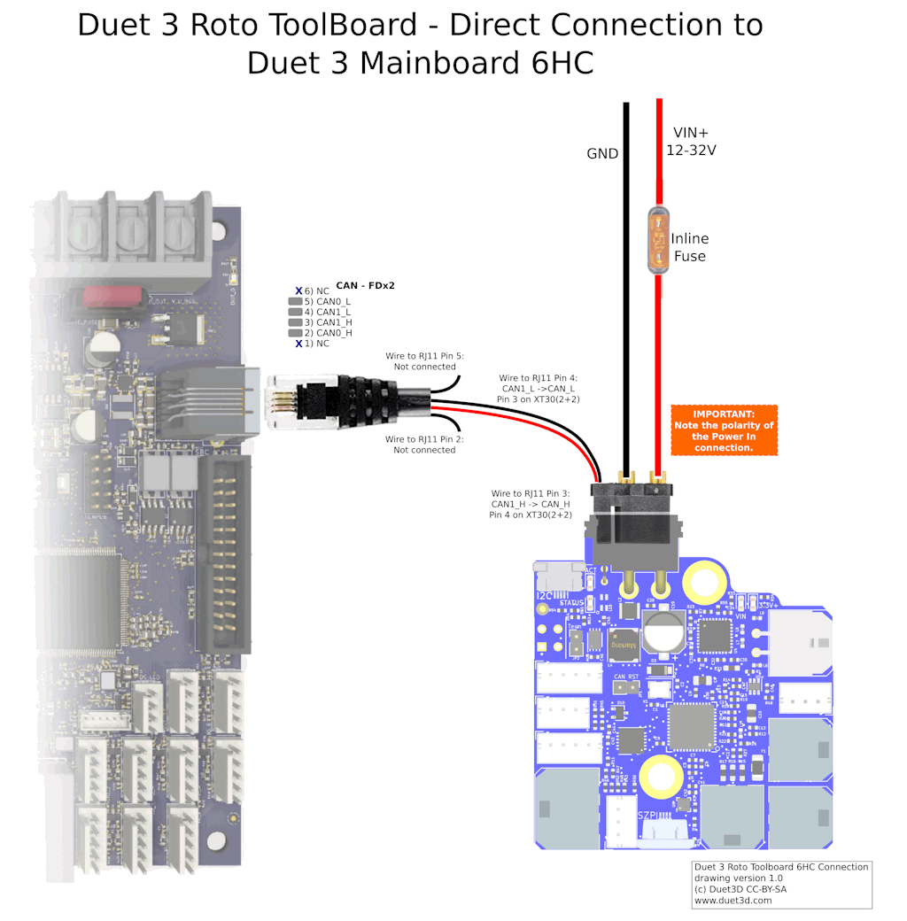
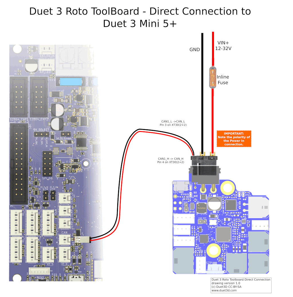
It is possible to connect a Roto Toolboard directly to the Duet 3 Mainboard 6HC, 6XD, Duet 3 Mini 5+, or daisy chain it with other toolboards or any Duet 3 Expansion board.
¶ CAN Connection
The XT30(2+2) pre-wired cables supplied with the boards have different wire colours depending on the wiring batch.
| CAN | Prototpyes and initial V1.0 | Later V1.0 | Moulded connector | Moulded connector (first version) |
|---|---|---|---|---|
| CAN H | Blue | Yellow | Yellow | Yellow |
| CAN L | White | White | White | Green |
Connect the RJ11 socket on the Duet 3 Mainboard 6HC, 6XD or Expansion board, pins 3 and 4 (the middle 2 pins) of the RJ11 connector to pins 4 and 3 of the Toolboard, making sure you get them the right way round i.e. CAN1_H in the Duet to CAN_H on the Toolboard. Don't connect anything to pins 2 and 5 of the RJ11 connector on the Duet.
On the Duet 3 Mini 5+ connect the CAN_FD socket to the 2 CAN pins on the Toolboard, and terminate the other 2 CAN pins.
You can use the Roto tool board with the existing Tool Distribution Board (TDB) like this:
If the cable length from the TDB to the Roto Tool Board is no more than 1m:
- Connect the Roto CAN wires to just two of the pins on the 4-pin connector on the TDB
- Install the bypass jumpers for that port on the TDB
If it's more than 1m:
- Don't install the bypass jumpers for that port on the TDB
- Run two twisted pairs from the 4-pin connector on the TDB to a junction point no more than 1m from the Roto Tool Board, then use the Roto Tool Board cable to connect the Roto Tool Board to that junction.
Multiple Duet 3 Roto toolboards can be connected by daisy chaining the CAN bus connection.
- Ideally the stubs of the bus should be kept as short as possible so the Daisy chaining should be made at or close to the XT30 connector. Connect two wires for CAN_L, and two wires for CAN_H. Ideally these wires should be twisted in two pairs (CAN_H and CAN_L in 1 pair, the second CAN_H and CAN_L in the other pair). One pair then goes to the mainboard or other CAN-FD board earlier in the bus, the other pair goes to the next Roto Toolboard.
- In practice, stubs up to 1m long are usually satisfactory.
Note only the last CAN-FD device on the bus should have the termination resistor fitted.
¶ Terminating resistor
Fit the 2.0mm pitch jumper on the CAN Termination resistor jumper pins if the Roto Toolboard is to be the last device on the CAN_FD bus.
¶ Commissioning
¶ Startup Time
Add the following to your sys/config.g file
It is recommended to add the following to config.g, before any commands that reference any CAN bus connected expansion boards, eg close to the start of config.g
G4 S2 ; wait for expansion boards to start
¶ Set the CAN address
The default CAN address is 121. Changing the CAN address is only necessary if you have another CAN-connected boards with the same CAN address, eg another Duet 3 Toolboard.
All boards in the system must have different CAN addresses. Toolboards are shipped set to a default CAN address of 121. Therefore, if you have more than one Toolboard, only one of them must be powered up and connected to the CAN bus until the address is changed. So disconnect power to all but one of them (you can leave the CAN bus connected if it's easier).
- Send command
M115 B#to verify that the main board can communicate with the Toolboard, where # is the original CAN address (normally 121) - Send command
M952 B# A##where ## is the new address you want to use. We suggest you use addresses starting at 20 for Toolboards. So for the first Toolboard, if your new CAN board was at address 121, sendM952 B121 A20. - Power the system down and up again, or send
M999 B121. This will cause the Toolboard to restart with the new address. - Send command
M122 B20(or whatever address you chose) to verify that you can communicate with the Toolboard at its new address - You can now power up the next Toolboard and commission it in the same way, choosing a different CAN address for it.
¶ Testing communication
Check that you can communicate with the Roto toolboard, by sending
M115 B121
Result should be something like
Duet TOOL1RR firmware version 3.5.2 (2024-06-10 13:24:08)
For a full report, send
M122 B121
The status of the accelerometer and Inductive probe is listed at the end of the report.
¶ LED indications
In normal use, the red LED flashes slowly in sync with the main board to indicate that it has CAN sync, or flashes continuously and rapidly to indicate that it doesn't. It also flashes startup error codes, for example if the bootloader doesn't find valid firmware on the board.
¶ Factory Reset
The board will do a factory reset if you power it up with a 2.0mm jumper fitted to the CAN reset jumper pins. The CAN address will be reset to the default (121), the CAN bus timing will also be reset to default (1Mbps), and the bootloader will request a firmware update.
¶ Updating the firmware
The Roto Toolboard needs RRF v3.5 or later, and the same firmware version must also be running on the Duet 3 mainboard.
Usually, if you update the firmware using the .zip package of the latest release, connected CAN boards will be updated to the same release.
To check versions are the same:
- Send
M115andM115 B#(where # is the Roto Toolboard CAN address, usually 121) to report the firmware version of the mainboard and the Roto Toolboard. - If they are not the same version, download the matching version firmware files from the RepRapFirmware Github repository.
- The firmware filename is Duet3Firmware_TOOLRR.bin and this needs to be uploaded to the /firmware folder of the SD card on the attached SBC, or the SD card in the Duet 3 main board if it is running in standalone mode.
- Update the firmware by using the
M997 B#command, where # is the CAN address of the board.
Factory resetting the board using the CAN reset jumper will cause the bootloader to erase the current firmware, reset the CAN address to the default value of 121, and request the firmware file from the mainboard.
¶ Updating the bootloader
Updating the bootloader is rarely necessary.
Duet 3 expansion boards and tool boards have a bootstrap loader written to the start of flash so that they can load firmware from the main board via CAN. This bootloader may occasionally need to be updated in order to support new features. See Updating the bootloader on Duet 3 expansion and tool boards.
¶ Connecting peripherals
¶ Scanning Z Probe
The Duet 3 Roto Toolboard integrates the same inductive sensing chip as the Duet 3 Scanning Z Probe. It allows for a point mesh of the bed to be built up quickly as no movement in Z is required to read the bed distance, and individual readings happen very quickly.
Here is an example point map form the SZP on a Duet 3 Mainboard 6HC
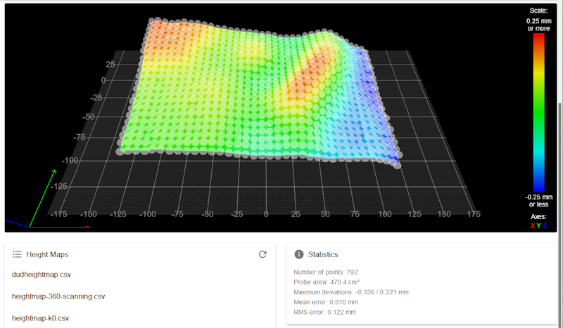
Example mesh of 792 points that took ~20 seconds to produce.
¶ Mounting
The bottom of the SZP coil should be around 1 to 2mm above the tip of the nozzle, so that when scanning the bed the G31 trigger height can be set to around 2mm to avoid the nozzle contacting the bed, while keeping the coil fairly close to the bed.
¶ Configuration
Add the following to your config.g:
; Scanning Z probe
M558 K1 P11 C"121.i2c.ldc1612" F36000 T36000
M308 A"SZP coil" S10 Y"thermistor" P"121.temp2" ; thermistor on coil
- If you change the CAN address, the CAN address in M558 C parameter and M308 P parameter will need to change.
¶ Calibration and usage
For SZP calibration and usage, see Scanning Z Probe calibration
¶ Accelerometer
¶ Configuration
Add the following to your config.g:
M955 P121.0 I10 ; Add accelerometer on Roto with CAN address 121 and specify orientation
See M955 for how to setup and configure the accelerometer.
¶ Orientation
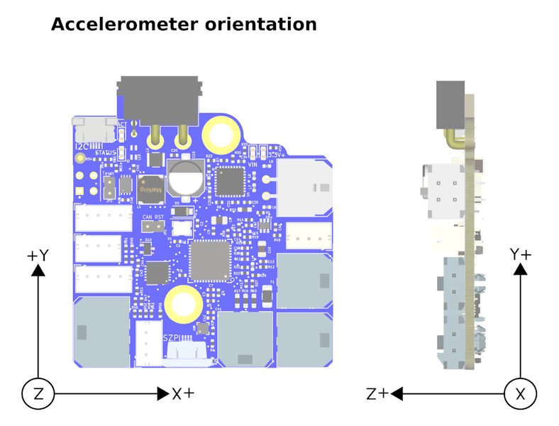
The Duet 3 Roto toolboard has an XYZ arrow to aid orientation of the accelerometer. The Z axis is in the direction of the top face of the board/chip. The default alignment is to align the axes on the board with the axes of your machine, but it may not be possible, so this is configurable in M955.
¶ Calibration and usage
For an overview of using accelerometers to capture data on axis movement see: Connecting an accelerometer
¶ Connecting a BL Touch
The Toolboard supports probe type 8 (unfiltered switch) and 9 (BL Touch). To connect a BL Touch, see table below.
| Toolboard IO_0 connector pin | BLTouch pin | Colour |
|---|---|---|
| io0_out | Control | Orange |
| GND | GND | Black + Brown |
| io0_in | OUT | White |
| 5V_EXT | +5V | Red |
¶ Connecting a filament monitor
For filament monitoring, we recommend using the Duet3D Roto Filament Monitor, which is designed specifically to work with the Roto Toolboard and extruder.
It is also still possible to use the Duet3D Magnetic Filament Monitor
Connector IO_1 or IO2 provides a 3.3V supply and 3.3V input signal level, suitable for a Duet3D Rotating Magnet filament monitor.
See Connecting and configuring a filament runout sensor
¶ PCB Revision History
- Initial version after internal prototypes
