¶ Introduction
There are a number of different versions of the BLTouch, as well as alternative versions made by other manufacturers, e.g. Creality and BIQU/BigTreeTech. All these probes use a physically deployed pin, which senses where the bed is on contact. They require a deployprobe.g and retractprobe.g file to control this, and use M558 P9 to configure the probes.
¶ Supported probes
These instructions, except where stated, cover BLTouch and similar probes:
¶ BLTouch
Manufacturer's website: BLTouch
¶ Creatlity CR Touch
Manufacturer's website: Creality CR Touch
¶ BIQU MicroProbe
Manufacturer's website: BIQU MicroProbe V1.0 and V2.0
¶ TH3D EZABL
Manufacturer's website: TH3D EZABL
See the connection and configuration guide on the TH3D site.
¶ Touch-Mi
Manufacturer's website: Auto Leveling sensor "Touch-MI"
See the Touch-Mi section at the bottom of the page.
¶ Pinout and wire colours
CHECK YOUR WIRING!
If using a clone BLTouch, or one supplied with a manufacturer's kit, the wiring colours may not match those listed below, which are correct for genuine BLTouch kit from www.antclabs.com. However, the actual pinout of the connector on the probe's PCB is the same, as far as we can tell. See information below.
¶ BLTouch pinout and wire colours

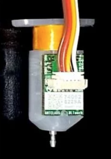
When viewed from the side with the PCB, as above, the pinout and wire colours for a genuine BLTouch should be, from LEFT to RIGHT:
| PCB pinout | GND (Left) | +5V (Left mid) | Control (Middle) | GND (Right mid) | Out (Right) |
|---|---|---|---|---|---|
| Genuine BLTouch wiring | Brown | Red | Yellow | Black | White |
For clone and BLTouch kits supplied by other companies, e.g. Creality, the wiring colours may be different. For example, we have seen:
| PCB pinout (Left to Right) | GND | +5V | Control | GND | Out |
|---|---|---|---|---|---|
| Creality kit (some versions) | White | Black | Yellow | Blue | Red |
| Creality kit (most common) | White | Black | Yellow | Red | Blue |
i.e. the wiring colour is reversed, sometimes with different colours for the last two pins.
If in doubt, check the orientation of the connector on the probe PCB by using a multimeter to test for a connection between the GND pins (pins 1 and 4, or 2 and 5 if reversed). This should make it clear the order of the pins on the PCB. Then note the colour of the wire that connects to each pin.
¶ BIQU MicroProbe
The BIQU MicroProbe is physically a drop-in replacement for the BLTouch, so the above information should apply. Note that it is configured differently, and there is a difference between the V1 and V2 probe. See the BTT Microprobe tab of the TeamGloomy instructions here for configuration.
¶ Creality CR Touch wire colours
Creality CR Touch kits also use a cable with different colours.

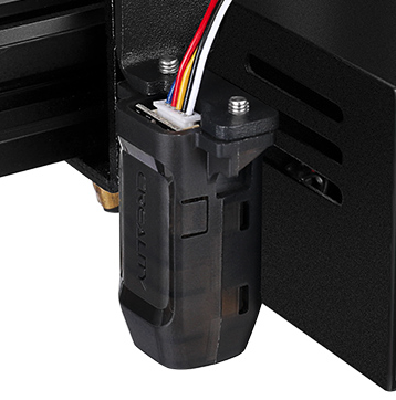
When viewed from the side with the Creality logo, as above, the pinout should be, LEFT to RIGHT:
| PCB pinout (Left to Right) | Out | GND | Control | +5V | GND |
|---|---|---|---|---|---|
| Creality CR Touch (most common order seen) | Blue | Red | Yellow | Black | White |
This is reversed from the BLTouch, mainly because you are looking at the back of the probe PCB, rather than the front.
If in doubt, check the orientation of the connector on the probe PCB by using a multimeter to test for a connection between the GND pins (pins 2 and 5, or 1 and 4 if reversed). This should make it clear the order of the pins on the PCB. Then note the colour of the wire that connects to each pin.
¶ Wiring
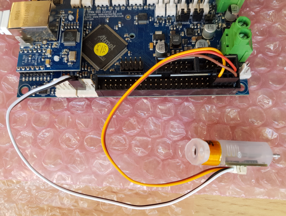
Connect the BLTouch to a PWM-capable IO header. For more information on pin header capability, see the 'Input/Output' section of the hardware overview of the board you are connecting the BLTouch to.
| Duet 3 board (link to hardware overview) |
PWM-capable IO headers |
|---|---|
| Duet 3 MB6HC | IO_4, IO_5 or IO_7 (v0.6 and later) |
| Duet 3 6XD | IO_4 or IO_7 |
| Duet 3 Mini 5+ | IO_1, IO_2 or IO_3 |
| Duet 3 Toolboard 1LC | IO_0 |
| Duet 3 Expansion 3HC | IO_1 or IO_4 |
| Duet 3 Expansion 1XD | IO_0 or IO_2 |
Connect as follows:
| IO_[n] | connector pin | BLTouch pin Colour |
|---|---|---|
| 3.3V | - | - |
| IN | OUT | White |
| GND | GND | Black + (Brown or Blue) |
| OUT | Control | Orange or Yellow |
| +5V | +5V | Red |
With older BLTouch (before V3.0), the output is 5V by default. All Duet 3 IO_inputs are 30V tolerant, so it doesn't matter whether you reduce the output of the BLTouch to 3.3V or leave it at 5V.
Connect the BLTouch as follows:
| Duet Z Probe connector pin | Duet expansion connector pin | BLTouch pin | Colour | |
|---|---|---|---|---|
| IN | Out | White |  |
|
| GND | GND | Black | ||
| 5V (pin 1) | +5V | Red | ||
| Heater3 (pin 8) | Control | Orange or Yellow | ||
| GND (pin 2) | GND | Brown or Blue | ||
¶ For all Duet 2 WiFi/Ethernet boards prior to version 1.04
If you have the older BLTouch (before V3.0), the output is 5V by default. However, the Z probe input on Duet 2 WiFi/Ethernet boards prior to version 1.04 is not 5V tolerant.
- Either: Connect a 240 ohm resistor between Probe GND and Probe IN.
- Or: Cut the PCB trace on the BLTouch to reduce the output to 3.3V as described in the instructions for your BLTouch version. See https://www.antclabs.com/
This does not apply to other probes, eg BLTouch V3.0 and later, BIQU Microprobe, Creality CR Touch, which output 3.3V by default. Though be aware some can be changed to 5V output.
Also does not apply to Duet 2 WiFi/Ethernet rev 1.04 and later as the Z probe input is 30V tolerant, so it doesn't matter whether you reduce the output of the probe to 3.3V or leave it at 5V.
On the Duex and EBoB, connect the BLTouch GND, +5V, and control wires to an available three-pin PWM output. Connect the BLTouch out and GND wires to the Duet Z Probe connector.
On the Duex, heater outputs and PWM outputs share the same signal, ie the same signal controls PWM1 as e2heat, PWM2 is shared with e3heat, PWM3 is shared with e4heat, etc. You need to use a PWM connector whose matching heater is free.
If you have a Duex v0.9 or v0.9a board, check that you have a jumper on the "5V AUX JUMPER SELECT PINS" between the 5V AUX and 5V INT pins. See this thread on the forum for details.
Connect the BLTouch as follows:
| Duet Z Probe connector pin | DueX/EBoB PWM connector pin | BLTouch pin | Colour |
|---|---|---|---|
| IN | - | Out | White |
| GND | - | GND | Black |
| - | GND | GND | Brown or blue |
| - | +5V AUX | +5V | Red |
| - | E#_PWM or HEATER#_PWM | Control | Orange or yellow |
¶ For all Duet 2 WiFi/Ethernet boards prior to version 1.04
If you have the older BLTouch (before V3.0), the output is 5V by default. However, the Z probe input on Duet 2 WiFi/Ethernet boards prior to version 1.04 is not 5V tolerant.
- Either: Connect a 240 ohm resistor between Probe GND and Probe IN.
- Or: Cut the PCB trace on the BLTouch to reduce the output to 3.3V as described in the instructions for your BLTouch version. See https://www.antclabs.com/
This does not apply to other probes, eg BLTouch V3.0 and later, BIQU Microprobe, Creality CR Touch, which output 3.3V by default. Though be aware some can be changed to 5V output.
Also does not apply to Duet 2 WiFi/Ethernet rev 1.04 and later as the Z probe input is 30V tolerant, so it doesn't matter whether you reduce the output of the probe to 3.3V or leave it at 5V.
Connect the BLTouch to the Z probe connector as follows:
| Duet Z Probe connector pin | BLTouch pin | Colour | |
|---|---|---|---|
| IN | Out | White |  |
| GND | GND | Black + (Brown or Blue) | |
| MOD | Control | Orange or Yellow | |
| 3.3V | - | - | |
| +5V | +5V | Red | |
With older BLTouch (before V3.0), the output is 5V by default. The Z probe input on the Duet 2 Maestro is 30V tolerant, so it doesn't matter whether you reduce the output of the BLTouch to 3.3V or leave it at 5V.
¶ Configuration
Note: The BIQU/BTT Microprobe is configured differently from the BLTouch, and there is a difference between the V1 and V2 probe. See the BTT Microprobe tab of the TeamGloomy instructions here for configuration.
¶ Software setup
- Identify the name of the output pin that you connected the control input of the BLTouch to.
- On Duet 3 it is the io[n].out pin, eg io7.out
- On a Duet 2 WiFi/Ethernet without an attached expansion board, it will be one of exp.heater3 thru exp.heater7
- If you have a DueX attached, one of duex.pwm1 thru duex.pwm5
- If you have a Expansion Breakout Board, it's !exp.heater6 or !exp.heater7 ('!' inverts the output, and is needed).
- On a Duet Maestro it is zprobe.mod.
If you use one of these pin names, you will not need to invert the output (except on BoB).
- Create a GPIO/Servo pin index using your chosen control pin, for example:
M950 S0 C"io7.out" ; Duet 3 MB6HC
M950 S0 C"io3.out" ; Duet 3 Mini 5+
M950 S0 C"exp.heater3" ; Duet 2 WiFi/Ethernet
M950 S0 C"duex.pwm1" ; Duet 2 WiFi/Ethernet + DueX2/5
M950 S0 C"!exp.heater6" ; Duet 2 WiFi/Ethernet + BoB
M950 S0 C"zprobe.mod" ; Duet 2 Maestro
The above examples use GPIO/Servo index 0. If you have other GPIO/Servo pins already configured, change the index to an available number.
- The Z probe input pin will be:
- io[n].in pin on Duet 3 eg io7.in
- ^zprobe.in on a Duet 2
You only need to enable the pullup resistor, using the ^ character in front of the pin name, on Duet 2 when using the zprobe.in.
Do not enable the pullup resistor if you are using a Duet 3 input, or a Duet 2 endstop input.
- In your M558 command, specify probe type 9 and the input pin, for example:
M558 P9 C"io7.in" H5 F120 T6000  ; Duet 3 MB6HC
M558 P9 C"io3.in" H5 F120 T6000 ; Duet 3 Mini 5+
M558 P9 C"^zprobe.in" H5 F120 T6000 ; Duet 2 WiFi/Ethernet, DueX2/5
M558 P9 C"^zprobe.in" H5 F120 T6000 ; Duet 2 Maestro
- Set up the probe offsets, trigger height and trigger value in G31:
G31 X20 Y0 Z3.3 P25
In this example the trigger height is 3.3mm (you will need to measure it) and the probe is offset from the head reference point by 20mm in the +X direction.
- Create a deployprobe.g file (in the /sys folder of the SD card) it should contain the following single command:
M280 P0 S10
- 'P0' is the GPIO/Servo index 0, defined by M950 S0 earlier. If you have changed the GPIO/servo index, change the P parameter in M280 to match.
- 'S10' is the signal sent to the BLTouch to deploy the probe.
- Create a retractprobe.g file (in the /sys folder of the SD card) it should contain the following single command:
M280 P0 S90
- 'P0' is the GPIO/Servo index 0, defined by M950 S0 earlier. If you have changed the GPIO/servo index, change the P parameter in M280 to match.
- 'S90' is the signal sent to the BLTouch to retract the probe.
¶ Commissioning & Testing
To test the setup with the nozzle maybe a 100mm up from the bed you can check if the trigger signal is reaching the Duet by attempting to extend the pin by using the following command:
M280 P0 S10
If all is well the web interface should report a value of ”0” or "N/A" in the Z probe column when the pin is extended. You can then lightly touch the extended probe pin to check that the value in the Z probe Column changes to “1000”
You can retract the pin again with
M280 P0 S90
the above two commands are also what should be in /sys/deployprobe.g and /sys/retractprobe.g, respectively. Test these are working correctly by sending M401 to deploy the probe, and M402 to retract the probe.
Before trying to home (and smashing your hot end into the bed repeatedly when it doesn't work), conduct the tests and calibrate the Z probe as described here; see Test and calibrate the Z probe
¶ Software setup (Duet 2 WiFi/Ethernet running RepRapFirmware 2)
Important: In the M280 commands in the following, leave out the I1 parameter if the BLTouch is connected to a servo output on a DueX board.
- In your software config.g file input the following G-Code commands to allow the setup to work:
M307 H3 A-1 C-1 D-1
M558 P9 H5 F100 T2000
G31 X0 Y0 Z0 P25
- Important: mode 9 is supported in firmware 1.21 and later only. If you are using earlier firmware, replace P9 in the M558 command by P5.
- In the G31 command the X and Y are the offset of the sensor in relation to the nozzle (so input your own) the number for Z is the trigger height (read on for this). This is the height that is obtained from reading the height the nozzle is from the bed when the sensor pin contacts the bed and retracts, P is the signal threshold.
- Ensure in your config-override.g file (in the /sys folder of the SD card) does not contain an M307 H3 command that overrides the above configuration.
- In the M280 commands (see below), you must invert the servo signal using “I1” in the M280 commands if you connect the BLTouch servo input to the expansion header pins, but not if you connect the BLTouch servo input to a Duex.
- Create a deployprobe.g file (in the /sys folder of the SD card) it should contain the following single command:
M280 P3 S10 I1
See the important note earlier about including the I1 parameter or not.
- Create a retractprobe.g file (in the /sys folder of the SD card) it should contain the following single command:
M280 P3 S90 I1
¶ Software setup (Duet 2 Maestro running RepRapFirmware 2)
As for the Duet 2 WiFi/Ethernet with the following changes:
- The M307 line is not required
- In all M280 commands, use P64 instead of P3, and leave out the I1. This applies to the following section too.
¶ Commissioning & Testing (RepRapFirmware 2)
To test the setup with the nozzle maybe a 100mm up from the bed you can check if the trigger signal is reaching the Duet by attempting to extend the pin by using the following command:
M280 P3 S10 I1
Then put the Sensor in to test mode by inputting the following command:
M280 P3 S120 I1
If all is well the web interface should report a value of ”0” in the Z probe column when the pin is extended. You can then lightly touch the extended probe pin to check that the pin retracts, the value in the Z probe Column should change to “1000”
The BL Touch will continue to cycle deploy in the test mode, to end the test mode enter:
M280 P3 S160 I1
Test deployprobe.g and retractprobe.g are working correctly by sending M401 to deploy the probe, and M402 to retract the probe.
Before trying to home (and smashing your hot end into the bed repeatedly when it doesn't work), conduct the tests and calibrate the Z probe as described here; see Test and calibrate the Z probe
¶ Troubleshooting
¶ Touch-Mi
The Touch-Mi is based on an IR end stop with a metal pin for probing in the z direction. While the probe is documented to run at 5v, it can also be run at 3.3v (this has been confirmed with hotends.fr, the manufacturer of the Touch MI).
¶ Wiring
¶ Duet 3
Connect the Touch-Mi to an IO header. Connect the red wire to 3.3V, the black wire to GND, and the yellow wire to io[x].in, where [x] is the chosen IO header.
¶ Duet 2
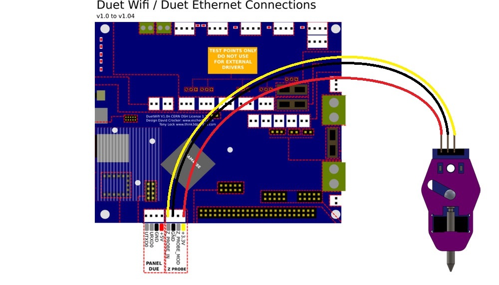
The Touch-Mi can be connected to the z probe headers of the Duet 2 board as shown below.
Alternately, you can connect the Touch-Mi to a 5V pin (from the PanelDue header or from the expansion header) for VCC and to the E0 endstop for GND and IN (use the outer pins of the E0 endstop header).
¶ Configuration
The Touch-Mi probe is active low. If connected to the z probe port, the M558 configuration should be like this:
; RRF 3
M558 K0 P8 C"io2.in" H10 F120 T4000    ; Duet 3
M558 K0 P8 C"zprobe.in" H10 F120 T4000 ; Duet 2

; RRF 2
M558 P8 F500 H10 I0 T4000 ; Duet 2
H should be at least 3mm, but during the first runs with a new probe (or after changing out your bed), it is advisable to increase H to a safe diving height. The example sets diving height at a comfortable triple minimum distance, and you can reduce H if you are sure the probing pin won't catch after deploying and/or drag across the bed surface during moves.
Also, set trigger value, nozzle offset, trigger offset using G31:
G31 P500 Xnnn Ynnn Znnn
See the calibration section for a method to determine z offset.
The Touch-Mi is deployment is triggered via a magnet. As this magnet is usually installed so it triggers deployment by hitting X0 or X(max), the probing should be at a distance to X0/X(max). As such, it is recommended your mesh definition happens a bit inside the outer edges of your bed parameters. For a 220x220 size bed, M557 could look like this for a 6x6 grid:
M557 X10:210 Y10:210 S40
M557, M558 and G31 P... as described here should be added to config.g.
¶ Touch-Mi macros
deployprobe.g:
; deployprobe.g
; this is a manual probe deployment by touching the Touch-Mi Probe
; with the magnet  included.

G91                       ; relative positioning
G1 Z7 F600 S2             ; lift Z relative to current position
G90                       ; absolute positioning
; G1 X0 F1800               ; move X to zero
M291 P"Trigger Magnet" S3 ; prompt for magnet action
retractprobe.g
; retractprobe.g
G0 Z0.5             ; dive to retract probe with magnetic ball bearing
homez.g
; homez.g
; called to home the Z axis

G91                ; relative positioning
G90                ; absoute position
M401               ; deploy probe
G1 X163 Y129 F1800 ; move to middle of bed plus probe offsets
G30                ; home z0
M402               ; retract probe
homeall.z
; homeall.g
; called to home all axes

G91                      ; relative positioning
G1 H1 X-225 Y-225 F1800  ; move quickly to X and Y axis endstops and stop there (first pass)
G1 X5 Y5 F6000           ; go back a few mm
G1 H1 X-225 Y-225 F360   ; move slowly to X and Y axis endstops once more (second pass)
G90                      ; absoute position
M401                     ; deploy probe
G1 X163 Y129 F1800       ; move to middle of bed plus probe offsets
G30                      ; home z0
M402                     ; retract probe
¶ Calibrating the Touch-Mi
-
Calibrate nozzle to zero manually (paper test).
-
Set Z to zero (
G92 Z0) -
Lift nozzle by 5 to 10 mm (
G0 Z10) -
Determine probe trigger height (
G30 S-1) and note the result shown on the G-Code console. -
Repeat steps 3 and 4 a couple times to ensure the result of
G30 S-1has acceptable repeatability (variance smaller or equal to 0.03mm). Note the average of these repeated measurements. -
Set the trigger height in G31 in your config.g
