¶ Overview
Input shaping describes a set of algorithms to reduce ringing frequencies that inevitably occur due to hardware factors in 3D printers. In order to isolate what frequencies affect a machine the most, an accelerometer may be used. Note that revision 1.1 and newer of the Duet 3 Toolboard 1LC boards also come with an embedded accelerometer.
¶ Plugin installation
Starting from DWC 3.4 the Input Shaping plugin can be installed to fine-tune input shaper parameters using an accelerometer.
To install the Input Shaping plugin, download the latest release version for your RepRapFirmware version from the Duet3D Github repository as a .zip file, without unpacking it, and upload it using the Upload&Start button on DWC without unpacking the file first. After this, you should see the Plugins category with a new Input Shaping item in the main menu on the left:

Before you can start recording samples, you must have an accelerometer connected and configured (see also M955). If you already know the frequencies you wish to cancel out, an accelerometer is not required.
¶ Determining ringing frequencies
The Input Shaping plugin allows you collect motion profiles easily to show which frequencies are excited during a long move.
To begin, navigate to the Input Shaping section and make sure the currently configured input shaper is set to None. If it isn't set to None, you can click on apply next to it.
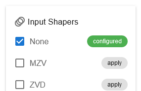
This way, you can get a base profile that does not have any frequency reduction applied.
¶ Recording a new profile
Next, press Record Motion Profile to open a wizard that will guide you through the process of data collection. If you have a valid setup with at least one accelerometer, the first page should look like this:
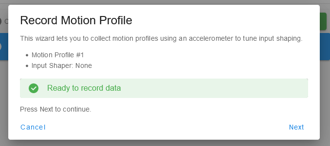
If an invalid configuration is detected, this page will display what is wrong. Move on to the next page when ready.
¶ Move configuration
On the next page you can set up the moves for data collecting among a few other things.
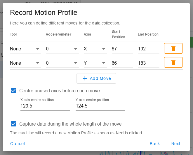
These settings include the following items:
¶ Moves to perform
By default the plugin defines two individual moves for X and Y. Either during or after each move is performed, the plugin records accelerometer profiles to determine a frequency response (see also the last checkbox). You can define multiple moves as well.
It is recommended to configure only those axes that actually have an accelerometer fitted. Assuming you have a bed slinger and the accelerometer is only mounted on X (print head), record only moves on the X axis. If you want to use the embedded accelerometer from a TOOL1LC, it is advised to select the corresponding tool as well.
¶ Axis centres
Since the highest ringing amplitude is likely to occur at the centre of an axis, the wizard proposes to move each of the unused axes to the centre position before data collection is performed. You can choose if you want to move the axes that are not affected by a sampling move to the centre position or not.
¶ Capture data either before or after a move
Since a sampling move can introduce low-frequency responses (< 10Hz), you can choose if you want to record data either while the move is being performed (default) or after the move has finished.
¶ Data collection
When Next is clicked, data collection commences.
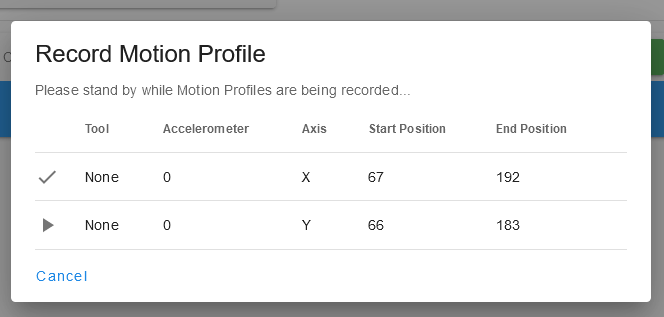
You can cancel data collection at any time by clicking Cancel or by clicking on the grey backdrop. The wizard will let you know when the data collection is complete:
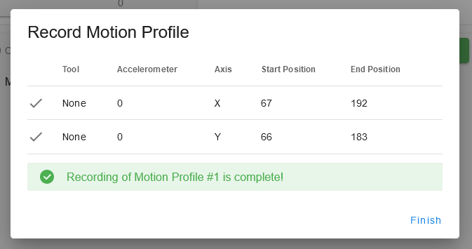
Every time you collect a new motion profile, the corresponding counter is increased. Note that the wizard saves your last input values so you can record multiple profiles easily with the same preset but different input shaper parameters.
¶ Data evaluation
When the base profile is complete, you can see a new item in the list on the left. When you click on an item, all the accelerometer files are automatically downloaded, analysed, and displayed:
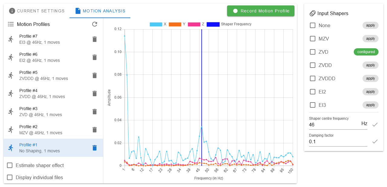
- Note that the profiles contain only a single move here because the acelerometer was only fitted to the print head (aka X)
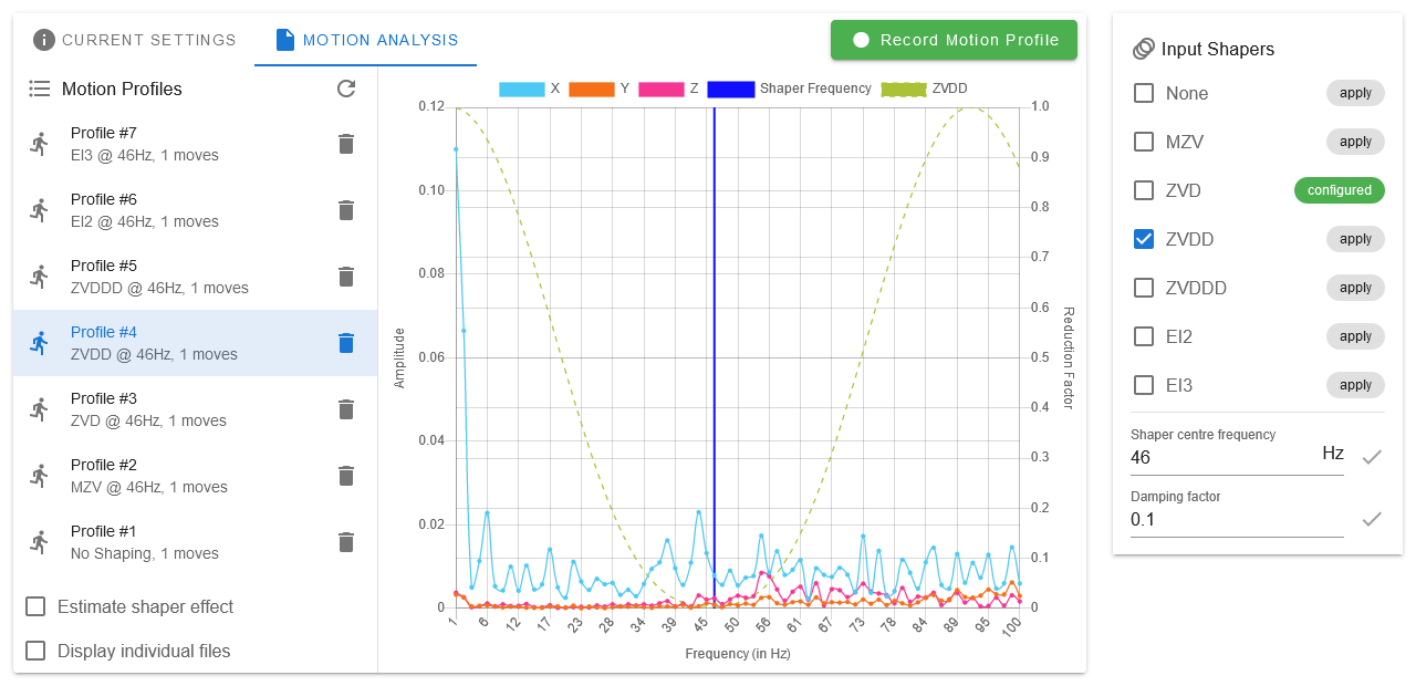
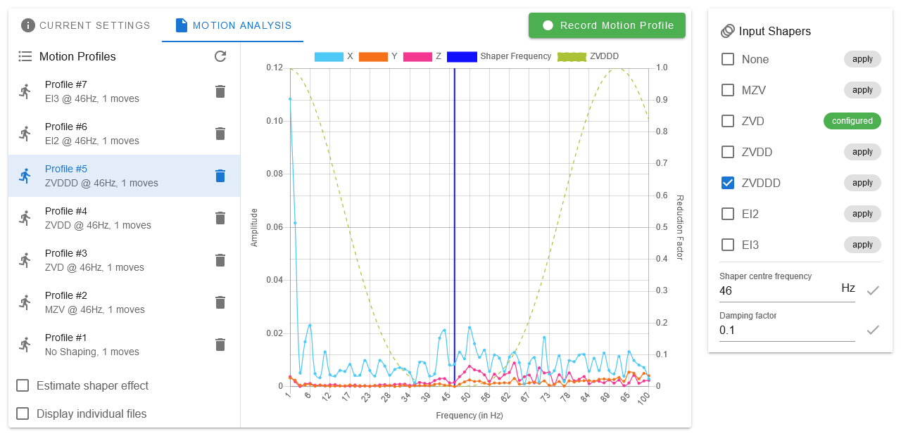
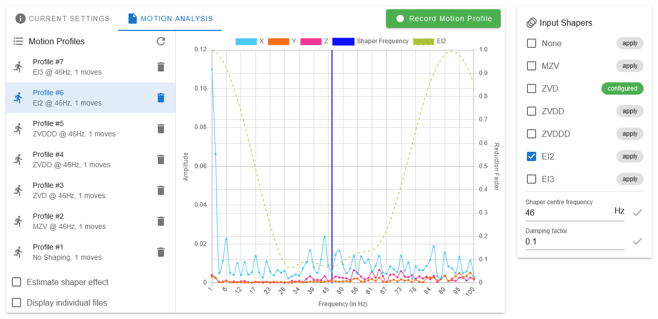
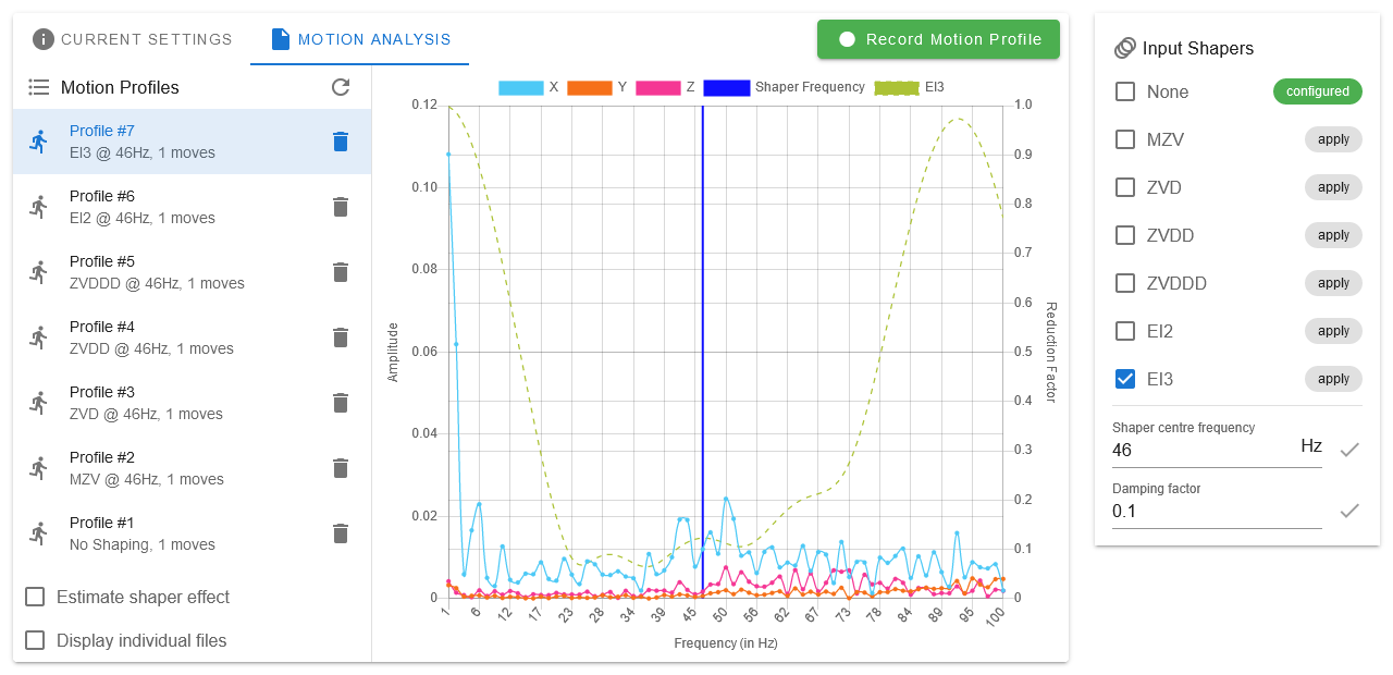
Usually you can ignore frequencies below 10Hz because they originate from the move itself. When you look at the other frequencies, you can easily detect the greatest peak at ~46Hz. This means this is the frequency that should be reduced using input shaping. In order to do so, you can change the shaper centre frequency in the input box on the right (arrow keys are supported as well).
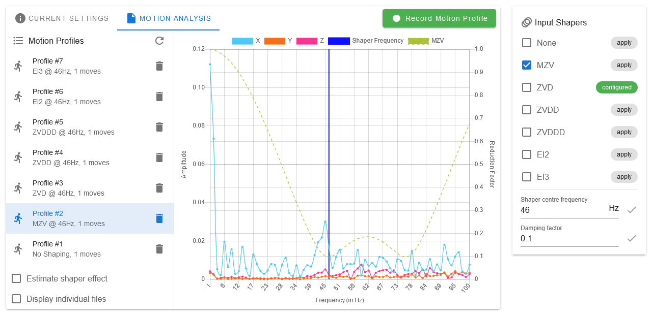
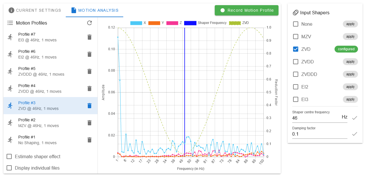
So, as the next step, we can compare the different input shapers with the centre frequency set to 46Hz. To apply a given input shaper, just click apply next to every item on the right. You can then repeat the data collection step for each input shaper. To see the estimated reduction factor of each input shaper, you can check it as well.
Once the data collection is complete, you can compare the results:
¶ Data interpretation
- Depending on your setup you might see occasional data overflows. If they occur, you can delete the last profile using the trash can icon and record a new profile again.
By comparing the different motion profiles, you can see that the greatest frequency reduction is achieved using the ZVD input shaper. To make this configuration persistent, M593 can be added/updated in config.g:
M593 P"zvd" F46
Since ZVD(D/DD) shapers are performed relatively quickly, they are generally preferred over EI2/EI3, although they do not cover as many frequencies.
If you have only one accelerometer and it is mounted to a single axis, you can repeat this whole recording step once the accelerometer is mounted on the other axis.
¶ Multiple ringing frequencies
RepRapFirmware does not support individual axis shaper configurations because that could lead to undesired behaviour on XY moves. For this reason we recommend choosing an input shaper which covers both ringing frequencies.
If you get two peaks at two individual frequencies, you should configure an input shaper that covers both. When you go to the Current Settings tab, you can see the estimatated damping at a given frequency for each checked input shaper.
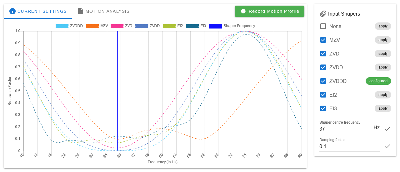
For example if you see ringing at 32Hz and 42Hz, you could choose ZVDDD at 37Hz to achieve reasonable input shaping which covers both frequencies.