¶ Introduction
RepRapFirmware 3.3 and later include support for connecting accelerometers. The primary purpose is to identify the ringing frequencies of the mechanics so that input shaping can be tuned to reducing ringing.
¶ Supported hardware
¶ Supported accelerometers
RRF 3.3 supports one type of accelerometer, the LIS3DH. We chose this chip because of its low cost and because it provides a mechanism to read all the data stored in its FIFO in a single block command.
RRF 3.4 added support for the LIS3DSH (note the extra S). Connection via SPI and configuration are exactly the same as for the LIS3DH. Compared to the LIS3DH, the LIS3DSH has higher resolution, more convenient sampling rates, and produces a cleaner signal.
RRF 3.5.0 added support for the LIS2DW12. Connection via SPI and configuration are exactly the same as for the LIS3DH/LIS3DSH. The LIS2DW12 is similar in performance to the LIS3DSH.
¶ Duet mainboards
Duet 3 mainboards, Duet 2 WiFi/Ethernet and Duet 2 Maestro support a directly-connected accelerometer.
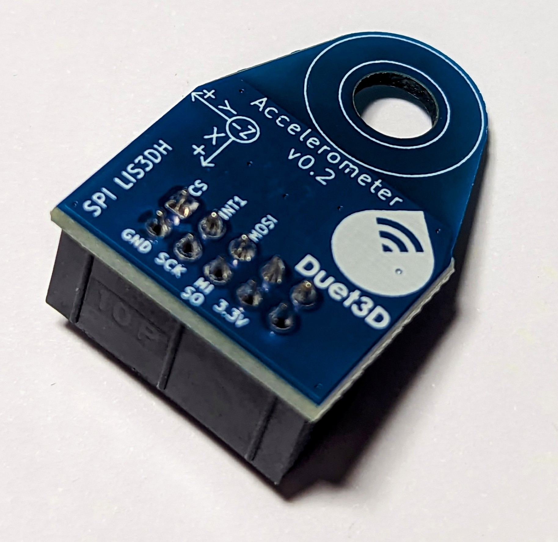
- Duet3D Accelerometer, using the LIS3DH or LIS2DW, designed to plug into the SPI Daughterboard header on Duet 2 and 3 mainboards.
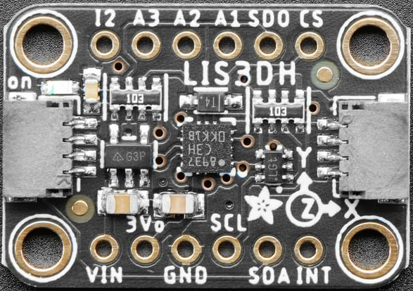
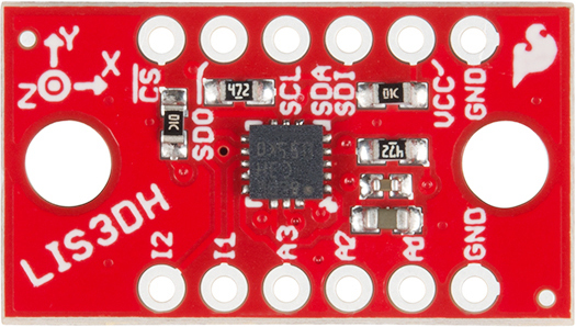
- Accelerometer boards using the LIS3DH / LIS3DSH / LIS2DW are available from eBay, Amazon and other retailers such as SparkFun, Adafruit, Digikey The Pi Hut (UK), HobbyTronics (UK) and Pimoroni (UK). The Adafruit and SparkFun boards are also available from Digikey. There are two different versions of the Adafruit LIS3DH board; either can be used.
Duet 3 mainboards also support CAN-bus connected boards with built-in accelerometers. Duet3D have a number of boards with a built-in accelerometer:
- Duet 3 Toolboard 1LC (v1.1 and later) Duet 3 CAN-FD toolboard with LIS3DH accelerometer.
- Duet 3 Roto Toolboard Duet 3 CAN-FD toolboard with LIS2DW accelerometer.
- Duet 3 Scanning Z Probe Duet 3 CAN-FD scanning Z probe board with LIS2DW accelerometer.
Duet 3 mainboards also support CAN-bus connected boards with wired accelerometers.
- Sammy-C21 with a wired accelerometer.
¶ Limitations
- In RRF 3.3, data collection from accelerometers is currently only available when running the Duet in standalone mode. In RRF 3.4 and later, data can be collected when running in SBC mode too.
- Use of an accelerometer as a Z probe is not currently supported.
¶ Wiring
To use a direct connection, connect the accelerometer SDA (also called MOSI), SDO (also called MISO), SCL and GND pins to the corresponding pins on the SPI/temperature daughterboard (TEMP_DB) connector. You can also pick up +3.3V on the daughterboard connector to feed to the VCC pin of the accelerometer.
Two further signals must be connected on the accelerometer breakout board: CS and INT1. The INT1 pin must be connected to a Duet pin with interrupt capability. The CS pin should be separated from other signal wires if possible because it is sensitive to interference, especially when using a Duet 3 Mini or Duet 3 MB6HC (see note in 'Wiring recommendations').
¶ Wiring schemes
There are two basic wiring schemes:
- All wires connect to the temperature daughterboard connector (supported by all Duet mainboards)
- CS and INT1 wires are connected to IO_n.out and IO_n.in of any IO connector, all other wires connect to the TEMP_DB connector.
This is supported by all Duet 3 mainboards, useful if there are signalling problems, or if you have the maximum number of temperature daughterboards and want to have the accelerometer permanently connected.
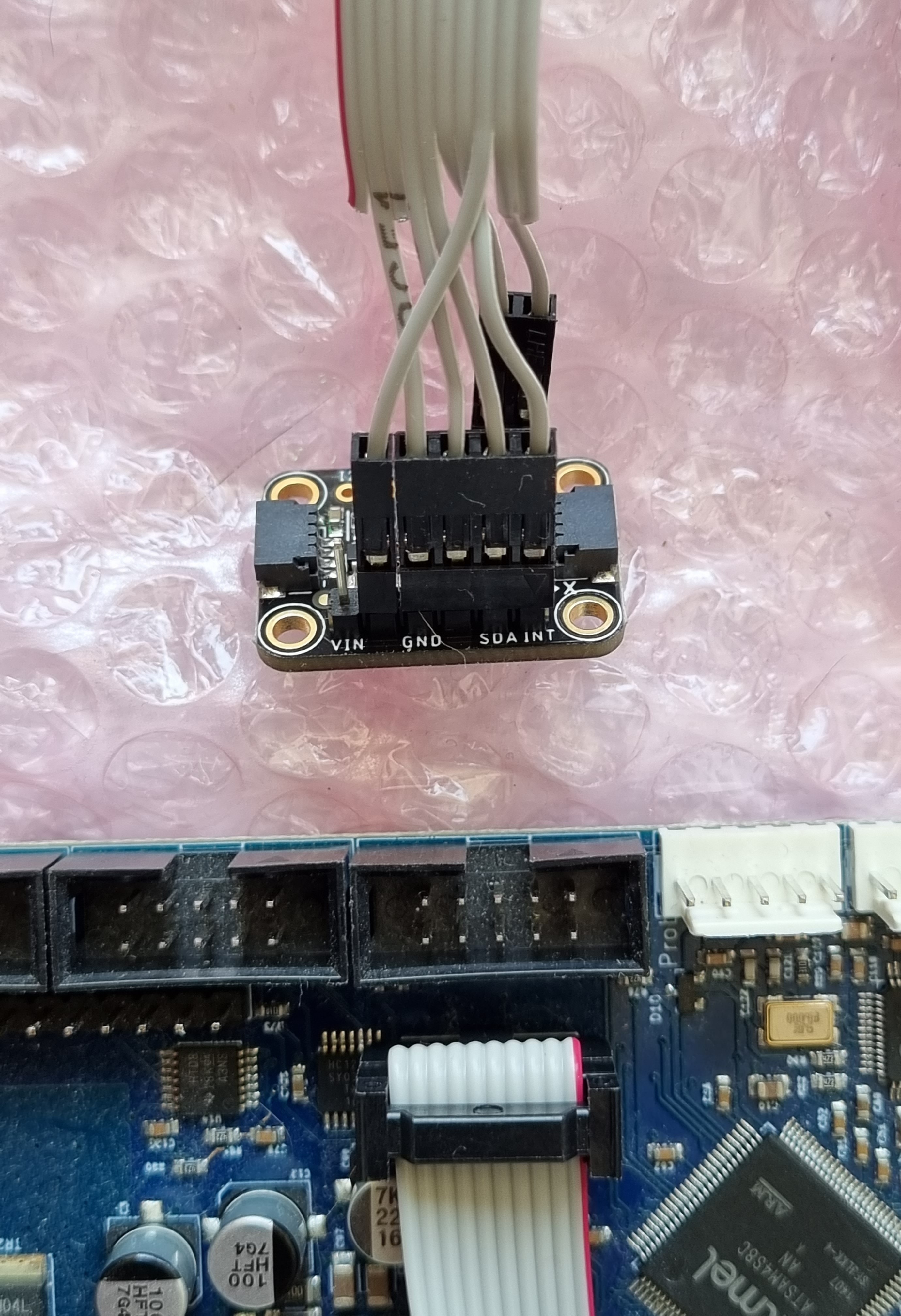
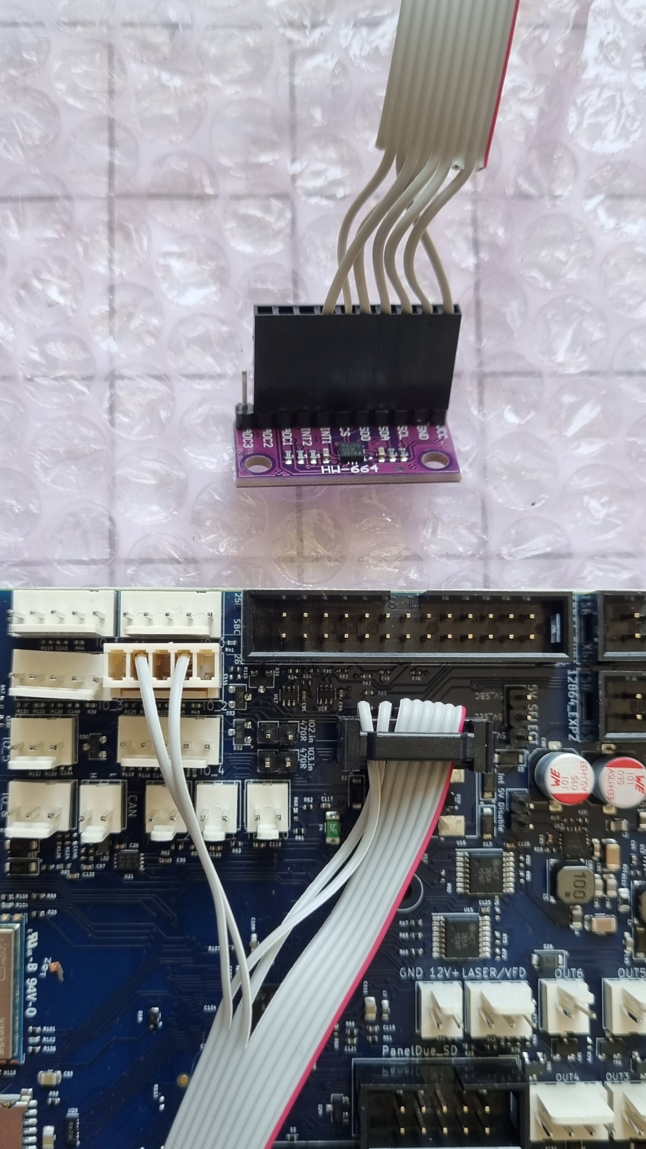
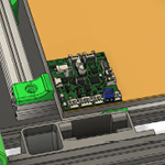
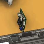
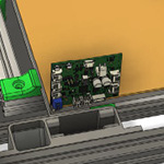
Note: the pictures above show an alternative wiring scheme, using pin 7 for INT1 and pin 9 for CS on the TEMP_DB connector. We now recommend using pin 1 for CS and pin 3 for INT1 on the TEMP_DB connector.
The photo on the left shows a sample cable that connects the Adafruit LIS3DH board to the temperature daughterboard connector on a Duet 3 MB6HC/6XD, Duet 3 Mini 5+ (>RRF 3.4.5), Duet 2 WiFi/Ethernet/Duex/Maestro.
The photo on the right shows a sample cable that connects a LIS3DH or LIS3DSH board to a Duet 3 Mini 5+, Duet 3 MB6HC or Duet 3 MB6XD. This wiring scheme has been designed to keep the wire carrying CS away from the other signals.
We recommend cables are wired as follows to the TEMP_DB and/or IO connector:
| Wire# | Accelerometer signal | Duet 3 MB6HC | Mini 5+ (>RRF 3.4.5), Duet 3 MB6XD, Duet 2 WiFi/Ethernet/Duex/Maestro |
Duet 3 Mini 5+ (<=RRF 3.4.5), MB6HC, MB6XD |
|---|---|---|---|---|
| 1 | CS | SPI.CS1 | SPI.CS2 | IO_n.OUT |
| 2 | GND | GND | ||
| 3 | INT1 | SPI.CS0 | SPI.CS1 | IO_n.IN |
| 4 | SCL | SPI_SCK | ||
| 5 | SDA | SPI_MOSI | ||
| 6 | SDO | SPI_MISO | ||
| 7 | not connected | not connected | ||
| 8 | 3V3 or VCC | +3V3 | ||
| 9 | not connected | not connected | ||
| 10 | not connected | not connected | ||
¶ Temperature daughterboards
If you have no temperature daughterboards, you can plug the accelerometer directly into the TEMP_DB socket, and configure it in config.g. You can leave it permanently connected if you wish.
If you have at least one temperature daughterboard connected, note that the accelerometer uses the same pins for communication that are used for the temperature daughterboards. Because of this, you may not be able to have both running at the same time. We generally recommend removing the temperature daughterboards, configuring the accelerometer using the pin names, running the accelerometer as required, then replace the temperature daughterboards and reconfigure when complete.
However, if you want to have your accelerometer permanently connected along with your temperature daughterboards, there are a number of things you can do:
- If your Duet mainboard supports more than one temperature daughterboard (Duet 3 MB6HC/6XD, Duet 2 WiFi/Ethernet/Duex/Maestro), and you have one temperature daughterboards installed, you can connect the accelerometer to the top of the temperature daughterboard. The first temperature daughterboard passes pin 7 and pin 9 (SPI.CS3 and SPI.CS4 on Duet 3 6XD and Duet 2, SPI.CS2 and SPI.CS3 on Duet 3 6HC) to the pin positions directly above pin 1 and pin 3. This is so that a second daughter board stacked on top automatically uses these alternative SPI.CS pins. The accelerometer will also use these alternative CS pins; see below for specific assignments.
- If you have a Duet 3 mainboard, and have the maximum number of temperature daughterboards (1 for Mini 5+, 2 for 6HC and 6XD), you can connect the accelerometer on top of the temperature daughterboards and leave it there permanently, so long as you use the wiring scheme that routes CS and INT1 to an IO connector.
¶ Wiring recommendations
- The Duet3D Accelerometer comes with a 1m 10-way ribbon cable, which is about the limit for the SPI bus on the accelerometer with this type of cable.
- Some users on the forum have suggested using USB3 cable for longer runs (up to 3m), as it uses twisted pairs and shielding to improve the signal. For a guide to wiring USB3 cables, see the Team Gloomy guide here.
¶ Wiring notes for each board
On Duet 3 MB6HC you can use either of the wiring schemes, i.e. connect all wires to the temperature daughterboard connector, or connect CS and INT1 to IO_n.out and IO_n.in.
Using the wiring scheme that connects all wires to the TEMP_DB connector, the CS pin connects to SPI.CS1 and the INT1 pin to SPI.CS0. If you stack this on top of a temperature daughterboard, the CS pin connects to SPI.CS3, and the INT1 pin to SPI.CS2. You can stack the connector on top of two temperature daughterboards, but only if you connect CS and INT1 to IO_n.out and IO_n.in.
On Duet 3 MBXD you can use either of the wiring schemes, i.e. connect all wires to the temperature daughterboard connector, or connect CS and INT1 to IO_n.out and IO_n.in.
Using the wiring scheme that connects all wires to the TEMP_DB connector, the CS pin connects to SPI.CS2 and the INT1 pin to SPI.CS1. If you stack this on top of a temperature daughterboard, the CS pin connects to SPI.CS4, and the INT1 pin to SPI.CS3. You can stack the connector on top of two temperature daughterboards, but only if you connect CS and INT1 to IO_n.out and IO_n.in.
On Duet 3 Mini 5+ running RRF 3.5/3.4.6 and later, you can use either of the wiring schemes, i.e. connect all wires to the temperature daughterboard connector, or connect CS and INT1 to IO_n.out and IO_n.in. Using the wiring scheme that connects all wires to the TEMP_DB connector, the CS pin connects to SPI.CS2 and the INT1 pin to SPI.CS1. You can't stack the connector on top of a temperature daughterboard, unless you connect CS and INT1 to IO_n.out and IO_n.in.
In RRF 3.4 and earlier, only the IO_n.IN pins have interrupt capability, so choose one of the IO_n ports with both input and output connections. For example, using IO_3, connect the accelerometer CS pin to IO_3.OUT and the accelerometer INT1 pin to IO_3.IN.
NOTE: Some users have found it difficult to get SPI-connected accelerometers to work with the Duet 3 Mini 5+. We have found that one reason for this is that transitions on SDO are capacitively coupled into CS in the cable, especially if these signals use adjacent conductors. This causes a glitch on CS of a few nanoseconds, which is sufficient to cause the accelerometer to stop transmitting. This is why we recommend that you keep the CS signal away from other signal wires. Where this has not been done and the CS wire runs next to the SDO wire, a resistor with value between 100 ohms and 1K in series with SDO at the accelerometer end of the cable has solved the problem for some users.
On Duet 2 WiFi/Ethernet all the SPI CS pins have interrupt capability. Using the wiring scheme that connects all wires to the TEMP_DB connector, the CS pin connects to SPI.CS2 and the INT1 pin to SPI.CS1. If you stack this on top of a temperature daughterboard, the CS pin connects to SPI.CS4, and the INT1 pin to SPI.CS3. You can't stack the accelerometer cable on top of two temperature daughterboards.
On Duet 2 Duex all the SPI CS pins have interrupt capability. Using the wiring scheme that connects all wires to the TEMP_DB connector, the CS pin connects to SPI.CS6 and the INT1 pin to SPI.CS5. If you stack this on top of a temperature daughterboard, the CS pin connects to SPI.CS8, and the INT1 pin to SPI.CS7. You can't stack the accelerometer cable on top of two temperature daughterboards.
On the Duet 2 Maestro all the SPI CS pins have interrupt capability. Using the recommended wiring scheme connects the CS pin to SPI.CS2 and the INT1 pin to SPI.CS1. If you stack this on top of temperature daughterboard, the CS pin connects to twd0, and the INT1 pin to twck0. You can't stack the accelerometer cable on top of two temperature daughterboards.
A number of Duet 3 toolboards have the accelerometer built-in; see list in 'Supported accelerometers' at the top of this page. These are all CAN-FD connected, so no wiring (beyond connecting the Toolboard to the Duet 3 mainboard via CAN bus) is necessary. Check that the accelerometer is recognised by sending M122 B[board_CAN_address] (eg M122 B121) and look for a line that reads "Accelerometer detected: yes, status: 00".
Duet 3 Toolboard 1LC v1.0 and earlier do not have a built-in accelerometer.
Version 3.3beta3 of the sample Sammy-C21 firmware is configured to support a LIS3DH connected via I2C at address 0x18. You need to supply 3.3V power and ground to the LIS3DH, which you can obtain from the Sammy-C21 if you have not converted it to 5V operation. The SDA and SCL pins of the accelerometer must be connected to pins PA22 and PA23 of the Sammy-C21 respectively. The INT1 accelerometer pin must be connected to PA13.
The accelerometer must be configured at address 0x18. The Adafruit breakout board defaults to this address. The Sparkfun board can be configured at this address by bridging two pads on the underside.
¶ Configuration
Use command M955 to create an accelerometer; this will normally go in your config.g.
To check current settings, send M955 P[n], where [n] is the device-number. For an accelerometer connected locally via SPI, this will be P0. For an accelerometer on a CAN-connected board, use the form P[board-address.device-number], for example P121.0.
When connecting using SPI, C parameter of M955 is used in the following manner:
C"aaa+bbb" Pins to use for CS and INT (in that order) when connecting the accelerometer via SPI
Depending on how you have wired it, use one of the following commands to tell RRF about the accelerometer:
M955 P0 C"spi.cs1+spi.cs0" ; all wires connected to temp DB connector, no temperature daughterboard
M955 P0 C"spi.cs3+spi.cs2" ; all wires connected to temp DB connector, stacked on temperature daughterboard
M955 P0 C"io3.out+io3.in" ; CS and INT1 connected to IO3
Depending on how you have wired it, use one of the following commands to tell RRF about the accelerometer:
M955 P0 C"spi.cs2+spi.cs1" ; all wires connected to temp DB connector, no temperature daughterboard
M955 P0 C"spi.cs4+spi.cs3" ; all wires connected to temp DB connector, stacked on temperature daughterboard
M955 P0 C"io3.out+io3.in" ; CS and INT1 connected to IO3
From RRF 3.5beta4/3.4.6 you can connect an accelerometer with all wires connected to the TEMP_DB connector. Use the following command to tell RRF about the accelerometer:
M955 P0 C"spi.cs2+spi.cs1" ; all wires connected to temp DB connector, no temperature daughterboard
Use this command to tell RRF about the accelerometer if CS and INT1 are connected to an IO port:
M955 P0 C"io3.out+io3.in" ; CS and INT1 connected to IO3
Use one of the following commands to tell RRF about the accelerometer:
M955 P0 C"spi.cs2+spi.cs1" ; all wires connected to temp DB connector, no temperature daughterboard
M955 P0 C"spi.cs4+spi.cs3" ; all wires connected to temp DB connector, stacked on one temperature daughterboard
For an accelerometer connected to a Duex, use one of the following commands:
M955 P0 C"spi.cs6+spi.cs5" ; all wires connected to temp DB connector, no temperature daughterboard
M955 P0 C"spi.cs8+spi.cs7" ; all wires connected to temp DB connector, stacked on one temperature daughterboard
Use one of the following commands to tell RRF about the accelerometer:
M955 P0 C"spi.cs2+spi.cs1" ; all wires connected to temp DB connector, no temperature daughterboard
M955 P0 C"twd0+twck0" ; all wires connected to temp DB connector, stacked on one temperature daughterboard
You do not need to tell RRF about the accelerometer with M955; it will use the default M955 settings. However, you can use M955 if necessary to set accelerometer orientation, sampling rate or resolution. The P parameter is the CAN address of the Toolboard and accelerometer device number, eg P121.0. For example:
M955 P121.0 I10 ; specify orientation of accelerometer on Toolboard 1LC with CAN address 121
You do not need to tell RRF about the accelerometer with M955; it will use the default M955 settings. However, you can use M955 if necessary to set accelerometer orientation, sampling rate or resolution. The P parameter is the CAN address of the Sammy-C21 and accelerometer device number, eg P124.0. For example:
M955 P124.0 I10 ; specify orientation of accelerometer on Sammy-C21 with CAN address 124
¶ Orientation
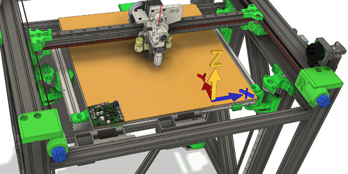
Accelerometer boards usually have an XYZ arrow to aid orientation. The Z axis is generally in the direction of the top face of the board/chip. The default alignment is to align the axes on the board with the axes of your machine.
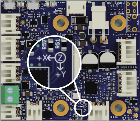
You can add parameter I (uppercase 'i') to the M955 command if you need to change the default orientation.
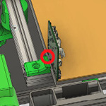
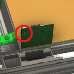
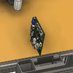
The I (orientation) parameter tells the firmware which of the 24 possible orientations the accelerometer chip is in relative to the printer axes. It is expressed as a 2-digit number. The first digit specifies which machine direction the Z axis of the accelerometer chip (usually the top face of the chip) faces, as follows: 0 = +X, 1 = +Y, 2 = +Z, 4 = -X, 5 = -Y, 6 = -Z. The second digit expresses which direction the X axis of the accelerometer chip faces, using the same code. If the accelerometer chip axes line up with the machine axis, the orientation is 20. This is the default orientation if no orientation has been specified.
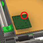
Forum user Nuramori has produced a graphical guide to help illustrate the orientation options with a Duet 3 ToolBoard 1LC. His images use a Toolboard 1LC rev 1.1, however the same orientations apply all toolboards with onboard accelerometer: v1.1,v1.2 and v1.3).
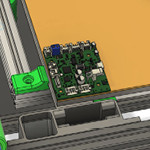
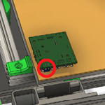
The table below uses his work to show all of the possible orientations of a Duet 3 Toolboard 1LC, with the appropriate M955 command.
Match the image to your Duet 3 Toolboard 1LC orientation, and note the I value associated with the image. The OUT_0 connector on the board, a screw down terminal shown in blue below, is used for indexing, and is highlighted with a red circle if hidden. OUT_0 is normally used for the extruder heater.
| Accelerometer axis to machine axis | ||||||
|---|---|---|---|---|---|---|
| +X to +X | +X to +Y | +X to +Z | +X to -X | +X to -Y | +X to -Z | |
| +Z to +X | NA |  M955 P[##] I01 |
 M955 P[##] I02 |
NA |  M955 P[##] I05 |
 M955 P[##] I06 |
| +Z to +Y | 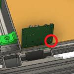 M955 P[##] I10 |
NA | 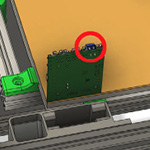 M955 P[##] I12 |
 M955 P[##] I14 |
NA | 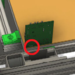 M955 P[##] I16 |
| +Z to +Z | 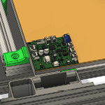 M955 P[##] I20 |
 M955 P[##] I21 |
NA | 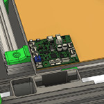 M955 P[##] I24 |
 M955 P[##] I25 |
NA |
| +Z to -X | NA | 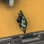 M955 P[##] I41 |
 M955 P[##] I42 |
NA | 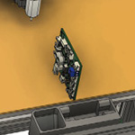 M955 P[##] I45 |
 M955 P[##] I46 |
| +Z to -Y | 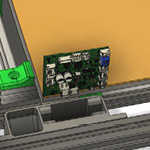 M955 P[##] I50 |
NA | 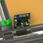 M955 P[##] I52 |
 M955 P[##] I54 |
NA | 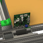 M955 P[##] I56 |
| +Z to -Z | 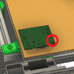 M955 P[##] I60 |
 M955 P[##] I61 |
NA | 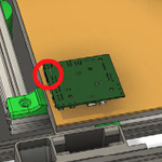 M955 P[##] I64 |
 M955 P[##] I65 |
NA |
¶ Sampling rate and resolution
For most purposes the default sampling rate and resolution should suffice. The default is 1344Hz for the LIS3DH, and 1600Hz for the LIS3DSH and LIS2DW12. You can add R and S parameters to M955 if you want to change them. See M955 for details. The sampling rates available that are likely to be useful for identifying resonances are:
LIS3DH: 1344 400 200
LIS3DSH: 1600 800 400
LIS2DW12: 1600 800 400 200
The bandwidth is usually half the data rate, excep that on the LIS2DW12 when the data rate is 1600Hz the bandwidth is 400Hz.
¶ Using accelerometers
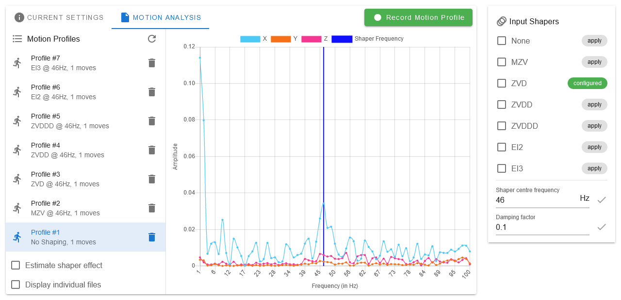
From RRF 3.4, accelerometer data is collected, evaluated and interpreted in the Input Shaping Plugin.
You can run the accelerometer commands manually, and record the results. See the "RRF 3.3 and manual commands" tab for details.
Note the 'Accelerometer' plugin (shipped with RRF 3.3) has been replaced by the 'Input Shaping Plugin'.
Prior to making measurements with the accelerometer, disable any input shaping (including DAA if you are using it), unless of course you are trying to establish the effect of using input shaping.
¶ Collecting data
Use command M956 to collect accelerometer data. RRF 3.3 only supports capture mode A0 (immediate capture), but the A parameter must be present. Here is a typical command to capture data for a travel move in the X direction:
; Duet 3 and 2, accelerometer connected to mainboard (M956 P0)
G1 X-50 G4 S2 M956 P0 S1000 A0 G4 P10 G1 X50 F20000

; Duet 3 Toolboard 1LC at CAN address 121 (M956 P121.0)
G1 X-50 G4 S2 M956 P121.0 S1000 A0 G4 P10 G1 X50 F20000
This commands the X axis to position -50 (G1 X-50) and then waits for two seconds to let any ringing subside (G4 S2). Then it requests the accelerometer at the device-number (M956 P[n]) to collect 1000 samples (S1000) immediately (A0), followed by a pause of 10ms (G4 P10) to let the accelerometer start and provide a baseline. It then commands a travel move to X=+50 at 20000 mm/min (G1 X50 F20000).
Acceleration measurements captured during movement typically show higher frequency components caused by the motors and belts. For this reason, you may get results that are easier to interpret if you collect data immediately after a sharp stop, using a command such as this:
; Duet 3 and 2, accelerometer connected to mainboard (M956 P0)
G1 X-50 G4 S2 G1 X50 F20000 M400 M956 P0 S1000 A0

; Duet 3 Toolboard 1LC at CAN address 121 (M956 P121.0)
G1 X-50 G4 S2 G1 X50 F20000 M400 M956 P121.0 S1000 A0
RRF 3.4beta1 and later allow you to name the file that data is written to using an additional F parameter. The name should end in .csv so that the Accelerometer plugin for Duet Web Control recognises it.
¶ Retrieving the data
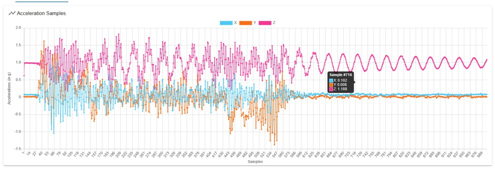
A successful M956 command causes a new file to be created in /sys/accelerometers. The filename includes the CAN address of the board to which the accelerometer is connected, and the date and time that the data was captured. It is in comma-separated-variable format so it can be imported into a spreadsheet. When browsing these files in DWC you may need to click the Refresh button to make DWC aware of newly-created files.
The last line of the file will report the average data rate and the number of overflows recorded. If the number of overflows is nonzero then data samples have been lost and the file should be discarded. Overflows are rare when using CAN-connected sensors, but more common with direct-connect sensors because a single task is used both to collect the data and to write it to file. If you find that you get overflows every time you collect data, try the following:
- Do not use an external SD card while collecting data
- Try a new SD card
- Try a faster SD card
- Reduce the number of samples requested, or the number of axes sampled
- Use a lower sampling rate
¶ Analysing the data
Duet Web Control 3.3 includes an Accelerometer plugin that can be used to display the accelerometer data and its Fourier transform. To enable it, first go to Settings/General/Built-in Plugins and start it. Then go to Settings/Machine Specific/Accelerometer.