¶ Introduction
The Duet 3 Scanning Z probe is a CAN-FD connected inductive sensing board, with compatible inductive PCB coils. It allows for a point mesh of the bed to be built up quickly as no movement in Z is required to read the bed distance, and individual readings happen very quickly. An accelerometer has been added to the PCB as well to allow for the SZP board to also be used for input shaping calibration.
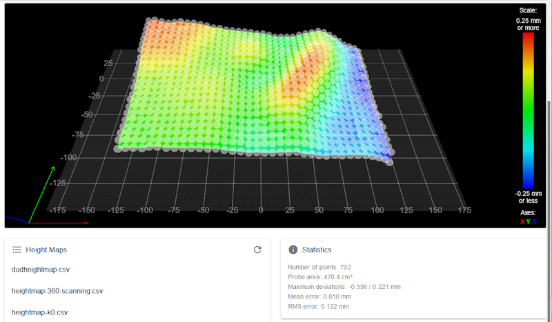
Example mesh of 792 points that took ~20seconds to produce.
¶ Features
¶ Hardware specification
| Processor | ATSAMC21G18A |
| Processor features | 32-bit, 48MHz ARM Cortex M0+, 256KB Flash, 32KB RAM |
| Networking/Comms | CAN-FD interconnect to Duet 3 Tool Distribution Board or Duet 3 Mainboard; serial port |
| Scanning IC | LDC1612 |
| Accelerometer | LIS2DW12 |
| Power monitoring | VIN voltage reporting |
¶ Operating limits
| Input power voltage | 5V |
| Power consumption | <200mA |
| Maximum ambient temperature | 75°C |
| Absolute maximum board temperature | 85°C |
Note: The coil PCB can likely cope with higher temperatures than those quoted above, having no active components.
Duet-supplied FFC cables are rated at 80°C, but cables are available with a higher temperature rating.
¶ Firmware notes
- Compatible RepRapFirmware versions: RRF 3.5 or later
¶ Open source
- The Duet3 SZP is Open Hardware, see our license here.
- All hardware source files are available on Github.
- Both the Duet Web Control web interface and RepRapFirmware are Open Source Software with source files available and actively maintained, see Contributing to development for more information.
- The Duet hardware and RepRapFirmware are built with Open tools: designed in KiCad and Eclipse using open tools means the barrier to getting involved is as low as possible.
¶ Physical properties
¶ Dimensions
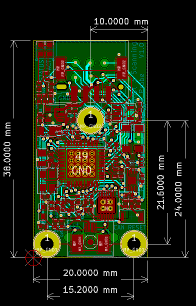
There are three M2 mounting holes and overall dimensions are 38mmx20mm
¶ Coil dimensions
¶ Mounting
- The SZP board can be mounted anywhere within reach of the supplied FFC cable (100mm).
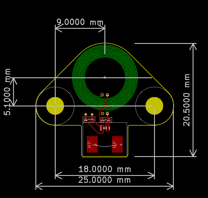
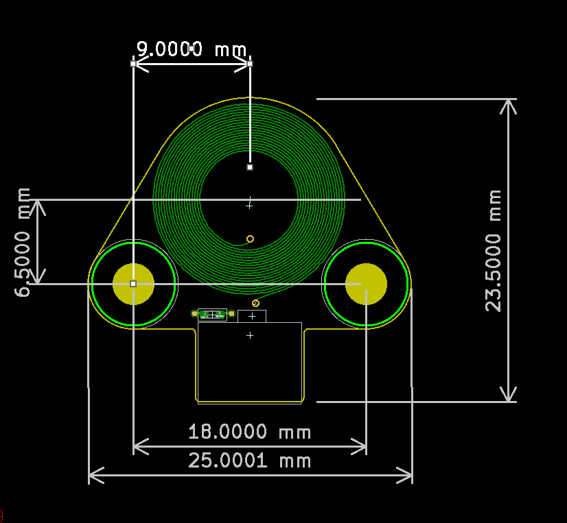
- Duet3D supply two coils, a 12mm coil and a 15mm coil. In theory the 12mm coils are higher resolution than the 15mm coils but we need more testing to confirm which is best, so we provide both.
- Make sure there is no metal in the 30mm ABOVE the coil, or it will pick this up and give false readings
- The bottom of the SZP coil should be around 3mm above the tip of the nozzle. The G31 Z trigger height can be set to around 2mm, so the coil is 5mm from the bed, to avoid the nozzle contacting the bed while keeping the coil close enough to the bed to get an accurate reading.
- Route the SZP ribbon cable away from the coil, ie make sure it doesn't go over the coil
- Ensure that the ribbon cable is FULLY inserted into the tiny connector, at both ends. Try reseating this if you continue to get erratic readings
- You can use M2.5 countersunk screws (often supplied with smaller fans) to mount the coil, which stick out about 0.7mm. M3 countersunk screws stick out a bit further. There are M3 screws with low profile heads, usually between 0.8mm and 1mm; search for "m3 ultra low profile thin head".
Here is an example with it mounted on a Mini Stealth Burner tool on a Voron:
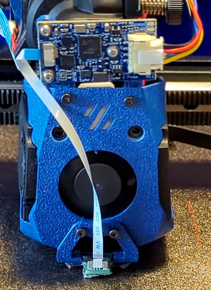
Note: this board is a v0.1 development board; CAN_L and CAN_H are swapped on the silkscreen.
¶ 3D Model
The STEP file for the SZP board is available here: https://github.com/Duet3D/Duet3-ScanningZProbe/tree/master/v1.0
STEP files of both coils are available on Github here.
¶ Physical connections
¶ Wiring diagram
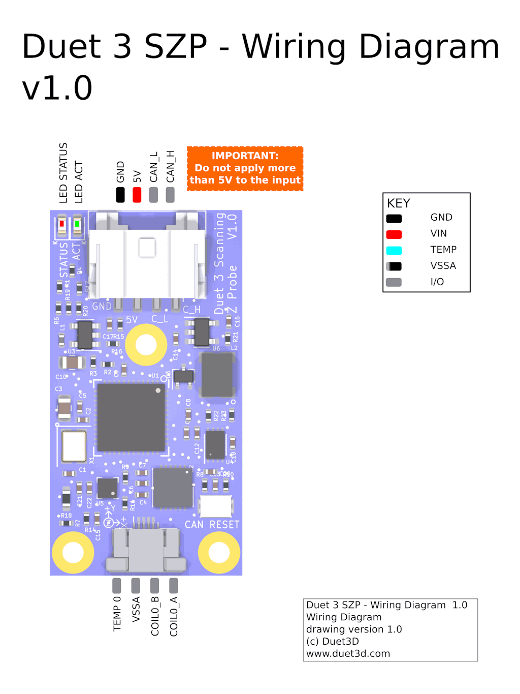
¶ Description of Connections
Duet 3 Scanning Z probe has the following connectors:
| Connector | Label | Function |
|---|---|---|
| 4-pin JST PA | GND, 5V, CAN_L, CAN_H | +5V power and CAN |
| 4-pin 0.5mm pitch FFC | Temp, VSSA, COILA, COILB | Connection for FFC cable to coil |
¶ LED indications
LEDs are provided to indicate the following:
| Label | Colour | Function |
|---|---|---|
| ACT | Green | Indicates activity on the CAN-FD bus |
| STATUS | Red | Status LED. See description below |
Status LED: In normal use, the red LED flashes slowly in sync with the main board to indicate that it has CAN sync, or flashes continuously and rapidly to indicate that it doesn't. It also flashes startup error codes, for example if the bootloader doesn't find valid firmware on the board. For a list of these error codes see CAN connection basics.
¶ Power wiring
Supply 5V to the GND and 5V pins of the 4-pin JST PA power/CAN connector on the board, observing the correct polarity. Connect 5V and GND pins to a source of 5V (e.g. an IO port on the Duet 3 mainboard, expansion board or toolboard).
If you use a relay to control VIN power to the board, ie the power supply is already switched on, and a relay is used to turn on power to the board, you should use an inrush current limiter wired in series with VIN. See the section on Inrush current here.
OUT ports on the mainboard should NOT be used to switch power to expansion or tool boards directly. See the note at the end of the 'inrush current' section at the link above.
¶ CAN
Connect CAN-FD wires to CAN_H and CAN_L pins of the 4-pin CAN and power connector. Connect the CAN_H and CAN_L pins to the CAN-FD bus.
¶ Directly connected to main board
 If just using an SZP and a mainboard with no tool boards or other Duet 3 expansion boards, CAN can be connected directly to:
- the two-pin KK CAN connector on the Duet 3 Mini 5+
- the RJ11 CAN1 port (not CAN0) on Duet 3 Mainboard 6HC and 6XD
Note: The CAN bus needs terminating at the last device, so terminate the bus at the SZP. See 'Terminating resistor' section below.
¶ Connected to expansion or tool board
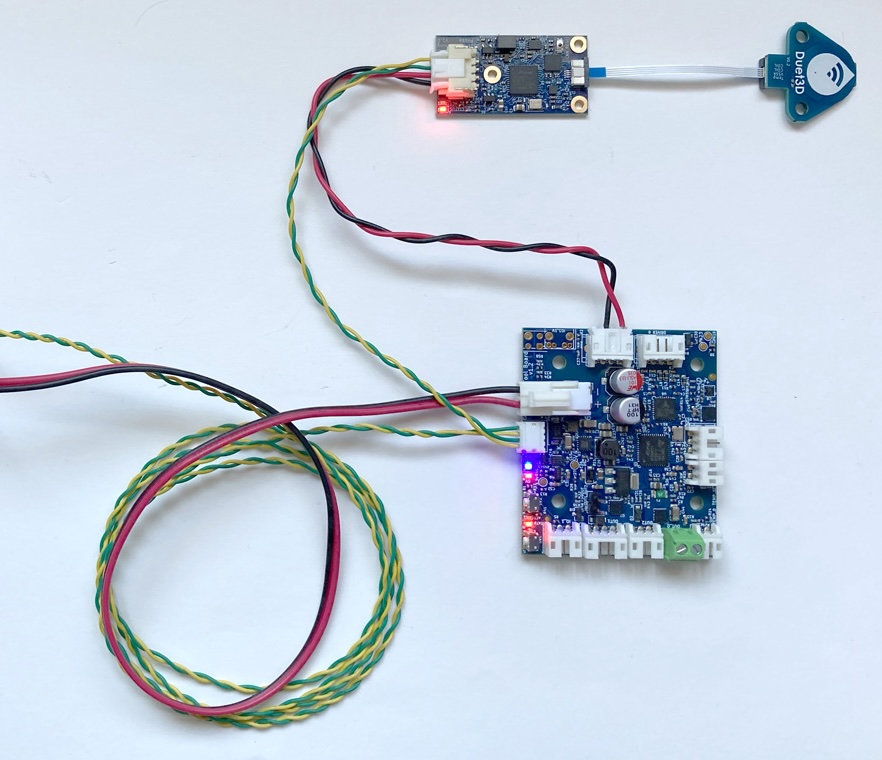 If adding the SZP to an existing Duet 3 toolboard 1LC, connect the CAN wires to one pair of wires from 1LC, and power the SZP from an IO port.
Note: The CAN bus needs terminating at the last device. If this was the 1LC, remove the termination there and terminate the bus at the SZP.
¶ Connected to a Tool Distribution board
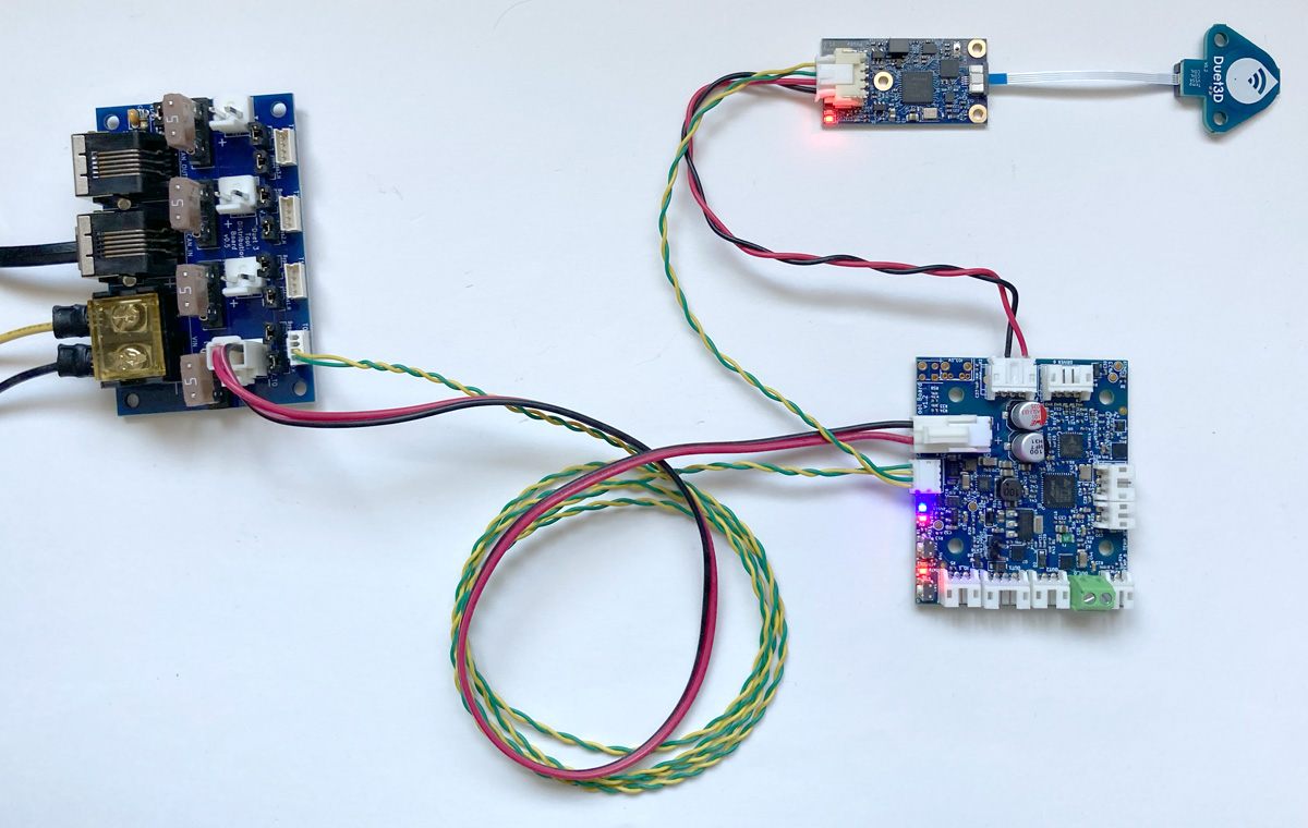 This image shows an SZP connected to a 1LC connected, which is in turn connected to a Duet 3 Tool Distribution Board. The 1LC and SZP are wired as a 'stub'. See the Duet 3 Tool Distribution Board CAN wiring section for more details on this setup.
For further information on CAN connectivity, see CAN connection basics
¶ Terminating resistor
There is a solderable jumper on the back of the SZP to set the termination resistor, if it is to be the last board on the CAN-FD bus.

¶ Commissioning
¶ Startup Time
Add the following to your sys/config.g file
It is recommended to add the following to config.g, before any commands that reference any CAN bus connected expansion boards, eg close to the start of config.g
G4 S2 ; wait for expansion boards to start
¶ Set the CAN address
The default CAN address is 120. Changing the CAN address is only necessary if you have another CAN-connected board with the same CAN address, eg another SZP or toolboard.
All boards in the system must have different CAN addresses. SZPs are shipped set to a default CAN address of 120. If you have more than one SZP on a bus, only one of them must be powered up and connected to the CAN bus initially until a new address is set.
- Send command
M115 B#to verify that the main board can communicate with the SZP, where # is the original CAN address (normally 120) - Send command
M952 B# A##where ## is the new address you want to use, e.g.M952 B120 A100. - Power the system down and up again, or send
M999 B120. This will cause the SZP to restart with the new address. - Send command
M122 B100(or whatever address you chose) to verify that you can communicate with the SZP at its new address - You can now power up the next SZP and commission it in the same way if you have more than one in the system
¶ Testing communication
Check that you can communicate with the SZP by sending
M115 B120
Result should be something like
Duet SZP firmware version 3.5.2 (2024-06-10 13:24:08)
For a full report, send
M122 B120
The status of the accelerometer and Inductive sensor are listed at the end of the report.
¶ Factory Reset
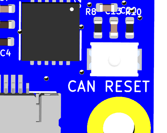
The board will do a factory reset if you power it up with the CAN RESET button held down. The CAN address will be reset to the default (120), the CAN bus timing will also be reset to default (1Mbps), and the bootloader will request a firmware update.
¶ Updating the firmware
Make sure that the SZP is running the same firmware version as the mainboard.
Usually, if you update the firmware using the .zip package of the latest release, connected CAN boards will be updated to the same release.
To check versions are the same:
- Send
M115andM115 B#(where # is the SZP CAN address) to report the firmware version of the mainboard and the SZP. - If they are not the same version, download the matching version firmware files from the RepRapFirmware Github repository.
- The firmware filename is Duet3Firmware_SZP.bin and this needs to be uploaded through Duet Web Control, which will place it in the /firmware folder of the SD card on the attached SBC, or the SD card in the Duet 3 main board if it is running in standalone mode.
- After uploading the file, Duet Web Control should prompt you to install it. To force to update manually use the
M997 B#command, where # is the CAN address of the new board.
Factory resetting the board using the CAN reset jumper will also cause the bootloader to request the firmware file from the mainboard.
¶ Update the bootloader
Updating the bootloader is rarely necessary.
Duet 3 expansion boards and tool boards have a bootstrap loader written to the start of flash so that they can load firmware from the main board via CAN. This bootloader may occasionally need to be updated in order to support new features. See Updating the bootloader on Duet 3 expansion and tool boards.
¶ Connecting peripherals
¶ Scanning Z Probe
¶ Configuration
To use the scanning Z probe as a secondary Z probe, assuming you already have a primary Z probe used for Z homing, add the following to your config.g:
; Scanning Z probe
M558 K1 P11 C"120.i2c.ldc1612" F36000 T36000
M308 A"SZP coil" S10 Y"thermistor" P"120.temp0" ; thermistor on coil
- The K1 parameter configures it as Z probe 1 so as to leave your primary probe as Z probe 0
- If you change the CAN address, the CAN address in M558 C parameter and M308 P parameter will need to change.
¶ Calibration and usage
For SZP calibration and usage, see Scanning Z Probe calibration
¶ Accelerometer
Add the following to your config.g:
M955 P120.0 I20 ; Add accelerometer on SZP with CAN address 120 and specify orientation
See M955 for how to setup and configure the accelerometer.
¶ Orientation
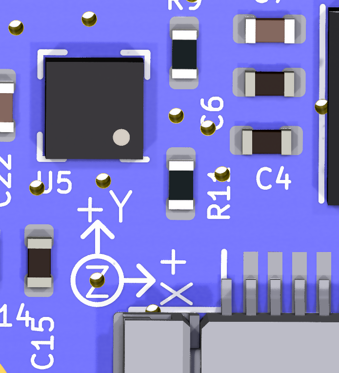
NOTE: there is an errata in the silkscreen orientation arrows on the SZP v1.0 PCB. The correct orientation is:
The +X axis is in the direction of the +Y arrow
The -Y axis is in the direction of the +X axis
The +Z axis is in the direction of the top face of the board/chip.
See this thread on the forum for more details. This will be amended on future versions of the board.
The Duet 3 Scanning Z Probe has an XYZ arrow to aid orientation of the accelerometer, see image below. The Z axis is in the direction of the top face of the board/chip. The default alignment is to align the axes on the board with the axes of your machine (equivalent to I20 in the M955 command), but as that alignment may not be convenient it is configurable in M955.
¶ Calibration and usage
For an overview of using accelerometers to capture data on axis movement see: Connecting an accelerometer
¶ PCB Revision History
- Changed to LIS2DW12 accelerometer
- Added coil connecter test pads for ATE
- Changed to a 4 pin FFC from 6 pin on v0.1
- Silkscreen improvements
initial prototype, internal testing only
