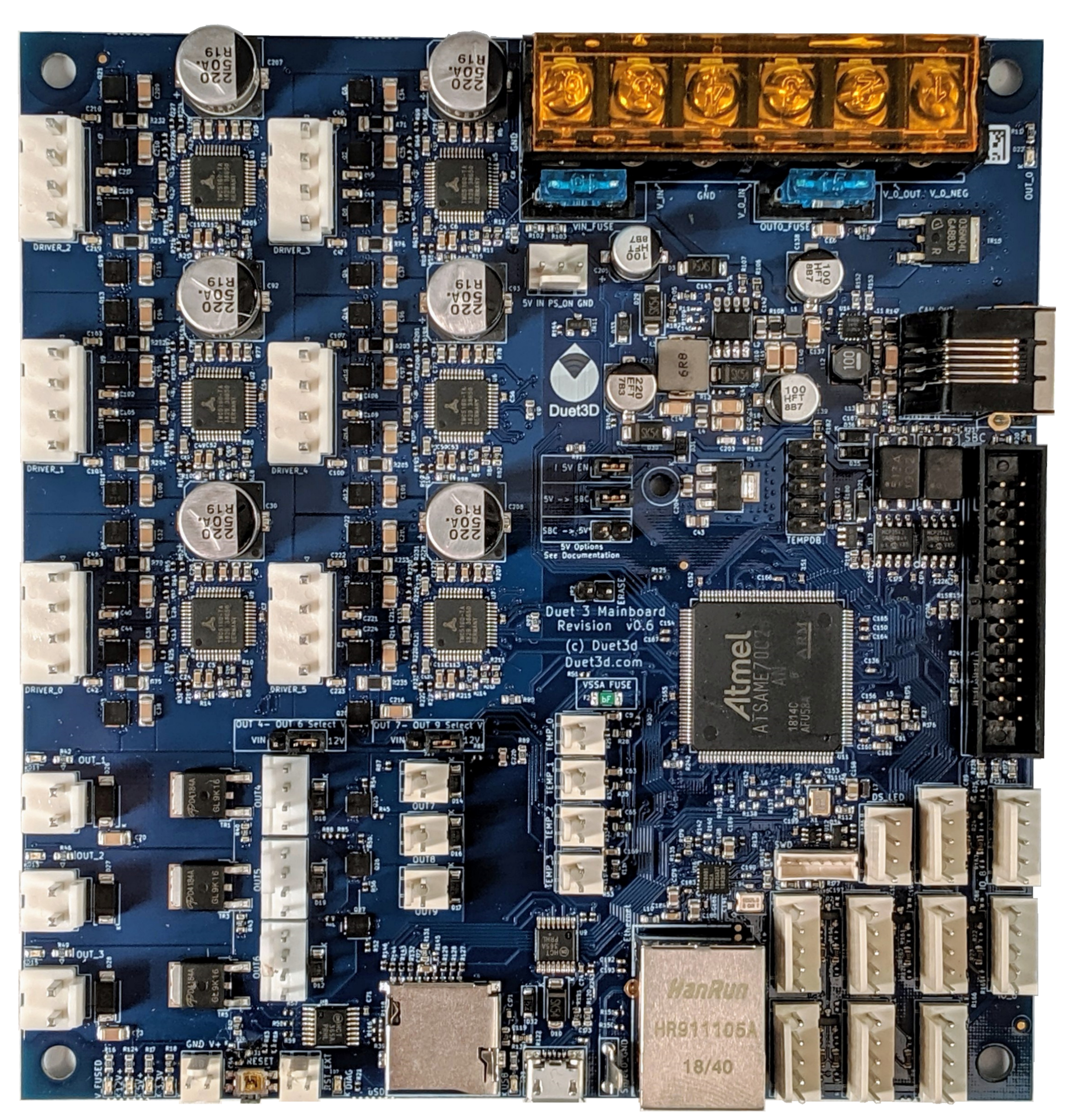
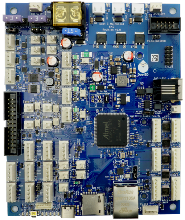
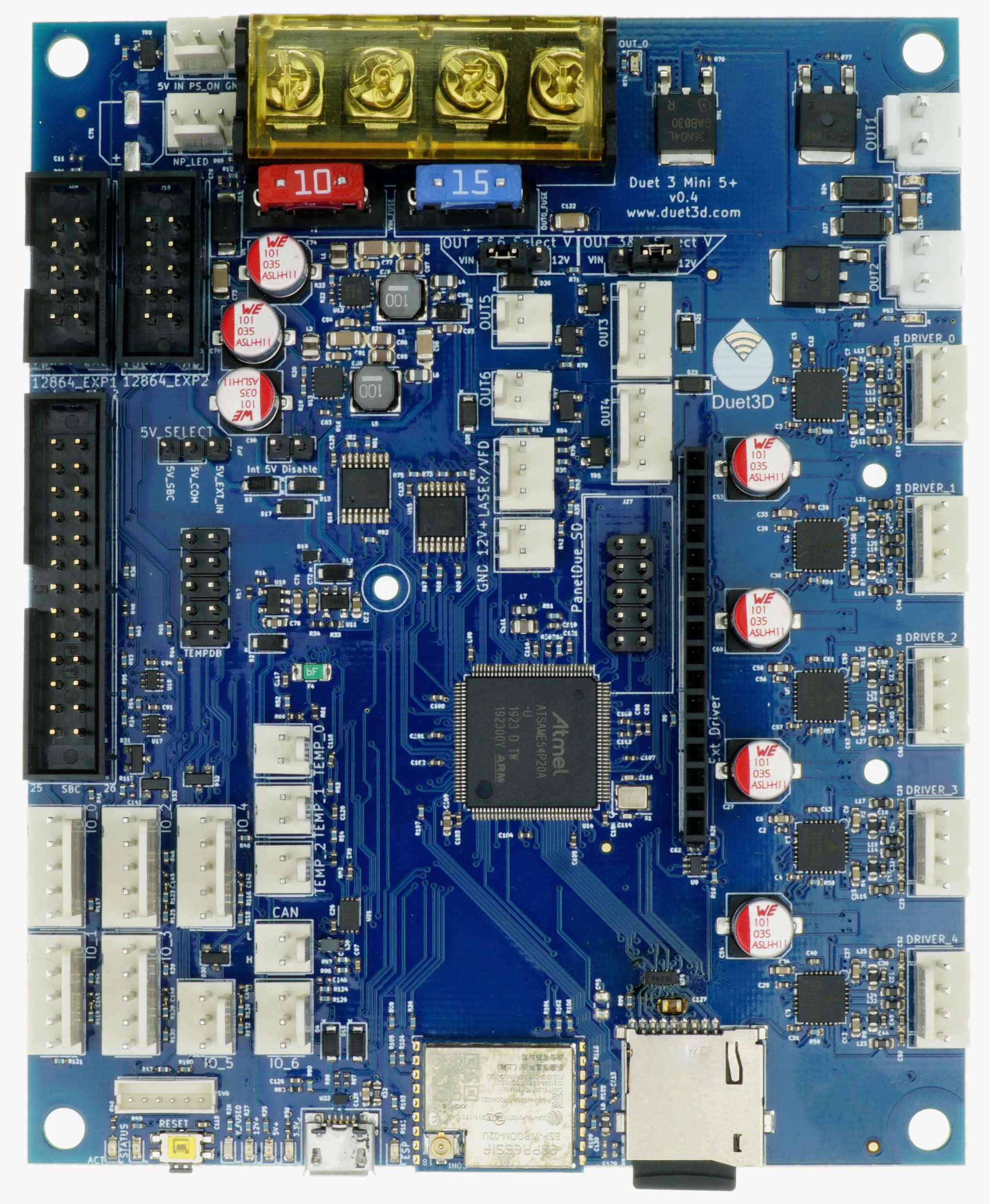
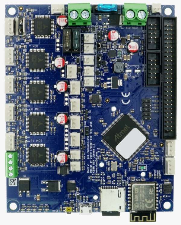
¶ The Duet family of motion controllers
¶ Current production Duet mainboards
| Feature | Duet 3 Mainboard 6HC | Duet 3 Mainboard 6XD | Duet 3 Mini 5+ WiFi | Duet 3 Mini 5+ Ethernet | Duet 2 WiFi | Duet 2 Ethernet |
|---|---|---|---|---|---|---|
| Board image |  |
 |
 |
 |
||
| Processor | ATSAME70Q20B | ATSAMV71Q20B | ATSAME54P20A | ATSAM4E8E | ||
| Processor features | 32-bit, 300MHz ARM Cortex M7, 1Mb flash, 384Kb RAM, hardware floating point (double precision), DMA, 32Kb cache | 32-bit, 120MHz ARM Cortex M4F, 1Mb flash, 256Kb RAM, hardware floating point (single precision), DMA, 4Kb cache | 32-bit, 120MHz ARM Cortex M4F, 512Kb flash, 128Kb RAM, hardware floating point (single precision), DMA, 2Kb cache | |||
| Networking | 100BaseTX Ethernet, or via attached SBC | 2.4GHz WiFi with external antenna, or via attached SBC | 100BaseTX Ethernet, or via attached SBC | 2.4GHz WiFi (internal and external antenna versions available) | 100BaseTX Ethernet | |
| Support for attached Raspberry Pi or other Single Board Computer (SBC) | Yes | Yes | Yes, from RRF 3.2 (requires hardware modification) | |||
| Stepper drivers on-board | 6 x TMC2160 or TMC5160 | NA | 5 x TMC2209 | 5 x TMC2660 | ||
| Stepper driver features | Up to 6.3A peak current, microstep interpolation from any setting to x256, stall detection, stealthChop2 | NA | Up to 2.0A peak current (TBC), microstep interpolation from any setting to x256, stall detection, stealthChop2 | Up to 2.5A peak current, microstep interpolation from x16 to x256, stall detection | ||
| Stepper driver expansion | Almost unlimited expansion using CAN-FD-connected expansion boards | 2 additional TMC2209 stepper drivers; further expansion via CAN-FD | Up to 7 additional stepper drivers, of which up to 5 can be TMC2660 | |||
| External stepper driver support | Via CAN-FD bus | 6 ports with step/direction/enable outputs, and fault inputs. Signalling is 5V single ended. Also via CAN-FD bus | Possibility of driving 2 external stepper drivers from stepper driver expansion connector, or via CAN-FD bus | Up to 7 external stepper drivers when not using DueX expansion board. Signal levels are 3.3V. A 4-channel expansion breakout board is available to level shift them to 5V. | ||
| High current outputs | 1 x 15A, 3 x 6A each | 3 x 6A each | 1 x 15A, 2 x 5A each | 1 x 15A, 2 x 6A each | ||
| Medium current outputs | 6 x PWM-controlled outputs, of which 3 support tacho input. Voltage selectable between VIN / 12V / external power, in 2 banks. 1 x VIN-voltage, always-on output. 1 x 12V, always-on output | 4 x PWM-controlled outputs, of which 2 support tacho input. Voltage selectable between VIN and 12V in 2 banks | 3 controlled fans, 2 always-on fan connectors, voltage selectable between VIN, 5V or external supply (all fans together); 6 more controlled fans on expansion board | |||
| Thermistor/PT1000 inputs | 4, optimised for 100K thermistors and PT1000 sensors | 3, optimised for 100K thermistors and PT1000 sensors | 3, optimised for 100k thermistors, can support PT1000 sensors with reduced accuracy | |||
| PT100 and thermocouple daughter board support | 2 boards (4 channels) | 1 board (2 channels) | 2 boards (4 channels) | |||
| Heater/thermistor expansion | Via CAN-FD expansion boards | Limited expansion via CAN-FD | 5 more extruder heater outputs and thermistor inputs, 2 more PT100/thermocouple daughter boards (4 channels) | |||
| Endstop or filament monitor inputs | 9 on-board I/O connectors for endstop, filament monitor, Z probe, hobby servo or PanelDue connection. Inputs are 30V-tolerant. Almost unlimited expansion via CAN-FD-connected expansion boards. | 9 on-board I/O connectors for endstop, filament monitor, Z probe, hobby servo or PanelDue connection. Inputs are 30V-tolerant. 4 of the 9 pairs of IO also have alternative opto-isolated connectors. | 5 on-board I/O connectors, 2 input-only connectors = 7 in total for endstop, filament monitor, Z probe or PanelDue connection. Inputs are 30V-tolerant. Further expansion via CAN-FD-connected expansion boards. | 5 on-board (STP pins are 8V-tolerant on revision 1.04 and later), 7 more on expansion header. | ||
| Endstop status LEDs | No | Yes | ||||
| Z probe connector | See under Endstop or filament monitor inputs | 4-pin with IN/GND/MOD/3V3 pins (IN pin is 30V-tolerant in revision 1.04 and later) | ||||
| Servo support | See under Endstop and filament monitor inputs. Also one output with 5V signal level for servo, laser or VFD converter (shared control signal with one of the 2-wire fan outputs). | See under Endstop and filament monitor inputs. Also one output with 5V signal level for servo, laser or VFD converter (shared control signal with one of the 2-wire fan outputs). | Up to 5 via expansion connector (3.3V drive unless expansion board used) | |||
| Input power voltage | 11V to 48V* | 11V to 30V | 11V to 25V | 11V to 25V | ||
| Power monitoring | VIN voltage and 12V regulator output voltage | VIN voltage | VIN voltage and input to on-board 5V regulator | |||
| LCD support | Typically provided by HDMI touch screen attached to the SBC. PanelDue also supported. | PanelDue colour touch screen, mini 12864 mono graphics display using ST7567 controller (3.3V signal levels) | PanelDue colour touch screen | |||
| LED strip support | Neopixel (max. 240 RGBW or 320 RGB in RRF 3.4) or DotStar | Neopixel (max. 80 RGBW or 106 RGB in RRF 3.4, external 5V power required) | Neopixel (max. 60 RGBW or 80 RGB in RRF 3.4, external 5V power required) | |||
| Other expansion | Almost unlimited expansion via CAN-FD-connected expansion boards | Via I/O ports and CAN-FD bus | 4 GPIO pins on Duex 2/Duex 5 expansion board, 16 GPIO pins on third-party SX1509B-based I/O expansion board | |||
| SD card interface speed | 25Mbytes/sec | 22.5Mbytes/sec | 20Mbytes/sec | |||
| RepRapFirmware versions available | 3.0 series | 2.0 series, 3.0 series | ||||
| Dimensions | 140x134mm | 140x115mm | 120x100mm | 120x100mm | ||
*Note 6HC boards before v1.02 had a max VIN voltage of 32V
¶ Version Numbering
The following version numbering system is used for all Duet3D products. Note there are some legacy products that do not conform to this system; please enquire if it is unclear.
<Product Name><Major Revision #>.<Minor revision # or ##><bug fix letter>
Examples
| <Product Name> | <Major Revision #>. | <Minor revision ## or #>1 | <bug fix letter>2 |
|---|---|---|---|
| Duet 2 Wifi | 1. | 04 | a |
| Smart Effector | 1. | 6 |
Notes:
1 Minor revision numbers can start from 0 or 00
2 Bug fix letter can be blank.