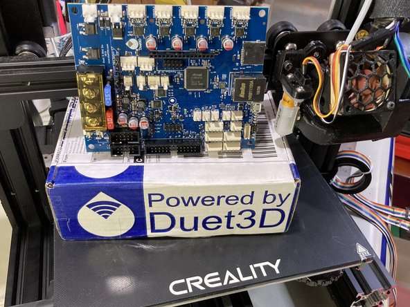
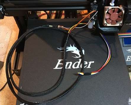
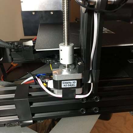
Converting the stock Creality Ender 3 Pro to use the Duet 3 Mini 5+. Part 1 - Mounting and Wiring the board.
¶ Introduction
To learn more about the Mini5+, see here. To learn more about RepRapFirmware3, see here.
The goal of this guide is to provide a guided on ramp to installing a Duet controller board using RepRapFirmware on a basic printer. The details shown will be specific to the Ender 3, but the concepts and techniques used are broadly applicable to all printer types. We will cover basic wiring, initial configuration, commissioning and testing, basic calibration, and finally, adding a RaspberryPi Single Board Computer (SBC), which is an optional feature of the Duet 3 series boards.
The Creality Ender 3 has become a very popular low cost printer option. It's not without its downsides, however. Loud motors, drivers, and fans can be maddening, and the lack of a dynamic web interface and network connection makes interacting with it more painful than it needs to be.
Smaller printers such as these are a good fit for the Duet 3 Mini 5+ electronics board, which brings the power and flexibility of RepRapFirmware into a smaller, lower cost package. It is still a significant upgrade as it provides powerful and quiet Trinamic drivers along with providing future expandability via the CAN-FD bus and SBC connection.
The combination of low cost, but well built printer frame and suitable mechanics with the power and flexibility of the Duet and RepRapFirmware, work together to create a very affordable and capable machine.
¶ Other guides in this series
- Part 1 - Wiring
- Part 2 - Configuration
- Part 3 - Commissioning
- Part 4 - Calibration
- Part 5 - Single Board Computer
¶ Preparation
Plan the upgrade. Once you have your Ender 3 pro up and running, you’ll want to plan out your upgrade path before taking it apart, especially if it's your only printer. At the very least you’ll need an adapter to mount the Duet 3 Mini 5+ board in the Ender 3 electronics enclosure. Download link: https://www.thingiverse.com/thing:3612685
You also have the option of replacing the enclosure entirely with something of your choosing. There are a few printable enclosure options on Thingiverse. Though if you go this route, you may need to extend some of the wiring.
Next, go through the LCD menu and record certain details about the firmware settings, mainly axis length, steps per mm, acceleration, max speed, and jerk settings. This will be required when we use the RepRapFirmware Web Configurator to prepare our starting configuration files.
For more details see Adapting an Existing printer to Duet. Most of this information can also be found in the Marlin Configuration.h file. Your SD card from Creality may contain the Marlin files, and it can be downloaded from the Creality website or GitHub repository.
Plan out the wiring connections:
| X motor | Driver_0 |
| Y motor | Driver_1 |
| Z motor | Driver_2 |
| E motor | Driver_3 |
| PanelDue | io_0 |
| Z Probe | io_3 |
| X Endstop | io_5 |
| Y Endstop | io_6 |
| Z Endstop | io_2 |
| Bed heater | Out_0 |
| Hotend heater | Out_1 |
| Bed thermistor | Temp_0 |
| Hotend thermistor | Temp_1 |
| Part cooling fan | Out_3 |
| Hotend fan | Out_4 |
| Case fan | Out_5 |
| LED strip | Out_6 |
It's also useful to have the Duet 3 Mini 5+ wiring diagram to hand.
¶ Optional Upgrades
There are some optional upgrades that are specific to the Ender 3 Pro that are documented here. These include a Z axis lead screw change, BLTouch Z probe, moving the Z axis endstop to the top for a Z max endstop used for power loss recovery, replacing the loud fans with quiet Noctuas, and adding an LED strip for better visibility.
Some of these upgrades will be shown in this guide like the fans, LEDs, BLtouch, and PanelDue, but others like buck converter, lead screw change, will not.
¶ Disassembly & Disconnection
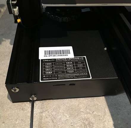
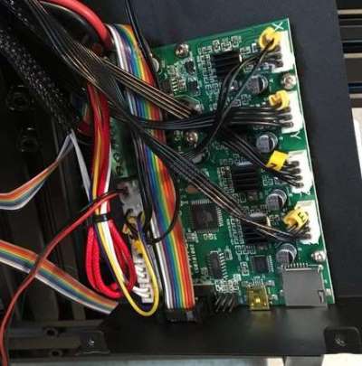
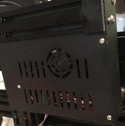 First, we need to take the old Creality board out. Disconnect and remove the display from the frame. Then disconnect the Z end stop wire from the end stop.
Now remove the screws holding the electronics enclosure together. Two on the front, two on top, and 3 underneath.
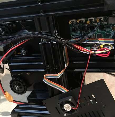 Once the electronics enclosure is loose, you can take the base off and expose the board. Remove the 4 screws holding down the board to the plate. Set all the screws aside where you won’t lose them.
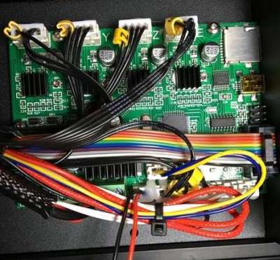 Creality has secured the plugs with a blob of hot glue as strain relief, which is nice, but kind of a pain in our case. Carefully use a small flat blade screwdriver to pry the glue blob off the connector. In my case the glue wasn’t very strong and the connector came loose with a little prying.
Before unplugging the connectors, make sure they are properly labelled and maybe take a picture to help identify where everything goes again for reassembly or if you ever wanted to revert back to the stock setup.
¶ Modifying the Front Panel
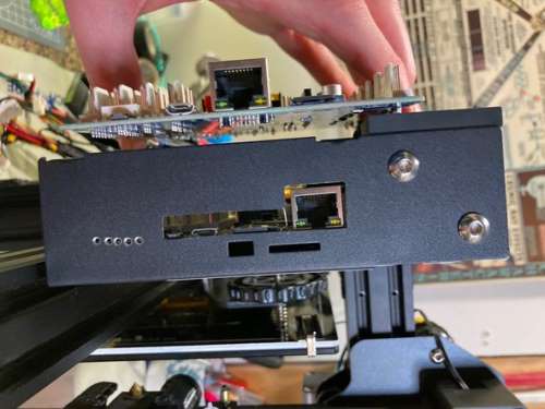 Because the front plate of the enclosure doesn’t have the necessary cutouts for the Mini 5+, we’ll have to make some alterations. First test fit the Mini 5+ board and mark the inside of the front plate for where you need to cut.
At minimum, you’ll need access to the Ethernet port, the SD card slot, and the micro USB connector, and a hole for the reset button.
Optionally you may also want enough space for the ribbon cable between the Mini 5+ and at Raspberry Pi. You may also want to have some holes to see the status LEDs.
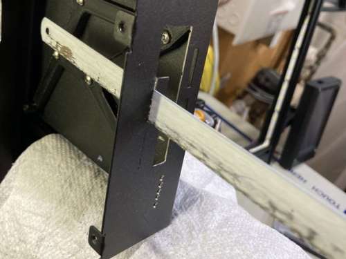 I’ll leave it up to you how you modify the plate. In my case I used a drill and a rotary tool with a reinforced cutting wheel and a hacksaw to make a rough cut, and then used a file to clean up the edges.
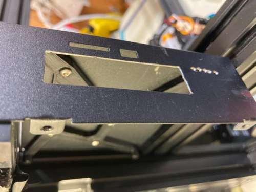 The slot I cut is 70mm long, by 15mm tall, but you could be more selective in how much you cut out.
I unfortunately marred the front panel a bit with the hacksaw. Fortunately, this will be covered up by a Raspberry Pi case later on, so you won't actually see it at all.
¶ Mounting the Mini5+
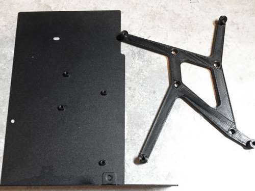 The bolt hole pattern for the stock Creality Ender board and the Duet Mini 5+ is different. An adapter plate is required.
If the Ender is your only printer, be sure to print the adapter before disassembly.
Download link for the adapter bracket: https://www.thingiverse.com/thing:3612685
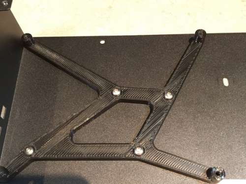 Attach the adapter mount to the plate using the 4 original screws.
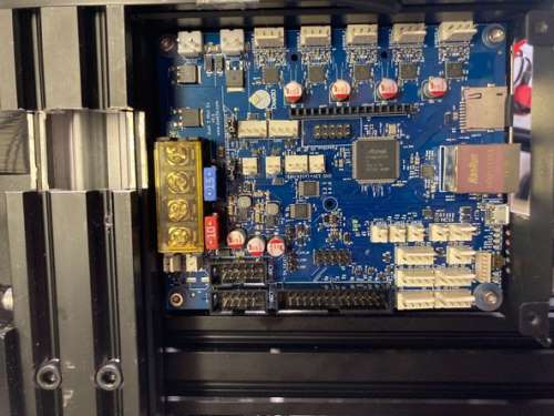 Then attach the Duet 3 Mini 5+ to the mount using 4 6mm M3 screws. Use the clear plastic washers that came with the Mini 5+ in the bag of connectors.
¶ Crimping and Connections
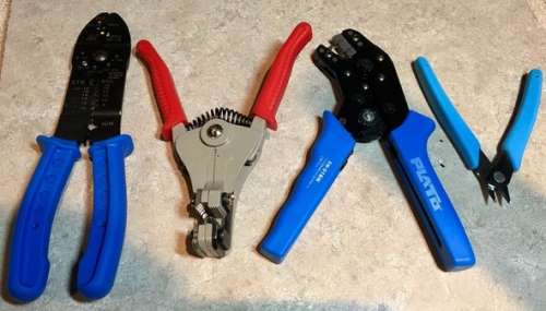
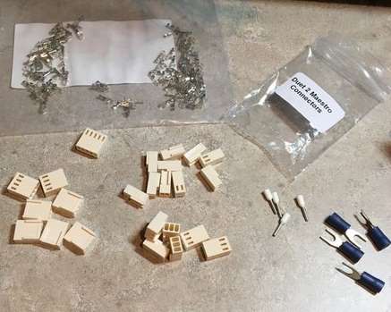 Next, we will re-terminate the wires using the provided crimp connectors. In general snipping off the existing connector, stripping the ends, and re-crimping a new connector that fits the Mini 5+ specifically is the recommended method, and that's what this guide shows. In some cases there are pigtail adaptor cables available to purchase which are also a good choice where available.
The only exception is the motor plugs, which we will modify slightly so they can plug into the Mini 5+ as is. Pay close attention to the orientation of the Creality plugs and the markings on the Creality board in order to preserve polarity of the connectors.
Take out and sort the connector ends that came with the Mini 5+.
You’ll need a crimping tool. There is more information in the Duet Wiring Guide
This video is also helpful: How to Crimp Video
It can also be helpful to use the wiring diagram and the connection table to confirm the pinout and connection:
| X motor | Driver_0 |
| Y motor | Driver_1 |
| Z motor | Driver_2 |
| E motor | Driver_3 |
| PanelDue | io_0 |
| Z Probe | io_3 |
| X Endstop | io_5 |
| Y Endstop | io_6 |
| Z Endstop | io_2 |
| Bed heater | Out_0 |
| Hotend heater | Out_1 |
| Bed thermistor | Temp_0 |
| Hotend thermistor | Temp_1 |
| Part cooling fan | Out_3 |
| Hotend fan | Out_4 |
| Case fan | Out_5 |
| LED strip | Out_6 |
¶ Fan connections
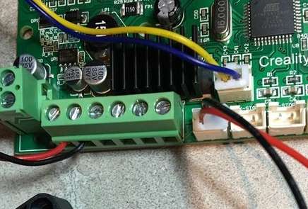 The Ender part cooling fan has the yellow (+) and blue (-) wires, and the hot end heatsink fan has unterminated bare red (+) and black (-) wires, and the case fan has terminated red (+) and black (-) wires.
It can help to label the fan wires and write down the polarity and colour for each fan since the Ender uses various colours.
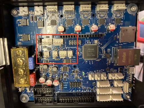
 The Mini 5+ has 4 low current connectors suitable for PWM controlled fans or LEDs. (Plus any number of always-on fans connected directly to VIN) Out3, 4, 5, 6.
- The part cooling fan will connect to OUT 3, connected between the V_OULC1+ pin (+ve) and the OUT_n_NEG pin (-ve), also shown as OUT3- on the wiring diagram.
- The hotend heatsink fan will connect to OUT 4, connected between the V_OULC1+ pin (+ve) and the OUT_n_NEG pin (-ve), also shown as OUT4- on the wiring diagram.
- The case fan will connect to OUT 5, which only has 2 pins for + and -. Ensure you wire them to match for the fan polarity.
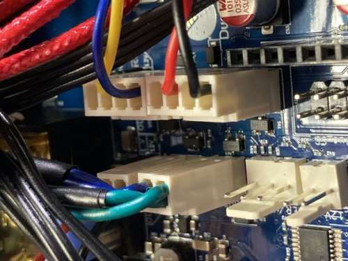
- In addition to the fans, we will be adding a 12v LED strip light. The LED strip will connect to OUT 6, which only has 2 pins for + and -. Ensure you wire them to match for the LED strip polarity.
The voltage for these connectors is determined by a 3-pin jumper block labelled OUT 3&4 Select V. A jumper in the "left" position will power them from the fused VIN supply (max 2A each ). A jumper in the "right" position will power them from the onboard 12V regulator.
If you are using the stock 24v fans, leave the jumper set to the VIN selection. In our case the fans have been replaced with 12v versions, as you'll see in the following steps, so we would select the 12v jumper position.
Note, the draw limit for the internal 12v regulator is 800ma. Make sure that your combination of fans/LEDs etc is below 800ma. Otherwise you must use a buck converter to supply the centre jumper block pin. Check your fan and LED specs to make sure. The limit for 24v VIN is 2A, so you need not worry.
For example, the case fan draws 50ma, hotend fan draws 50ma, part cooling fan draws 50ma, and the LEDs draw 160ma (20ma/segment X 8 segments) for a total draw of 310ma which is well within the limit of 800ma.
Further information on connecting fans can be found in the Connecting and configuring Fans section of the user manual
¶ Noctua Electronics Case Cooling Fan
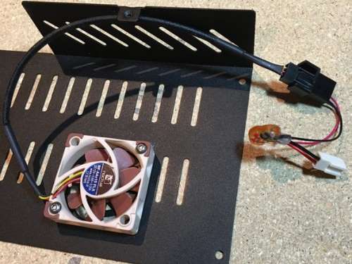 The stock Ender 3 fans are quite loud, so we will replace them with quieter 12v Noctua fans. This is made easy by the onboard 12v regulator on the Mini 5+ removing the need for an external buck converter.
The replacement fan is a Noctua NF-A4x10. This is a 40mm x 40mm x 10mm fan capable of pushing a rated 4.8 CFM at a mere 18db. This same fan will be used for the hotend as well and is the same fan used on the Prusa MK3.
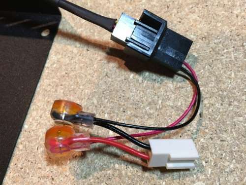 The fan comes with a convenient way of splicing the fan to an existing connector which Noctua calls Omnijoin. This uses 3M Scotchlok terminals that create a physical and electrical butt splice connection between two pieces of wire.
Simply use the included plug on one end, and snip the existing fan wire for the other end. Match black to black in one Scotchlok connector, and red to red in the other. Use pliers to push down the button and lock them in place.
If you are not using Noctua fans and don't have the Scotchlok connectors, you can simply snip the ends and resplice new plugs or use a soldered butt joint to extend the wires of your fans.
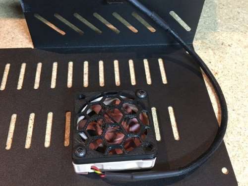 The fan orientation in the first image has the fan blowing into the enclosure. Unfortunately, the grates on the enclosure greatly reduce the amount of airflow for the Noctua fans lower speed. Therefore the fan was flipped to draw air out of the enclosure. In order to keep wires clear of the blades a printed 40mm Fan Guard was added.
Alternatively, you could use a hand file to remove sections of the grates from the case plate to clear the path for the fan blades. Just be sure nothing is likely to enter the blades. Consider adding a less restrictive grate.
¶ 12v LED Lighting
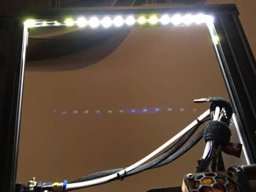 Adding LED strips to the printer is a great way to make it easier to see what is going on with a print. With 4 PWM controlled outputs on the Mini 5+, we can connect a strip of 12v LEDs to shed some light on the print bed and control them with GGode or with a slider in DWC.
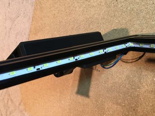 Conveniently, the LED strip is just the right size to fit inside the trench of the V slot extrusion at the top of the frame.The wire can be tucked in along the extrusion as well behind the wheel and down to the electronics enclosure. I used small pieces of electrical tape to keep it in place.
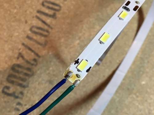
Make sure you note the polarity of the LED strip when you solder the wires and connect them to the right pins of the OUT6 port on the Duet.
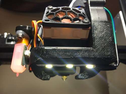 In the next few steps we will be replacing the hotend shroud to add a BLTouch and replace the hotend fan and part cooling fan. Additionally we will add another short piece of LED strip to illuminate the nozzle. Both of these strips will be connected to the same fan terminal, i.e. wired in parallel.
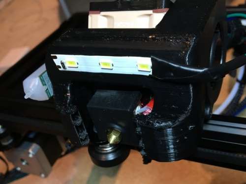 Using the same LED strip that went into the frame, I've cut off a group of 3 LEDs, soldered on a pair of wires, and used super glue to affix it to the bottom of the fan duct of the Hero Me.
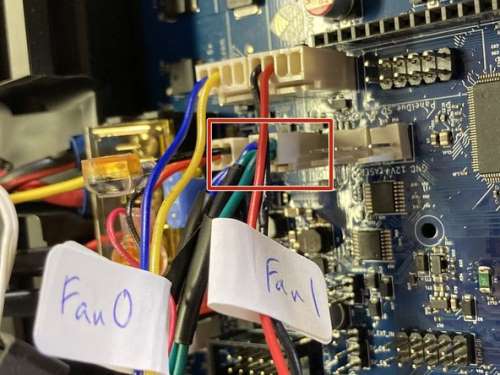 The wires for this LED strip will be wired into the same connector as the LED strip from the frame.
The LEDs are the green and blue wires plugged into the OUT6 port. The photo only shows both LED strips wired in parallel into the same connector.
Alternatively, if you don't care if the LEDs are controllable, you could get 24v LEDs and you can hook them up to VIN and ground so that they turn on when the printer is turned on.
¶ BLTouch Installation
¶ Fan Shroud Swap
In order to use the BLTouch we need a way to mount it. There are some simple brackets available that work with the stock hotend assembly, but we also want to swap the fans and add an LED light strip, and improve the fan duct. Therefore, we'll be using the Hero Me mount which has numerous configuration options.
I've printed the option with the BLTouch adapter, and the single 5015 fan duct. There are other alternatives for replacing the hotend shroud. You can even leave the stock shroud in place and just replace the fans.
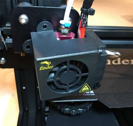 Start the disassembly by removing the 2 retaining bolts for the stock shroud and pulling it away. Be careful not to pull too hard on the hotend heater and thermistor wiring.
We will be replacing the stock heat break fan with the same Noctua NF-A4x10 40mm fan used for the electronics enclosure. We'll be using the same Scotchlok connectors that are included with the Noctua fan.
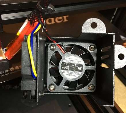
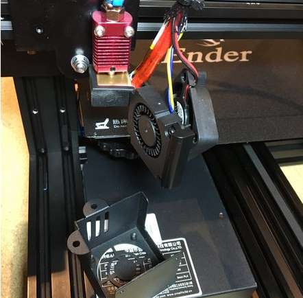
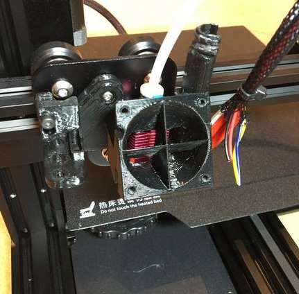 The hotend fan and part cooling blower can then be removed from the shroud. In our case these will be replaced and the wires can be cut as shown in the following step.
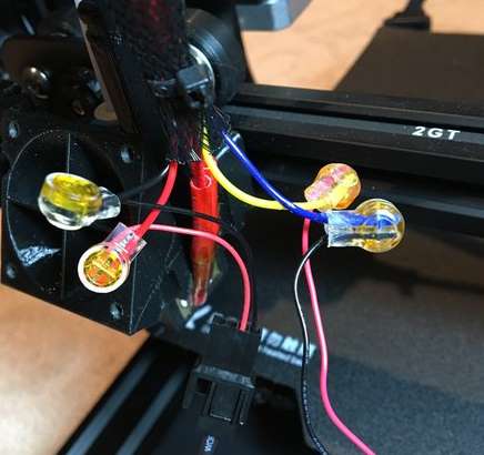 Noctua packages spare Scotchlok connectors in case you make a mistake. But we're also going to use them to swap out the small 4010 blower fan for a larger, more powerful, but quieter 5015 blower fan from Sunon. Model MF50151V2-B00U-A99. The Scotchlok connectors allow us to reuse the existing wiring loom to connect the new fans.
With the Hero Me installed and the fan wires connected we can next attach the noctua fan and the BLTouch to mount.
The same 40mm fan guard used in the electronics enclosure was used for the hotend fan.
As this process involves a swap of cooling shrouds we will describe how to run the PID tuning process for the hotend in the calibration section of the guide.
¶ BLTouch Wiring
You'll need 5 lengths of wire approximately 1 metre in length. You'll need some Dupont connectors and crimps, a crimper, wire stripper, and wire cutter. You'll also need the 5 pin Molex plug connector from the Duet connector package for the Z probe port. The BLTouch end of the wires will have male Dupont pins, and the Duet end will have female Molex.
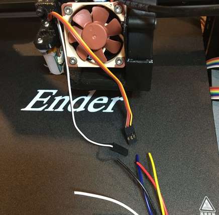
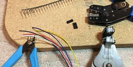
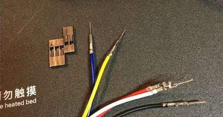
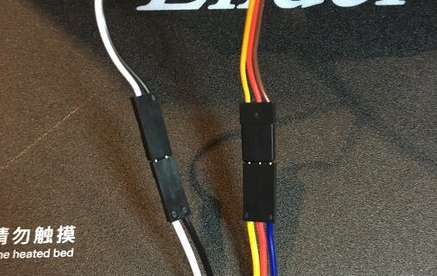 The BLTouch has 5 wires which need to be extended to the Duet board. (Technically 4 if you only extend a single ground.)
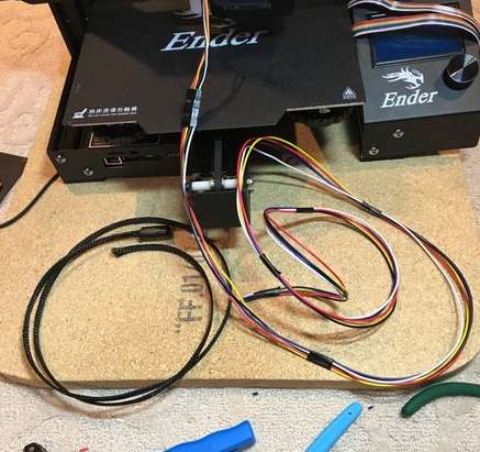 A length of nylon loom can help protect the wires and match the look of the stock hotend wiring loom. In our loom we will include an additional 2 lengths of wire to be used for a small LED strip. These two wires will be piggybacked onto the 2 wires from the LED strip used for the top frame. I've used pieces of electrical tape to bind the wires together into a bundle to make them easier to feed into the nylon wrap.
Adding a wrap of tape or blob of hot glue can help ensure the Dupont connectors stay together. Also ensure they have good strain relief at the hotend.
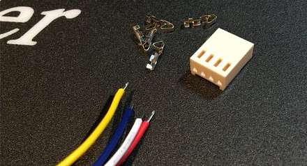
 The Duet Mini 5+ Z Probe port can accommodate all 5 of the BLTouch wires. Note that the 2 ground wires from the BLTouch can be piggybacked to the single Z probe connector in the same way as we did with the LED wiring to the always on fan plug.
It's possible to leave the second BLTouch ground wire disconnected or connect it earlier to the other ground wire so that you only have to route four long wires back to the board.
It's a good idea to test your wires for continuity before completing the installation.
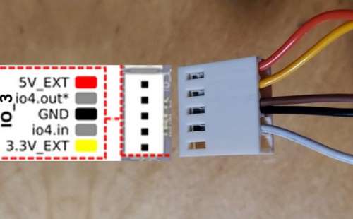
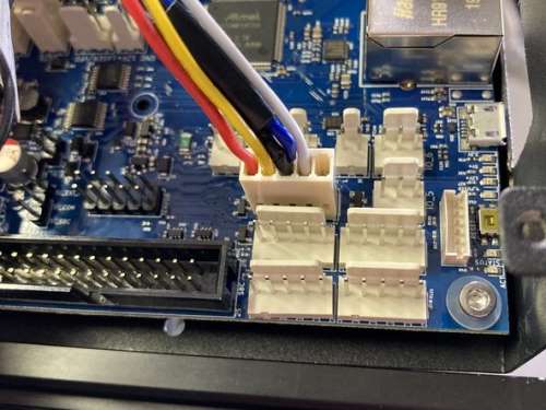 At the Duet end, connect the BLTouch Molex KK plug to the io_3 port. The order of the BLTouch wires at the Duet end requires that the two ground wires are connected to the same pin. This is the black and brown wire in the photo and matches the colour of the BLTouch wiring.I used the same technique as described in the LED wiring for the hotend. A single wire is crimped to the pin, and the second wire is soldered carefully onto the pin io3 to BLTouch connections:
- Red is 5v for power
- Yellow is io3.out for servo control
- Black and Brown are ground wires and have been joined to a single pin
- White goes to io3.in for trigger signal.
- The 3.3v pin is left blank.
This shows the probe plugged into io_4, which isn't PWM capable and won't work. It's just to illustrate the plug orientation.
Note the 2 wires going into the one pin between the yellow and white wires. A piece of electrical tape was used to act as strain relief.
¶ Power Supply and Bed Heater Connections
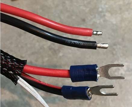 The power supply leads and the bed heater will use the blue spade terminals. You will need a suitable crimper tool for these as well.
The ends of the Ender 3 wires may be tinned, in which case it's best to snip the tinned section off and crimp the base wires.
Note the polarity. Black (-) and red (+). Check for silkscreen markings on the PCB near the connectors and check the wiring diagram.
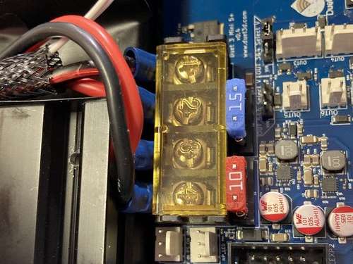 The bed heater will connect to the OUT_0 high current screw terminals. Due to the tight fit with the aluminium extrusion the forks of the spade terminal must be bent 90 degrees.
Be careful with the sharp edges of the cutout portion of the aluminium extrusion. Use a file to take down any sharp corners and add some electrical tape as a barrier. Also ensure proper strain relief to immobilise the wire bundle.
Further information on power supplies and bed heaters is available.
¶ Hot End Heater Connection
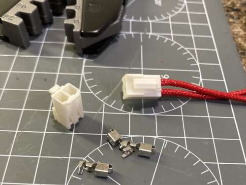 The wires will need to be crimped for the larger 2-pin JST VH connectors.
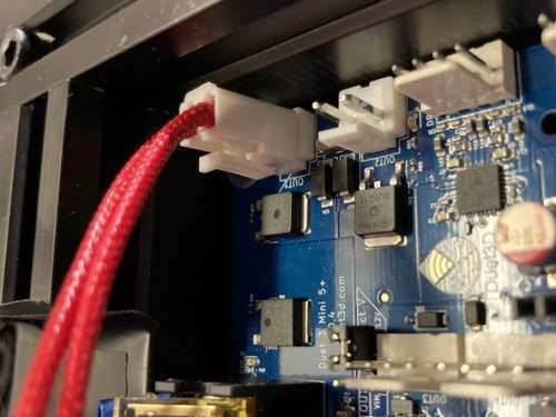 The hotend heater will connect to OUT_1 located in the corner of the board. Heaters do not have a polarity to worry about.
Further information on hot end heaters can be found here
¶ Thermistor Connections
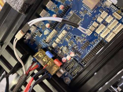 The thermistors do not have a polarity, but you must connect them to the right place:
- The hotend thermistor connects to TEMP_1
- The bed thermistor connects to TEMP_0
The Ender 3 thermistor connections are too short to reach the placement of the TEMP connectors on the Mini 5+ so they will need to be extended.
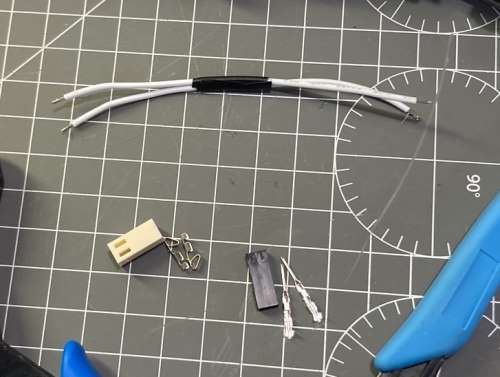
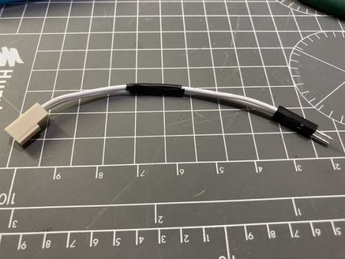 Re-crimping them with the proper locking connector will help ensure they are not easily pulled free. In my case I've used a male Dupont pin to connect the extension and will add a blob of hot glue to hold it in place. Adding a piece of wire with solder is another option.
Further information on thermistors .
¶ Stepper Motor Connections
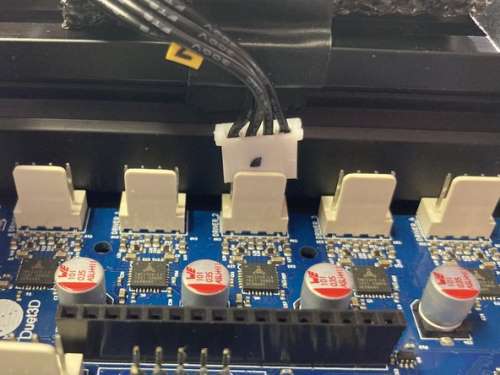 The stepper motor connectors technically do not need to be re-crimped, however the ridges on the motor plugs that ensure they can only be plugged in one way to the Creality board need to be clipped off. A pair of side cutters works well.
This has the advantage of saving a lot of time crimping as well as keeping all the wires in the correct order. However, it does have the disadvantage of no longer being keyed, so you must ensure they are plugged into the board the right way around.
The side of the plug that you snipped the guides off will go towards the white pillar of the board connector. It may help to mark this side of the motor plug with a dot to help you keep track.
If the motor connections are plugged in the wrong way round, no damage to the electronics will occur, but the motors will run backwards. You'll either need to flip the plug or change the motor direction in software.
If you do decide to re-crimp the ends, you must keep the phase pairs side by side, Do not cross the pairs, otherwise you can damage the drivers.
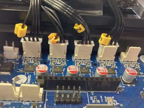 In this case I've used Driver0 for X, Driver1 for Y, Driver2 for Z, Driver3 for E, Driver4 empty. The order isn't critical because the assignments are defined in the config.
There is further information on the connecting motors page.
¶ End Stop Switch Connections
The end stop connectors will need to be redone. The Creality end stop switches have only two wires for signal and ground, but Mini 5+ generalised IO ports with 5 pins, so we will need to be careful that we use the right ones.
If your endstops require a power source, connect the correct wire to either the 3.3v or 5v pins.
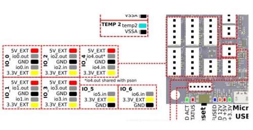 We will use io_5, io_6, and io_2 for the X, Y, and Z Max endstop switches, and io_3 for the BLTouch. io_0 is reserved for a PanelDue which will be shown later.
This endstop arrangement leaves some of the more capable ports open for future use. See here for the io port limitations: Duet 3 Mini 5+ Hardware overview
The main limitations to keep in mind are that a PanelDue 4-wire connection must use io_0, and io_4 is not suitable for BLTouch.
The endstops will be wired to the io.in and ground pins. It doesn't matter which wire goes to which pin for these microswith endstops since all the switch does is complete the circuit. Also note that the position of the io.in and gnd pins differs between the 5 and 3 pin ports.
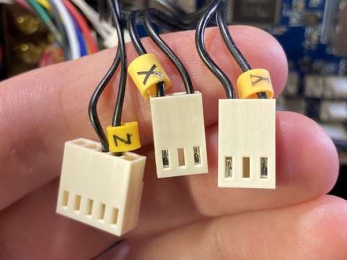 The Z endstop is using a 5 pin connector (io_2) and the X and Y endstops are using the 3 pin connectors (io_5 and io_6).
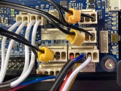 The next step will show the Z endstop being converted to a Z Max endstop for re-homing the Z axis for power loss recovery.
¶ ZMax Endstop
The stock Ender 3 uses a simple endstop switch in the Z min position for homing the Z axis. The mount for the switch is adjustable by sliding it up and down the frame. Unfortunately, the Ender 3 bed will often be cupped and cause a dip in the centre. When levelling the bed at the corners it may prevent the nozzle from touching the bed at the centre.
Removing the Z min endstop mount entirely will allow you to move the nozzle all the way down. Since we're about to install a BLTouch anyway, we may as well remove it.
However, rather than just remove it entirely, we can move it to the top of the frame and use it as a Z max endstop which is useful for resuming after a power loss, since it will be impossible to use the probe to rehome the Z axis while a print object is still on the bed.
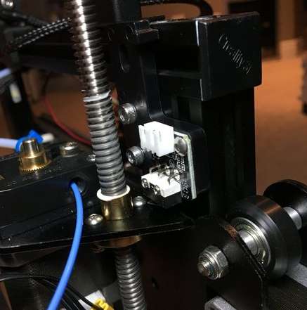
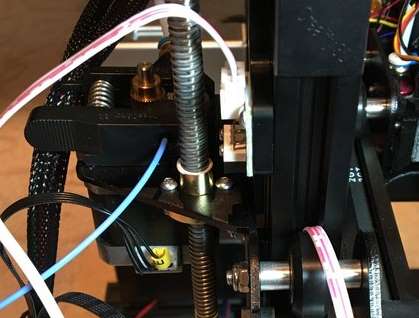 Note the orientation of the endstop mount as installed at the top of the frame. The switch will be triggered when the X axis extruder arm reaches the top. This may limit the amount of Z axis travel, but due to the bowden tube, and wiring harness, this is really the maximum viable travel anyway.
You'll need to extend the endstop wiring. I was able to tuck the wire into the frame extrusion underneath the wheel. I used a small piece of electrical tape to hold it in place. The other end of the wire extender plugs into the stock Z endstop wiring.
In a later guide we will change the config.g and homez.g to reflect the new endstop position.
¶ PanelDue
The 12864 LCD and rotary encoder that comes with the Ender 3 is a functional if basic way of interacting with the printer directly without using the web interface.
However, if you want more control, easier access to macros, access to a gcode console and keyboard, and don't have a computer nearby, the PanelDue makes for an excellent addition to any Duet powered printer.
The case and mount chosen for the PanelDue 5i has an adjustable arm and will require some M4 hardware. It can be found here: https://www.thingiverse.com/thing:2799628
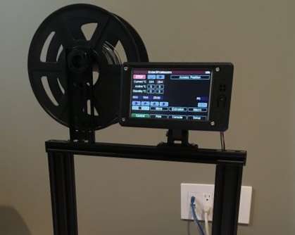 The PanelDue is connected via the 4-wire cable option. This doesn't allow for the PanelDue SD card slot, but it does allow for a much longer and easier to route cabling option compared to the flat 10-wire ribbon cable.
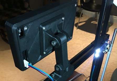 The wires for the PanelDue are routed down the back of the frame extrusion inside the V slot channel and down into the electronics enclosure. A few pieces of electrical tape are enough to keep it in place.
 Following the pinout of the PanelDue, we will connect to io_0 matching 5v, ground, and the transmit and receive pins.
For more information, see the main documentation for the PanelDue.
¶ Reassembly
¶ Onto Frame
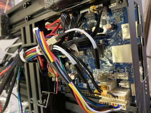 Once you’ve got everything wired up you can reinstall the case onto the frame. Or if you did like me and left the case on the frame and wired everything up in place, now is a good time to route the cables and do some strain relief.
You may find it easier to disconnect some wires temporarily and reconnect them once it’s installed. It’s a tight fit, but it will all fit. I suggest leaving the 2 screws on the front loose and align and tighten the screw directly under the bed first.
For the VIN and bed wires you will need to bend the spade connector upwards to fit back onto the frame.
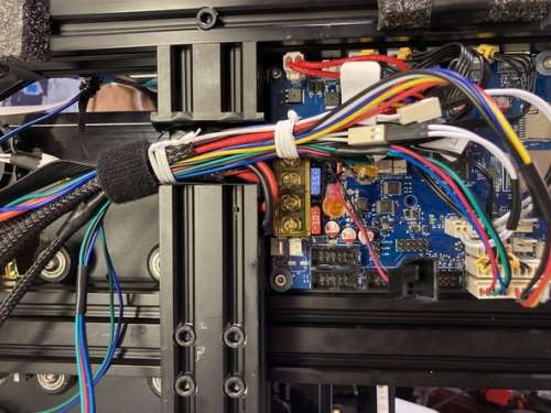 Once you’ve got all your wires reconnected, you can use some zip ties, etc., to provide some strain relief for the bundle leaving the case.
¶ Closing up the Case
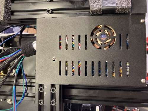 Now reinstall the bottom plate with the case fan attached. It will take a little bit of wiggling to get the tab past the edge of the board. Once all the small screws are secured, you can finally tighten to two large screws on the front.
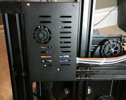 The case fan is installed in the same orientation as it was originally which pulls air out of the case, which should be ideal as it will draw in fresh air through the grills right next to the driver chips. For the currents and loads being used on the stock Ender 3 Pro this should be adequate cooling.
¶ Configuration
This concludes the wiring guide. The next guide will go through using the RepRapFirmware Config Tool to generate a config file set.
