¶ Introduction
This document is relevant to: Duet 2 WiFi/Ethernet and Duet 2 Maestro
Firmware versions: All versions
Difficulty: Moderate
Time Required: 30 minutes - 1 hour
This guide covers connecting hardware, such as power, heaters, motors, endstops, fans, temperature sensors etc., to your Duet 2 mainboard.
Note: The pictures in this guide are from an earlier version of the Duet 2 WiFi/Ethernet however the wiring guide steps are still valid.
If you have any problems with your Duet when using this guide, rather than posting comments, please use our support forum: https://forum.duet3d.com/
¶ 1. Board diagram
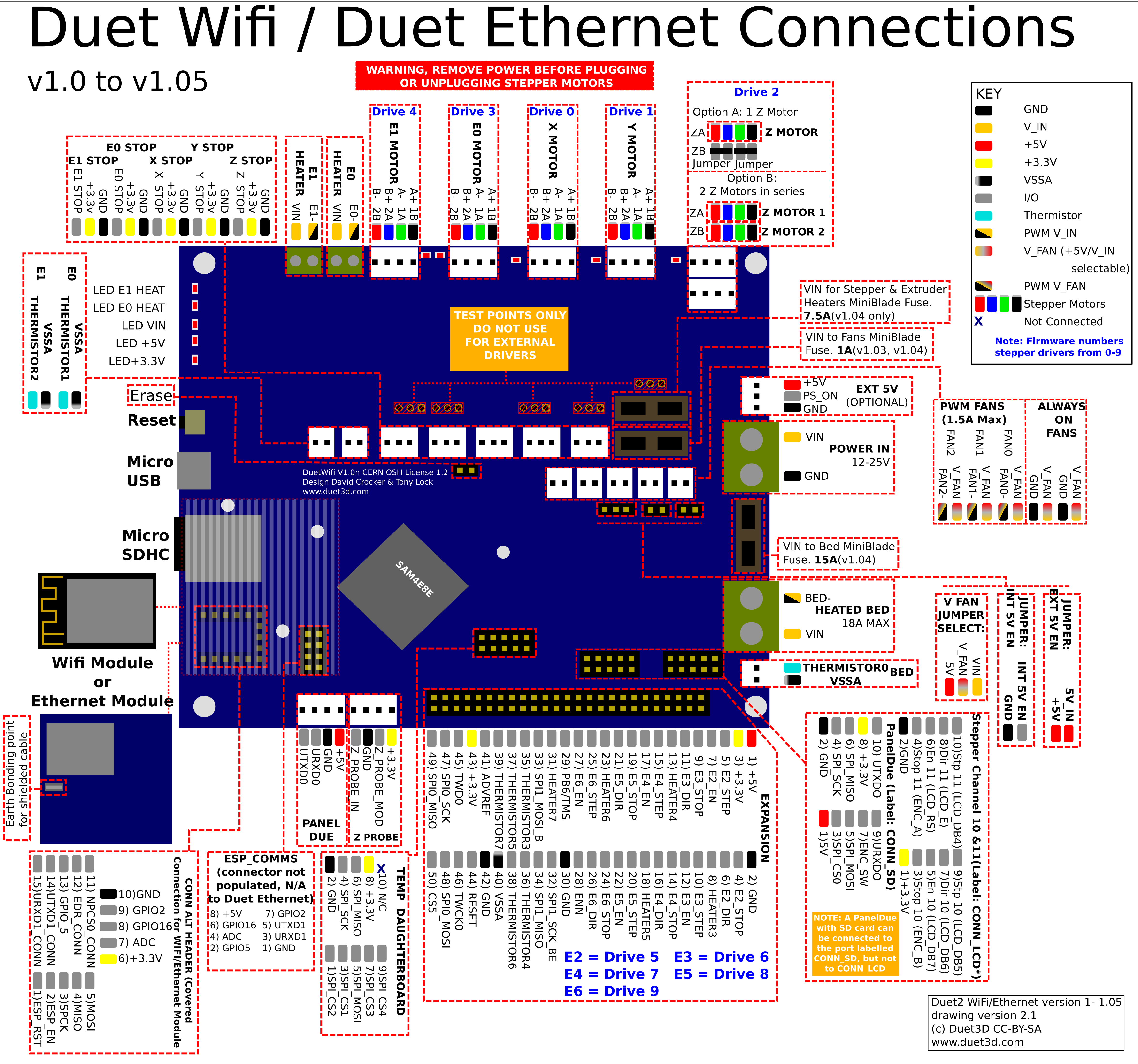
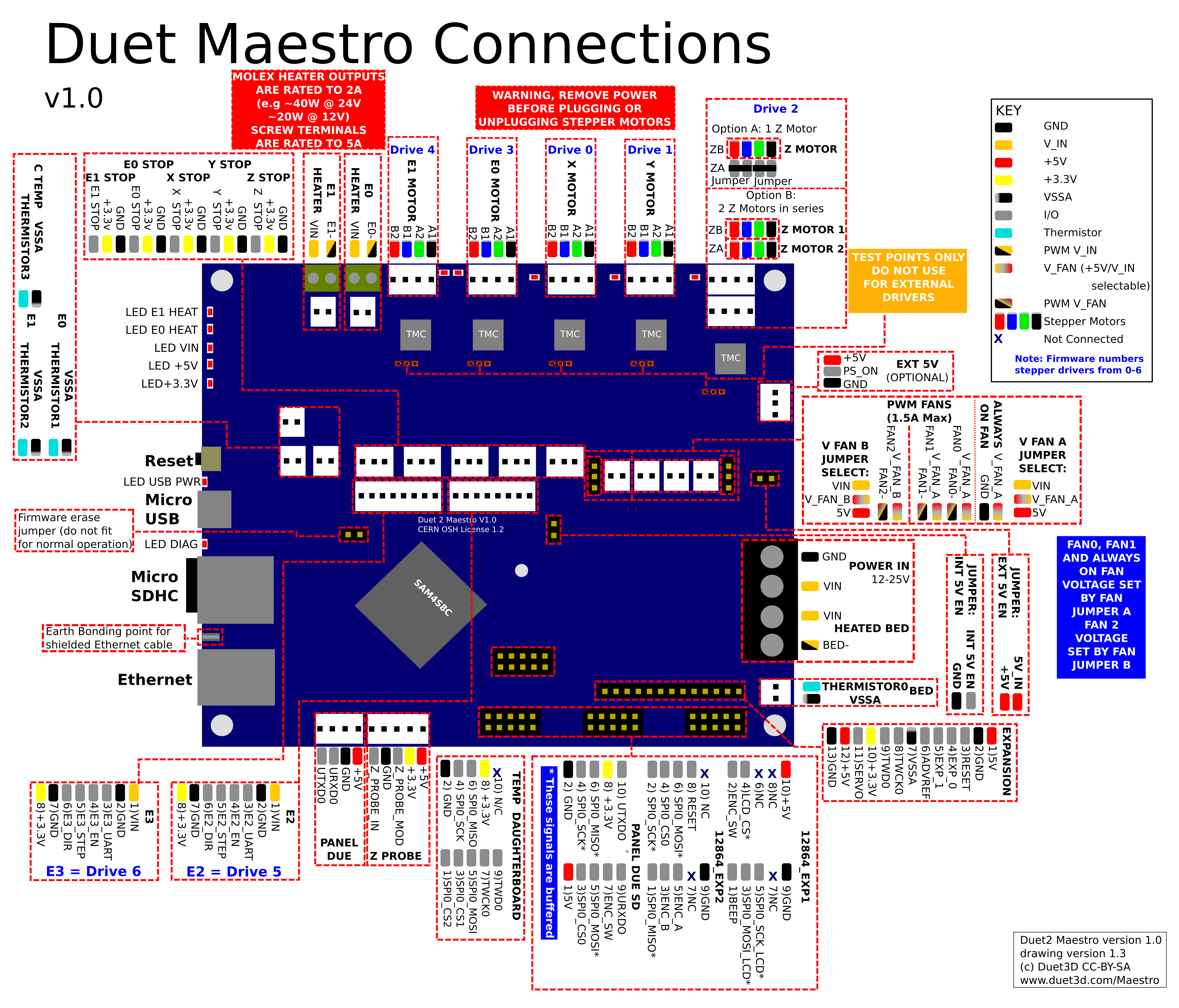
- Take a moment to familiarize yourself with the wiring diagram. It may help to open the high resolution image in another window, or print it out. Click on the images to open them in a new window.
¶ 2. Fire safety
WARNING: it is HIGHLY recommended that you use the provided crimped connectors for the power supply, bed heater and hotend heaters.
- Failure to use these can result in wire creeping, causing the wires to come loose in the screw terminal and possibly create a hot spot or short circuit, which could result in fire.
- Using bare wires may lead to stray wire strands causing short circuits, which could result in fire.
- Do not tin (add solder to) these wires. The solder will flow over time, and will become loose in the screw terminal and possibly create a hot spot or short circuit, which could result in fire.
- The crimp tools shown below are generally available from any hardware store, electrical shop, online etc., and when used correctly will give good quality, solid connections.
- The method of crimp used is called an indent crimp. You should ensure that the tool you use provides a tight crimp of the ferrule to the wire.
- It is also best to use the included Molex connectors for all other connections as they ensure correct polarity and lock into place.
¶ 3. Tools required
To complete the wiring of your Duet, you will usually need:
- Screwdrivers (flat blade and Pozidrive)
- Wire stripper/cutter
- Crimping tool(s) (see tabs below)
- Pliers
¶ Crimping the connectors
Here is a good guide to crimping: Teaching Tech on YouTube

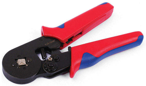 Duet 2 Wifi/Ethernet uses bootlace ferrules on the end of the power supply and heated bed wires, which connect to the screw terminal on the Duet board. Use an appropriate bootlace ferrule crimping tool to crimp the wires in the bootlace ferrule. Tools are available that can crimp the ferrule into a C shape along it's length, or that crimp around the ferrule to make it into a square or hexagonal shape.
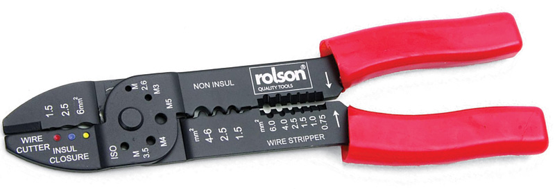
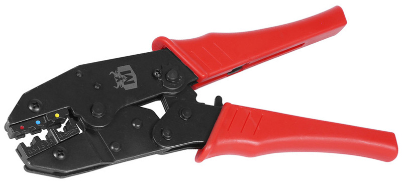 Duet 3 Mainboards and most expansion boards have a 2, 4 or 6-way barrier strip with screw terminals to connect power supply (and heated bed wires if applicable), and are supplied with insulated spade crimp terminals. Use an appropriate crimping tool; we find ratchet wire crimping tools produce better crimps than the non-ratcheting type.

 Duet 2 boards use bootlace ferrules on the end of the medium current (usually hot end heater) wires, which connect to the screw terminal on the Duet board. Use an appropriate bootlace ferrule crimping tool to crimp the wires in the bootlace ferrule, as for the Duet 2 WiFi/Ethernet high current connectors.

 Duet 3 boards use JST VH connectors for heaters. Use a manual tool such as Engineer band.

 Molex KK-compatible connectors are used for all other inputs and outputs on the Duet. Use a manual tool such as Engineer PA-09/PA-20/PA-21 (use the 1.6mm opening for the bare wire, and 1.9mm opening for the insulation), or ratchet crimping tool such as the HT-225D.
¶ 4. Communicating with the Duet board
- You should begin by checking the Duet board and get it connected to your network. Please refer to Getting Connected to Your Duet for details.
- Once you have established communication, unplug the USB lead.
- All wiring should be done with NO POWER to the Duet board!
¶ 5. LED indicators
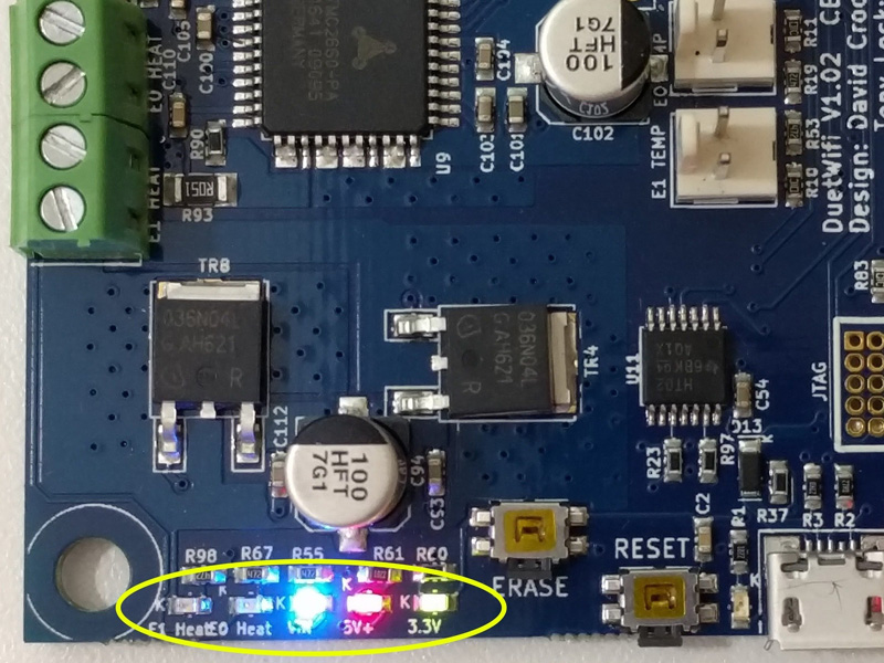
- These indicators show the status of 3.3v power, 5v power, the Vin (power from your power supply) and the two extruder heaters.
- When the board is idle and connected to a power supply, expect the 3.3v, 5v, and Vin LEDs to be illuminated.
- When the board is powered only through an external 5v supply or through USB, expect only the 5v and 3.3v lights to be on.
- In this area you will also find indicators to show when an extruder heater is turned on.
¶ 6. Powering the Duet board
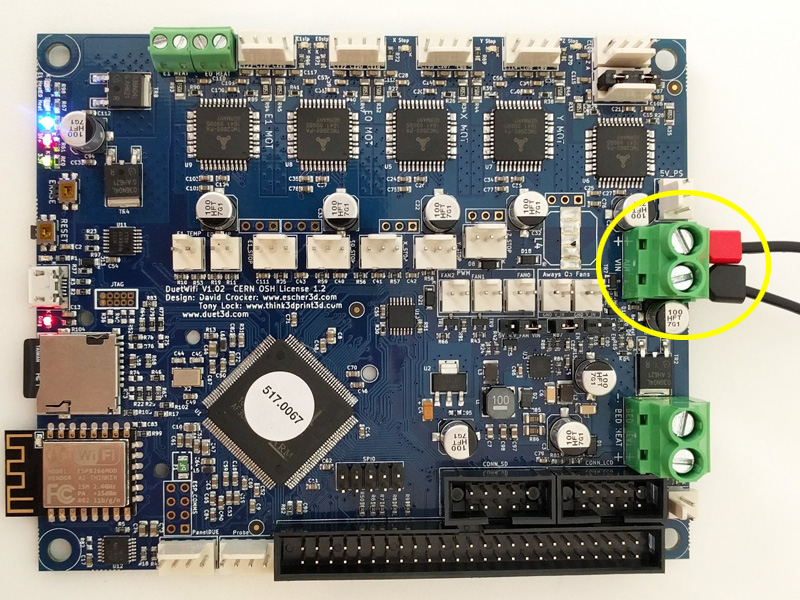
- Connect your power supply wires to the Power In terminal, circled yellow.
- Be sure to observe correct polarity when making the connections. The picture is of a Duet 2 WiFi/Ethernet; check polarity if wiring Duet 2 Maestro or DueX2/5.
- WARNING: It is HIGHLY recommended to use the included ferrules, by crimping them to the wires before putting the wires in the terminal block. Failure to do so could allow the wires to creep over time, become loose, and could possibly short circuit and start a fire.
- Do not tin (add solder to) these wires. The solder will flow over time, and will become loose in the screw terminal.
- Be sure not to twist the terminal block while tightening the screws. It can help to hold the terminal block while tightening.
- Check the screws after a few days/week of operation to ensure they are still snug.
- The gauge of wire should be appropriate to the current that the Duet will draw. This depends on a number of factors, however at its maximum this will be dominated by the 15A for the bed heater. The red and black ferrules provided are 1.0mm^2 and 1.5mm^2 respectively. This relates to 17 and 15 AWG respectively.
- Once connected, make sure USB is disconnected (no power to board). Test the power by turning it on. You should see the LEDs on the edge of the board light up, with the 3.3v, 5v, and Vin LEDs illuminated.
- TURN OFF THE POWER SUPPLY. All wiring should be done with no power to the Duet board.
- For more details, see User manual: Choosing the power supply and User manual: Power wiring
¶ 7. Reset button and firmware erase
¶ Reset button
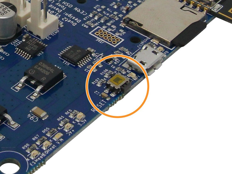 The reset button reboots the board, press if a reboot is needed.
¶ Firmware erase
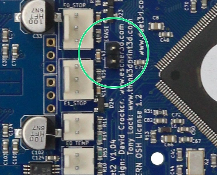
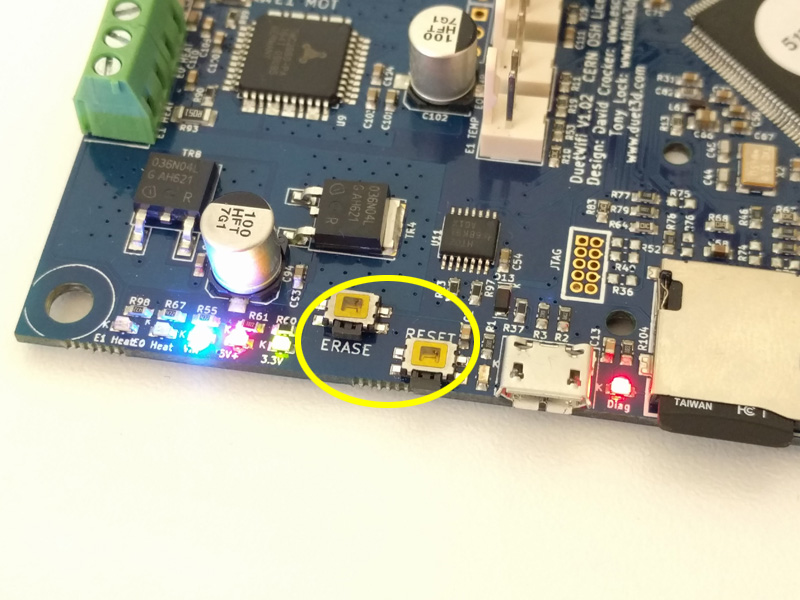 Do not erase the firmware unless you know what you are doing. The firmware does not need to be erased for normal upgrading. The process of reinstalling the firmware after it is erased is detailed here: User manual: Updating firmware. The erase jumper/button will erase the firmware that is stored on the main processor. The SD card does not hold the firmware, just the configuration files.
The firmware is erased in one of two ways depending on the hardware PCB revision:
- For revisions v1.04 and later, and all Duet 2 Maestro boards, it is a jumper which is bridged to erase the firmware (circled green).
- Bridge the 'Erase' pins with a jumper, and apply power, to erase the firmware. Remove the jumper before flashing firmware.
- For all versions prior to v1.04 it is through an erase switch (circled yellow).
- With power applied, press the ERASE switch, then press reset or cycle power.
¶ 8. Hotend Thermistor(s)
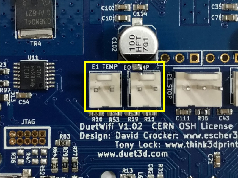
- Connect your hotend thermistors to E0_TEMP and/or E1_TEMP.
- The polarity of thermistors does not matter.
- A thermistor can read up to 290°C. If you wish to print at a higher temperature than this, you should upgrade to a thermocouple or PT100 temperature sensor (see step 18). A PT100 also provides a more consistent reading between multiple sensors and resists noise interference in 4-wire mode.
- Duet 2 Maestro has an additional temperature input, C_TEMP. It is electrically identical to the other temperature inputs, so can be used in the same way.
- For more details, see User manual: Connecting thermistors and PT1000 temperature sensors.
¶ 9. Hotend heaters
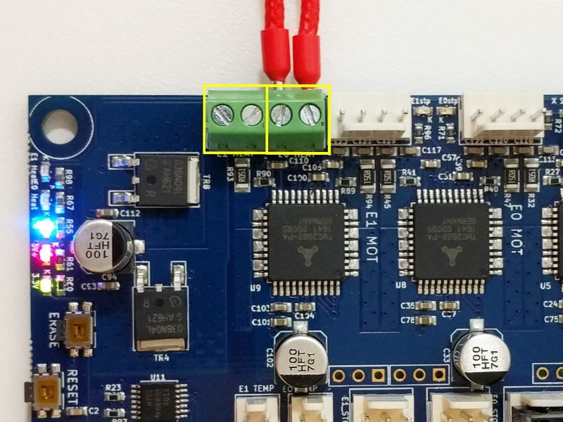
- Your hotend heaters connect to the screw terminals shown in the image, outlined yellow. From left to right, the connectors are E1 and E0.
- Polarity does not matter for hotend heaters.
- WARNING: It is HIGHLY recommended to use the included ferrules, by crimping them to the wires before putting the wires in the terminal block. Failure to do so could allow the wires to creep over time, become loose, and could possibly short circuit and start a fire.
- Do not tin (add solder to) these wires.
- Be sure not to twist the terminal block while tightening the screws. It can help to hold the terminal block while tightening.
- Check the screws after a few days/week of operation to ensure they are still snug.
- For more details, see User manual: Heaters overview
¶ 10. Endstops
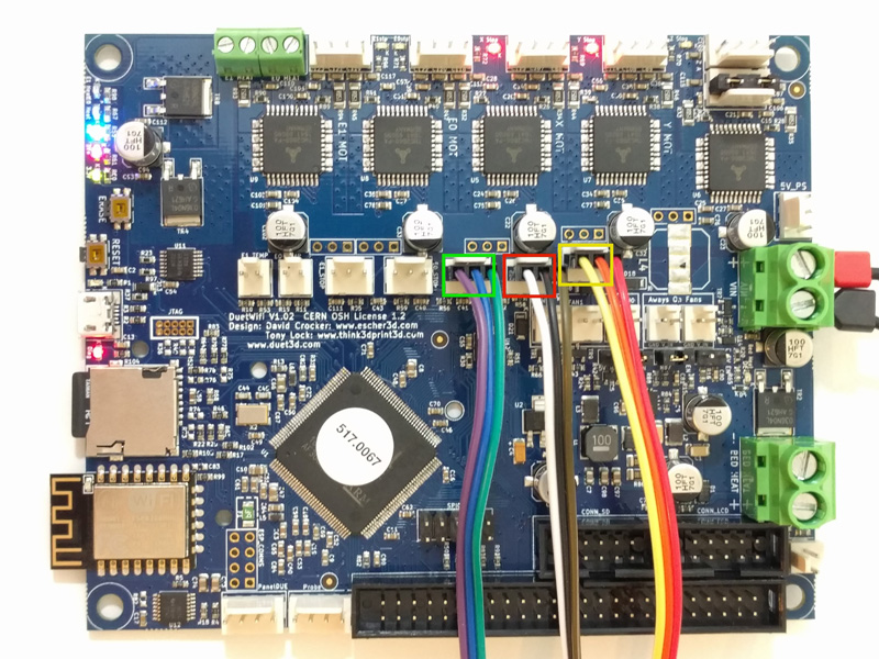
- Endstops tell the printer when the travel limit has been reached on a particular axis. The Duet's connections may be different from other controller boards, so please review this step and your endstops carefully.
- X Endstop
- Y Endstop
- Z Endstop
- From left to right on an endstop connector, the pins are signal (marked STP on the back of the board), +3.3v, and GND.
- If using 2 wire microswitch endstops, connect one wire to GND and the other wire to signal (STP), which are the outer two pins on the Duet connector.
- Never connect your endstop wires from +3.3v to ground. This will create a short circuit and could damage the Duet.
- If using other endstops, please refer to User manual: Connecting endstop switches for details.
¶ 11. Z Probe
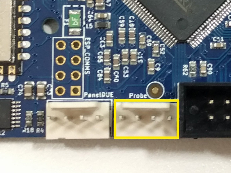
- The Duet supports a Z-probe via this dedicated connector. There are many different kinds of probe, and the wiring will be different for each one.
- See User manual: Choosing a Z probe, which will help you choose a suitable Z probe if you have not already.
- See User manual: Connecting a Z probe, which contains guidance for wiring your Z probe to the Duet.
¶ 12. Stepper motors
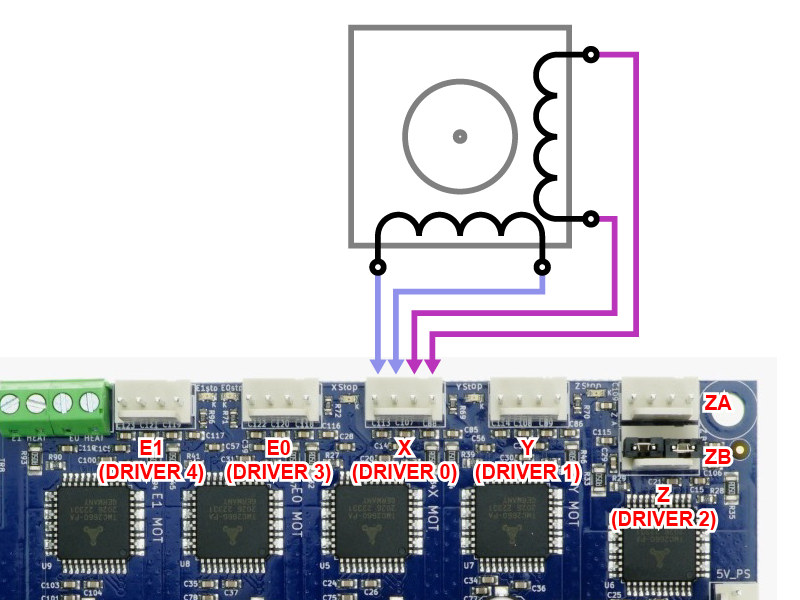
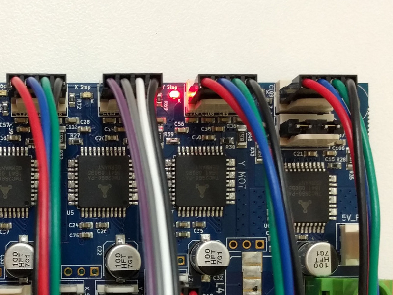
- The six four-pin connectors on the edge of the board are for stepper motors. From left to right they are labelled E1, E0, X, Y and Z. Z has two outputs.
- WARNING: You MUST connect the two wires for one phase of the stepper motor to the two pins at one end of the connector, and the two wires for the other phase to the two pins at the other end (see second image above). Incorrectly wiring the stepper motor may result in the failure of the stepper driver on the Duet. Do not assume your stepper motors are wired correctly! Please see User manual: Connecting stepper motors for more details and ways to identify the stepper motor phases.
- If you have only one Z-Axis stepper motor, plug it into the ZA connector and be sure that the supplied jumpers are installed on the ZB connector.
- If you have two Z-Axis stepper motors, connect them to ZA and ZB.
- ZA and ZB are wired in series; without a second stepper motor or the jumpers in place on ZB, ZA will not function.
- For the Duet 2 WiFi/Ethernet, if you need more than five stepper motors, you may use a DueX2 or DueX5 expansion board which offers 2 or 5 extra stepper motor outputs, respectively.
- For the Duet 2 Maestro, below the endstop connectors there are two headers for Dual Stepper Driver Expansion Module, which supports an additional two stepper motors.
- For more details, see User manual: Choosing stepper motors
- If you want to run external drivers, see User manual: Connecting external stepper motor drivers.
¶ 13. Fans
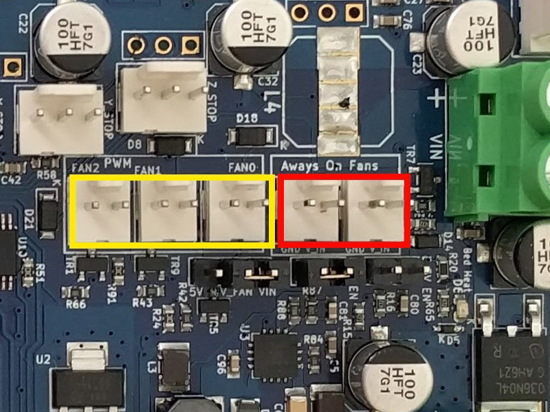
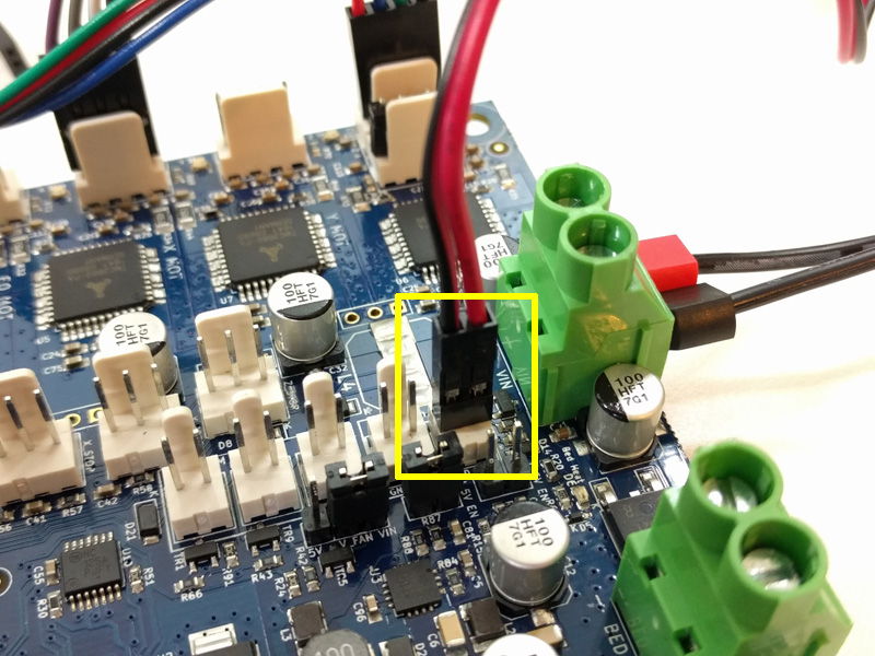
- The Duet has three PWM controlled fan headers (outlined yellow in the image above) and two Always On fan headers (outlined red).
- A PWM (Pulse Width Modulation) fan connection is for fans you wish to control the speed of, for example a print cooling fan.
- An always on fan is for something like an electronics fan - always on when the printer is on.
- Some fans are more compatible with PWM control than others. If you have trouble varying the speed of a fan, check the documentation for changing PWM frequency.
- The polarity of the fans is important - don't connect them backwards.
- For more details, see User manual: Connecting and configuring fans
- There are three PWM controlled fan headers and one Always On fan header. Voltage is selectable between VIN, 5V or external supply, in 2 banks. See the wiring diagram for details.
- A PWM (Pulse Width Modulation) fan connection is for fans you wish to control the speed of, for example a print cooling fan.
- An always on fan is for something like an electronics fan - always on when the printer is on.
- Some fans are more compatible with PWM control than others. If you have trouble varying the speed of a fan, check the documentation for changing PWM frequency.
- The polarity of the fans is important - don't connect them backwards.
- For more details, see User manual: Connecting and configuring fans
¶ 14. Bed Thermistor
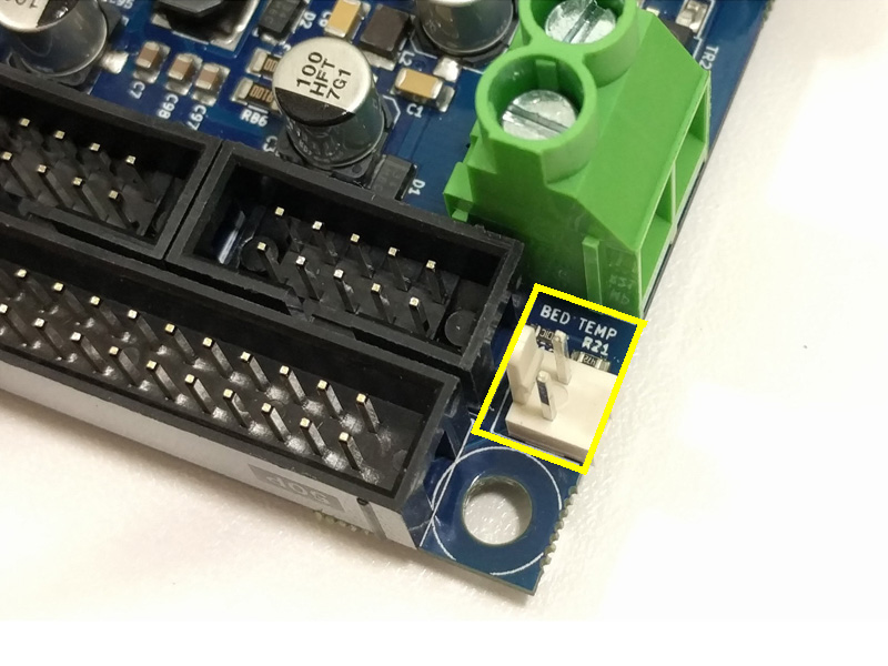
- Connect the bed thermistor to BED_TEMP (outlined yellow).
- The polarity of a thermistor does not matter.
- For more details, see User manual: Connecting thermistors and PT1000 temperature sensors.
¶ 15. Bed Heater
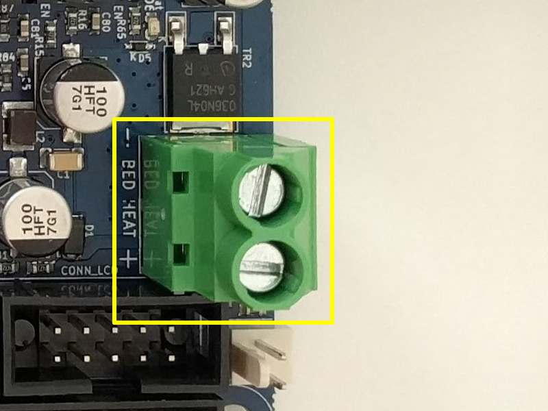
- The Duet is able to power a heated bed, and is fused at 15A. This should be well above the requirement for most heated beds.
- If your heater has an integrated LED, then the polarity will matter as the LED will not light with reverse polarity. Otherwise, a heater's polarity doesn't matter.
- WARNING: It is HIGHLY recommended to use the included ferrules, by crimping them to the wires before putting the wires in the terminal block. Failure to do so could allow the wires to creep over time, become loose, and could possibly short circuit and start a fire.
- Do not tin (add solder to) these wires.
- Be sure not to twist the terminal block while tightening the screws. It can help to hold the terminal block while tightening.
- Check the screws after a few days/weeks of operation to ensure they are still snug.
- For more details, see User manual: Connecting and configuring a bed heater.
¶ 16. Connecting a display
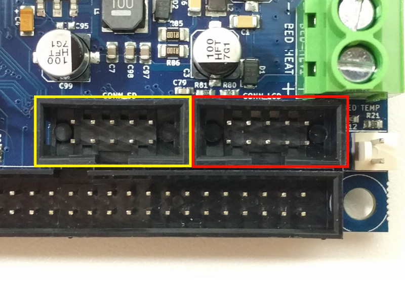
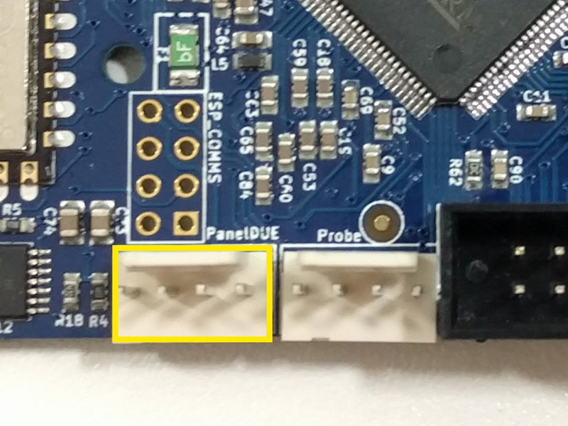 Two options exist for a directly-connected display for Duet 2 boards.
Connecting a PanelDue
Duet 2 WiFi/Ethernet supports PanelDue connected via CONN_LCD and/or PanelDUE connector.
Duet 2 Maestro supports PanelDue connected via 4-pin PanelDue connector or 10-pin PanelDue_SD connector
- The PanelDue, an optional accessory sold separately, is a touchscreen display which gives a user the ability to control the Duet with an intuitive interface directly at the printer.
- The PanelDue can be connected in two ways (both cables are supplied with the PanelDue), depending on Duet board:
- A 4-wire cable that contains power and serial signals. This has a maximum recommended length of 1 meter. It plugs into the 4-pin PanelDue header.
- A 10-way flat cable with a maximum recommended length of 400mm. It plugs into the 10-pin CONN_SD (Duet 2 WiFi/Ethernet) or PANELDUE_SD (Maestro) header. It has extra pins that allow the Duet to access the PanelDue's SD card reader.
- For more details, including using the PanelDue_SD header to connect an external SD card reader, see User manual: Connecting a PanelDue.
Connecting a 12864 display
Duet 2 WiFi/Ethernet RepRapFirmware 3.2 and later support a 12864 display using ST7567 controller. Uses CONN_LCD and CONN_SD. Requires modified wiring loom.
Duet 2 Maestro supports 12864 mono graphics LCD displays with a rotary encoder. The 12864_EXP1 and 12864_EXP2 connectors are used to connect a 12864 display.
- For details, see User manual: Connecting 12864 displays.
¶ 17. Expansion
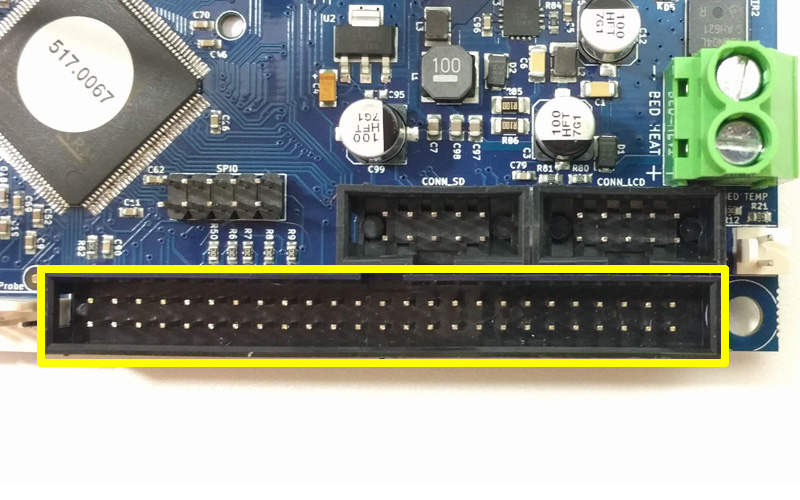

- The Expansion header (first image on right) is used to connect the Duet 2 WiFi/Ethernet to a DueX2 or DueX5 expansion board, or an Expansion Breakout Board (EBoB).
- The DueX2 and DueX5 expansion is an available add-on which offers additional stepper motor drivers, heater outputs, fan headers, endstop inputs, additional thermistor inputs, support for additional Temperature Daughterboards, and more.
- The Expansion Breakout Board (EBoB) is an available add-on which offers connections for external stepper drivers and hobby servos.
- The expansion connector can be used to connect other hardware directly; probes, stepper drivers, endstops, general purpose input/output, sensors and triggers. See User manual: Connecting hardware for details.
- The CONN_LCD header can be used for driving external stepper drivers, extra endstop and/or filament monitor connections, and connecting 12864 displays.
- The expansion header is used to connect other hardware directly; hobby servo, general purpose input/output, sensors and triggers. See User manual: Connecting hardware for details.
- The E2 and E3 External Driver pins can be used to control up to two external stepper drivers. Note that signalling levels are 3V. For details see User manual: Connecting external stepper and servo motor drivers
- Duet3D also offer a plug-in expansion board with two extra stepper drivers; for details, see Dual Stepper Driver Expansion Module.
¶ 18. Temperature Daughterboard
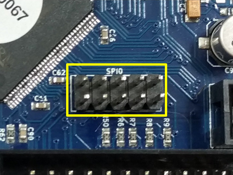
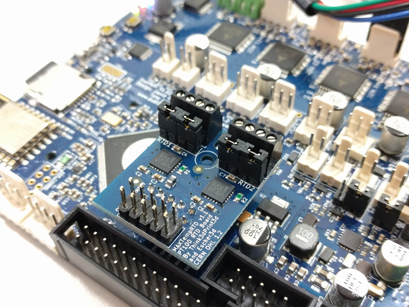
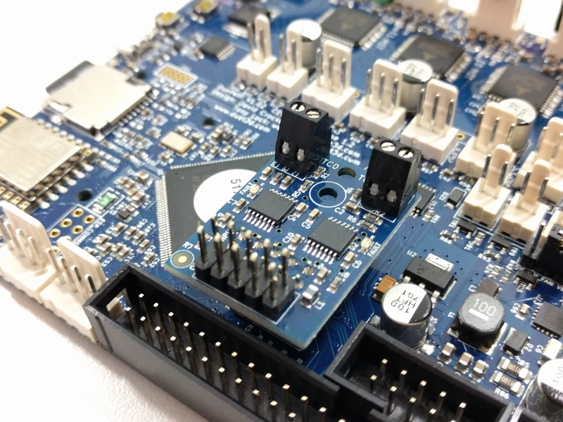
- The Temperature Daughterboard connector (labelled 'SPIO' or 'TEMP_DB') allows the Duet to connect with a thermocouple or PT100 temperature sensor, which send a different type of signal than a thermistor.
- Each daughterboard supports two additional temperature sensors of the same type, ie either 2x PT100 or 2x thermocouple.
- Duet 2 WiFi/Ethernet and Duet 2 Maestro boards supports up to two temperature daughterboards.
- A Temperature Daughterboard may be desired if, for example, you wish to print with materials which require greater than 290°C, which is the limit for a thermistor.
- If you plan to use PT100 temperature senesors, please read the wiki regarding the use of Temperature Daughterboards.
- For more details, see User manual: Connecting thermocouples and User manual: Connecting PT100 temperature sensors
¶ 19. WiFi or Ethernet Module
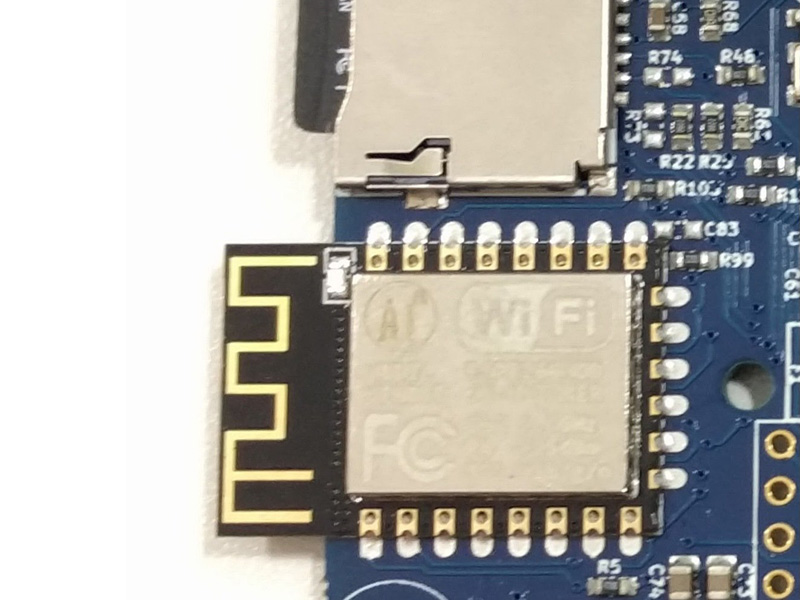
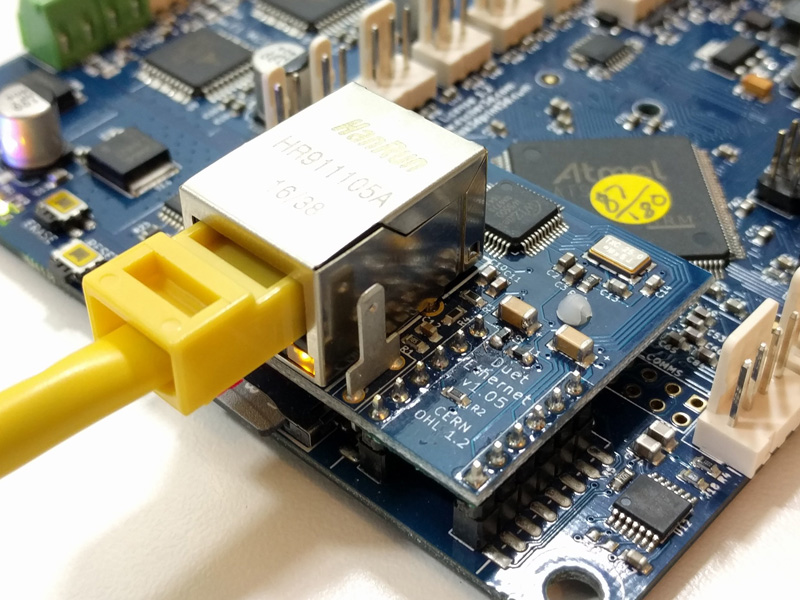
- Note: Duet 2 Maestro is Ethernet-only.
- The WiFi or Ethernet Module supports a connection over a web interface. It is responsible for a network connection.
- The WiFi module has a blue or green LED that indicates WiFi activity; flashing for searching/connecting, on for connected.
- If you have a WiFi module that uses an external antenna, there is also a U.FL external antenna connection; don't forget to plug in the external antenna!
- The Ethernet module has two LEDs on the RJ45 housing; Link, which is on when an ethernet connection is established, and Activity, which flashed whenever data is being actively transferred.
¶ 20. External 5V input and power supply control
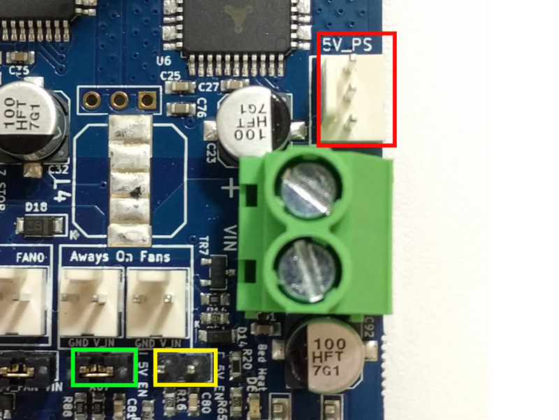
- The Duet has an on-board 5V regulator which is powered by the VIN input (12-24V).
- Unless you plan to provide an external 5v source, you should at this time check that there is a jumper on INT 5V EN and NOT on EXT 5V EN.
- Optionally, external 5V power can be provided to the board by moving the jumper from INT 5V EN to EXT 5V EN and supplying 5V power to the '+5V' pin of the EXT_5V or 5V_PS connector.
- The centre pin of the EXT_5V header, labelled PS_ON, can control an external power supply. The board can be powered from external 5V, with an external supply for VIN turned on and off as required. For more details, see User manual: Power wiring.
¶ 21. Troubleshooting
If your board does not power up after wiring:
- Check PSU is supplying expected voltage.
- Check for shorts in your wiring between VIN, 12V, 5V, 3.3V and ground (GND).
- Check fuses.
- Disconnect all wiring, check board powers up, then reconnect wiring one connector at time, powering down and back up between each reconnection, to identify wiring that is causing the short circuit.
- Some shorts, eg shorting VIN to 5V or 3.3V, will permanently damage the Duet. Shorting 5V or 3.3V to ground (usually mis-wired endstops) shouldn't cause damage, but will cause the Duet to not boot. See How to destroy your Duet 2.
¶ Wiring Complete!
Congratulations! Your Duet is wired and is ready to configure. Continue to the Configuring firmware guide to configure your Duet!
