¶ Introduction
The Duet 3 Tool Distribution Board is designed to simplify the connections of multiple Duet 3 Toolboard 1LCs and/or Duet 3 Roto Toolboards to the Duet 3 CAN-FD bus by providing breakout for CAN and power, bus pass-through and bus termination.
There was a major change between v0.5 and v1.0 to make wiring easier, especially of stubs.
¶ Features
- 2-way barrier strip for power in 12V-48V
- Four 2-way JST VH connectors for power out, individually fused (5A fuses supplied).
- Four 4-pin JST PA connectors to extend the CAN-FD bus in a daisy chain.
- Four 2-pin JST PA connectors to add devices on stubs
- Two RJ11 connectors for CAN bus in/out to connect to Duet 3 main board and expansion boards.
- Two 2-Pin JST PA connectors as alternative ports for CAN bus in/out
- CAN bus termination jumper pins.
- LED indication for Power In and per fused power output.
The Duet 3 Tool Distribution Board v1.0 is supplied with:
- 1x 0.5m RJ11 cable
- Fork terminals for power wiring
- JST PA crimps and 4-pin and 2-pin JST PA shells for CAN wiring.
- JST VH crimps and 2-way shells for power wiring.
- 2mm, 2-pin jumpers to bypass unused tool board CAN connectors and for CAN bus termination.
- M3 nylon washers for mounting
- 2-way barrier strip for power in.
- Four 4-pin JST ZH connectors to connect CAN bus to Tool Boards.
- Four 2-way JST VH connectors for power out to tool boards, individually fused (5A fuses supplied).
- Two RJ11 connectors for CAN bus in/out to connect to Duet 3 main board and expansion boards.
- CAN bus termination jumper pins.
The Duet 3 Tool Distribution Board v0.5 is supplied with:
- 1x 0.5m RJ11 cable
- Fork terminals for power wiring
- Four 4-pin JST ZH connectors with 1m cables to connect CAN bus to four Tool Boards. The cables supplied are 28AWG.
- JST VH crimps and 2-way shells for power wiring.
- Four pairs of 2-pin jumpers to bypass unused tool board CAN connectors.
- CAN bus termination jumper, for use if the CAN_OUT RJ11 port is not used.
- M3 nylon washers for mounting
¶ Operating limits
| Input power voltage | 12V to 48V (v1.0), 12V to 32V (v0.5) |
| Power input connector rated current | 20A maximum, or fused limit (whichever is lower) |
| Power output connector rated current | 5A for each tool power output |
| Fuses | 4x 5A fuses for each tool power output |
| Maximum ambient temperature | 70°C |
¶ Physical properties
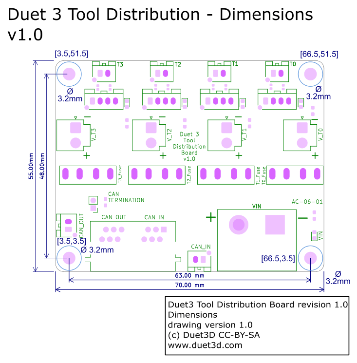
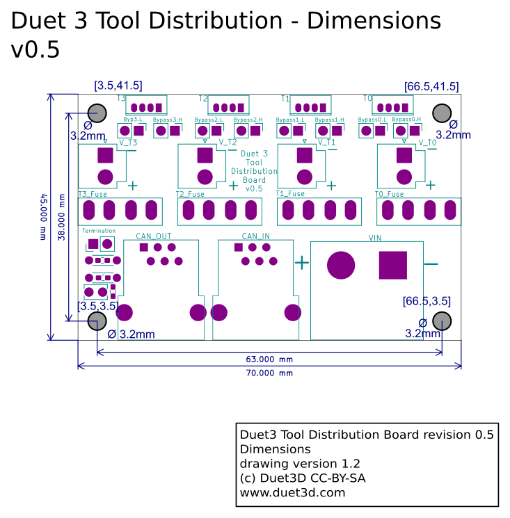
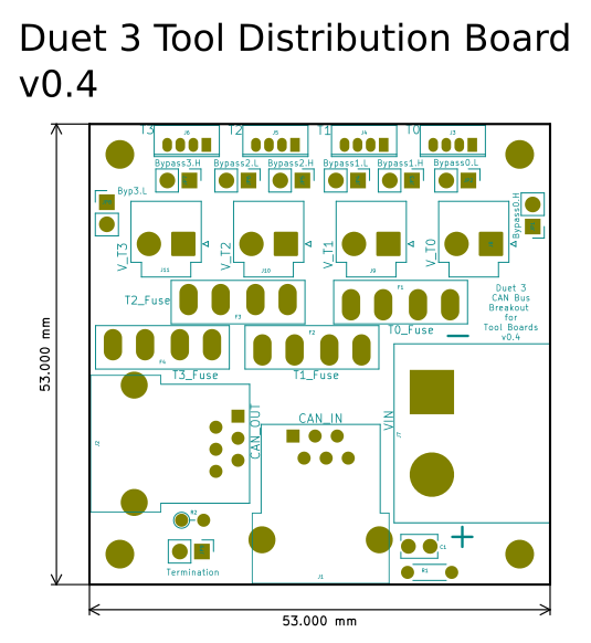
¶ Dimensions
¶ Physical connections
¶ Wiring diagram
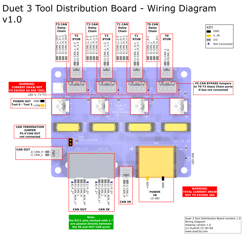
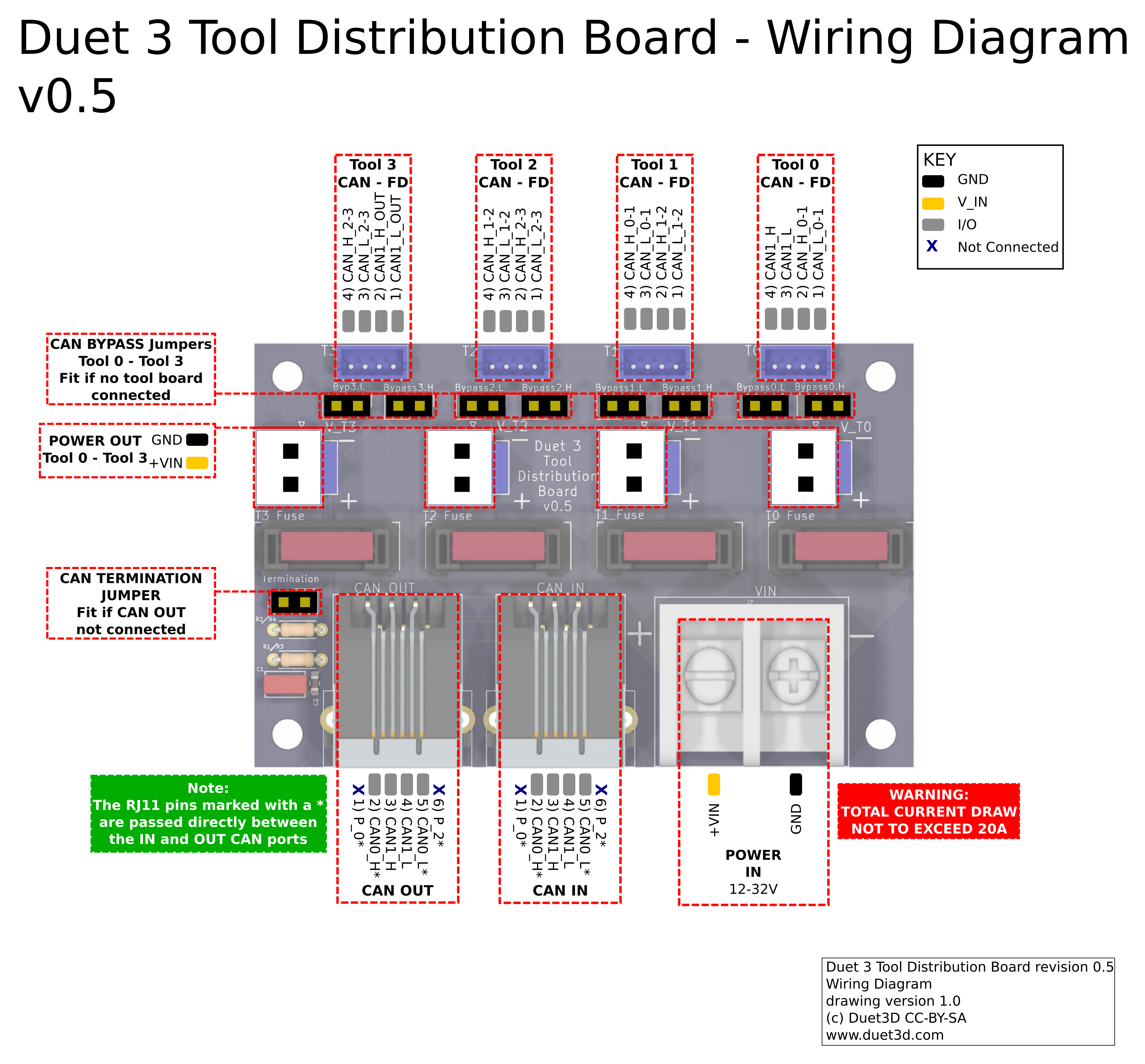
¶ Power distribution
Supply between 12V and 48V to the 2-way barrier strip power connector on the board, observing the correct polarity.
Use the four 2-way JST VH connectors for power out to tool boards. Each output is individually fused, with a supplied 5A fuse.
If you use a relay to control VIN power to the board, ie the power supply is already switched on, and a relay is used to turn on power to the board, you should use an inrush current limiter wired in series with VIN. See the section on Inrush current here.
OUT ports on the mainboard should NOT be used to switch power to expansion or tool boards directly. See the note at the end of the 'inrush current' section at the link above.
¶ CAN wiring
Also see CAN connection basics
The Tool Distribution Board provides flexibility in extending the CAN bus, offering a number of different ways to connect a range of two- and four-wire CAN bus expansion and tool boards.
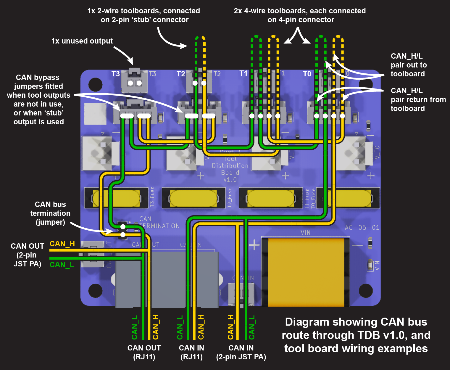
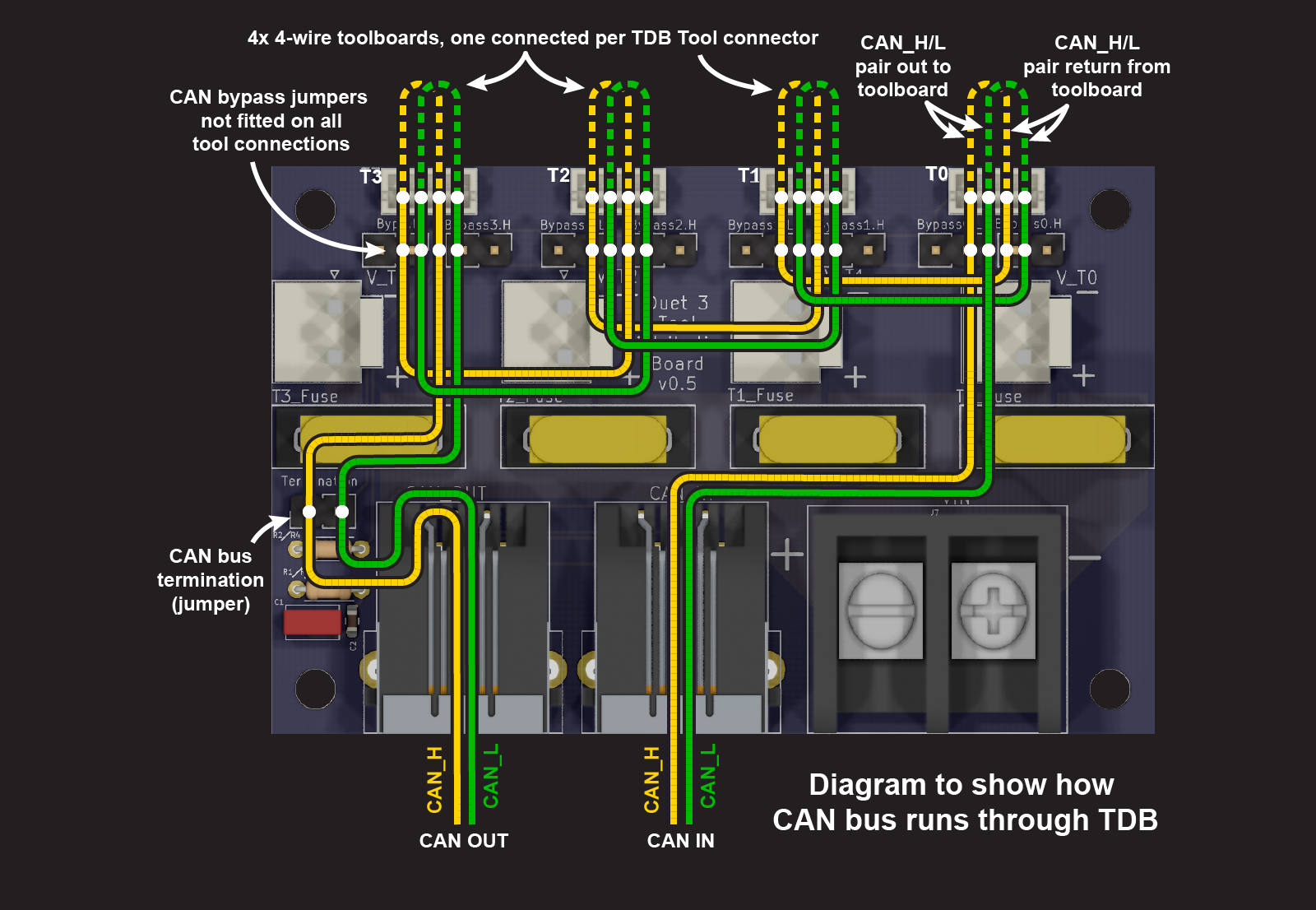
The Tool Distribution Board does this by extending the CAN bus internally.
¶ Connecting expansion and tool boards
Tool Distribution Board provides convenient places to connect either a loop in the CAN bus (4-wire connection) or a stub (2-wire connection). The type of connection can be mixed as necessary, so long as the continuity of the CAN bus is preserved.
For more information on CAN bus wiring schemes, see CAN connection basics.
¶ 4-wire connection
Expansion and tool boards that have a two pairs of CAN pins, or two RJ11 ports, can be connected as a loop in the CAN bus. This includes the Duet 3 1LC, 3HC, 1XD, 1HCL and M23CL.
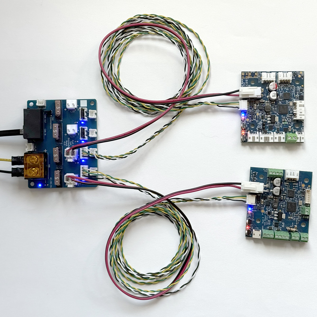 Originally, the Tool Distribution Board was developed to provide an easy way to connect Duet 3 Toolboard 1LC boards. Crimps and housings are supplied to make up cabling (see our wiring guide here). To connect:
- Remove the CAN bypass jumpers from the selected Tool output
- Connect a cable between the Tool Distribution Board and expansion or tool board
- Of the four wires, one pair carries the CAN bus to the tool board, and the other returns from the board, to loop on to the next tool output.
- Make sure CAN_H wires connect to CAN_H pins only, and CAN_L wires connect to CAN_L pins only.
- Up to four expansion or tool boards can be connected.
 As the Tool Distribution Board is just providing a convenient place to connect a loop in the CAN bus, multiple boards can be connected in each loop from the board.
- Remove the CAN bypass jumpers from the selected Tool output
- Connect a cable between the Tool Distribution Board and multiple boards
- The CAN loop extends from the CAN_OUT pair of pins of the Tool Distribution Board, through each expansion board, and back to the CAN_IN pair of pins.
- Make sure CAN_H wires connect to CAN_H pins only, and CAN_L wires connect to CAN_L pins only.
- This allows for more than one board to be connected per tool connection, and more than four boards in total.
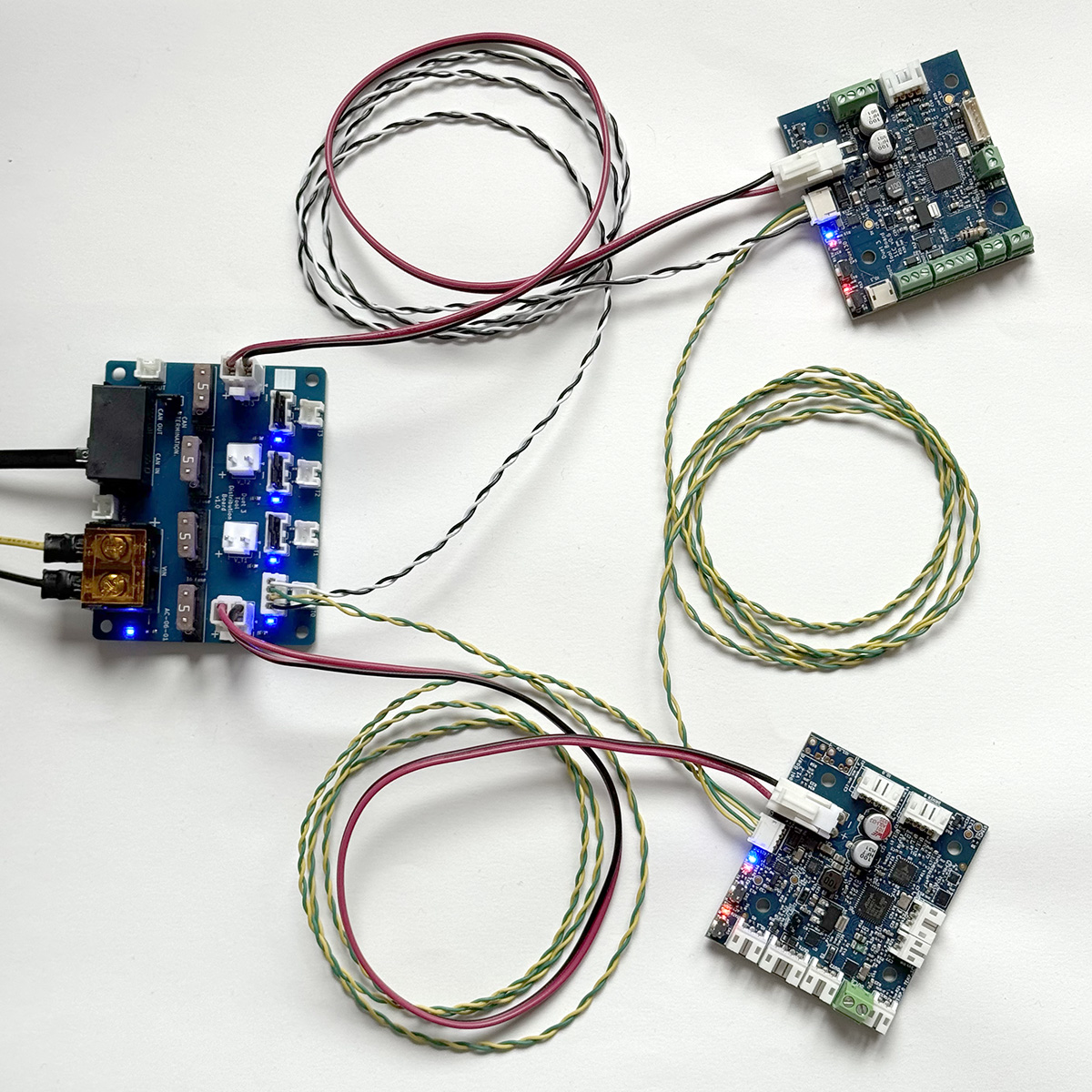
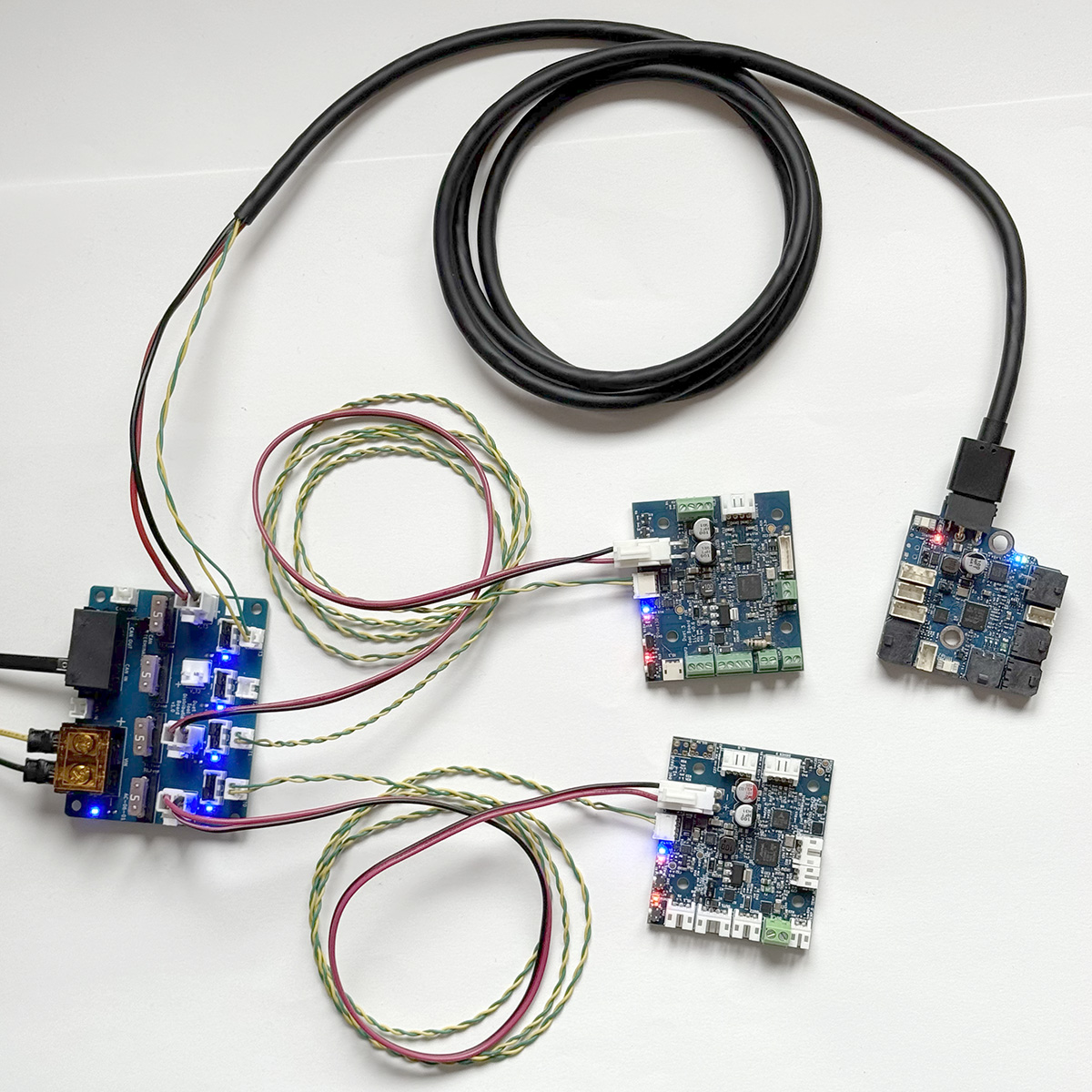
Boards with a 2-pin only connection, eg Duet 3 Roto toolboard, Scanning Z Probe, and mainboards when used as an expansion board, can use a 4-wire connection, by wiring a loop of CAN wires, and having a short 'stub' of a pair of wires off the loop, connected to the board.
Expansion and tool boards that have a two pairs of CAN pins, or two RJ11 ports, can be connected as a loop in the CAN bus. This includes the Duet 3 1LC, 3HC, 1XD, 1HCL and M23CL.
 Originally, the Tool Distribution Board was developed to provide an easy way to connect Duet 3 Toolboard 1LC boards. The supplied cables connect directly to that board, but can be adapted to connect other 4-wire boards. To connect:
- Remove the CAN bypass jumpers from the selected Tool output
- Connect the cable between the Tool Distribution Board and expansion or tool board
- Of the four wires, one pair carries the CAN bus to the tool board, and the other returns from the board, to loop on to the next tool output.
- Make sure CAN_H wires connect to CAN_H pins only, and CAN_L wires connect to CAN_L pins only.
- Up to four expansion or tool boards can be connected.
 As the Tool Distribution Board is just providing a convenient place to connect a loop in the CAN bus, multiple boards can be connected in each loop from the board.
- Remove the CAN bypass jumpers from the selected Tool output
- Connect the cable between the Tool Distribution Board and multiple boards
- The CAN loop extends from the CAN_OUT pair of pins of the Tool Distribution Board, through each expansion board, and back to the CAN_IN pair of pins.
- Make sure CAN_H wires connect to CAN_H pins only, and CAN_L wires connect to CAN_L pins only.
- This allows for more than one board to be connected per tool connection, and more than four boards in total.
Boards with a 2-pin only connection, eg Duet 3 Roto toolboard, Scanning Z Probe, and mainboards when used as an expansion board, can use a 4-wire connection, by wiring a loop of CAN wires, and having a short 'stub' of a pair of wires off the loop, connected to the board.
¶ 2-wire connection
Some expansion and tool boards only have a two-pin CAN connection, eg Duet 3 Roto toolboard, Scanning Z Probe, and mainboards when used as an expansion board. This necessitates a two-wire connection. Though actually all expansion, tool, and mainboards-as-expansion boards can be connected using just two CAN wires. This is like a branch off the main CAN bus, and is called a 'stub'. There are some rules to stubs:
- The maximum recommended stub length for the 1Mbit/sec signalling rates used by Duet is 1m, and should preferably use ferrite beads to suppress ringing.
- Stubs can have multiple boards on them, but the total length of the stub should still not be more than 1m.
- The total length of all stubs should not be more than 5m.
- The CAN bus on Duet 3 boards normally runs at 1Mbit/sec by default. If the bit rate is increased using M952, signal reflections caused by stubs will be more significant, making it more important to keep stubs short and/or use ferrite beads.
- Stubs can be mixed with daisy-chaining to create the CAN bus that best suits your requirements.
- Do not terminate the CAN bus at the end of a stub, unless it is the last, or only, stub.
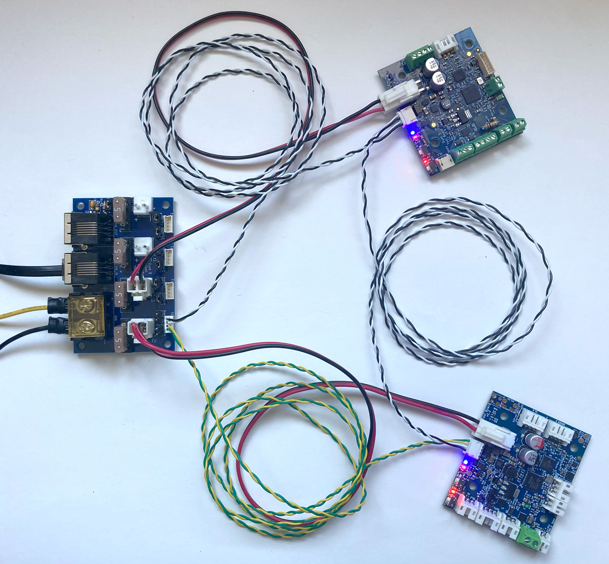
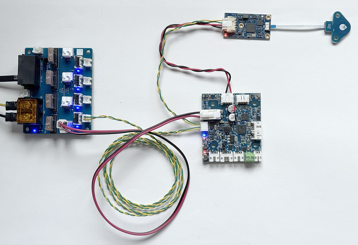
 To connect a stub to the Tool Distribution Board:
- Fit both CAN bypass jumpers to the selected Tool output
- Connect a 2-wire cable between the Tool Distribution Board 2-pin CAN output and the expansion or tool board
- Make sure CAN_H wires connect to CAN_H pins only, and CAN_L wires connect to CAN_L pins only.
- The Tool Distribution Boards can support up to four boards directly connected in this way, but make sure the total length of the stubs is less than 5m.
 Stubs can support more than one board, so long as the total length of the stub is under 1m.
Some expansion and tool boards only have a two-pin CAN connection, eg Duet 3 Roto toolboard, Scanning Z Probe, and mainboards when used as an expansion board. This necessitates a two-wire connection. Though actually all expansion, tool, and mainboards-as-expansion boards can be connected using just two CAN wires. This is like a branch off the main CAN bus, and is called a 'stub'. There are some rules to stubs:
- The maximum recommended stub length for the 1Mbit/sec signalling rates used by Duet is 1m, and should preferably use ferrite beads to suppress ringing.
- Stubs can have multiple boards on them, but the total length of the stub should still not be more than 1m.
- The total length of all stubs should not be more than 5m.
- The CAN bus on Duet 3 boards normally runs at 1Mbit/sec by default. If the bit rate is increased using M952, signal reflections caused by stubs will be more significant, making it more important to keep stubs short and/or use ferrite beads.
- Stubs can be mixed with daisy-chaining to create the CAN bus that best suits your requirements.
- Do not terminate the CAN bus at the end of a stub, unless it is the last, or only, stub.
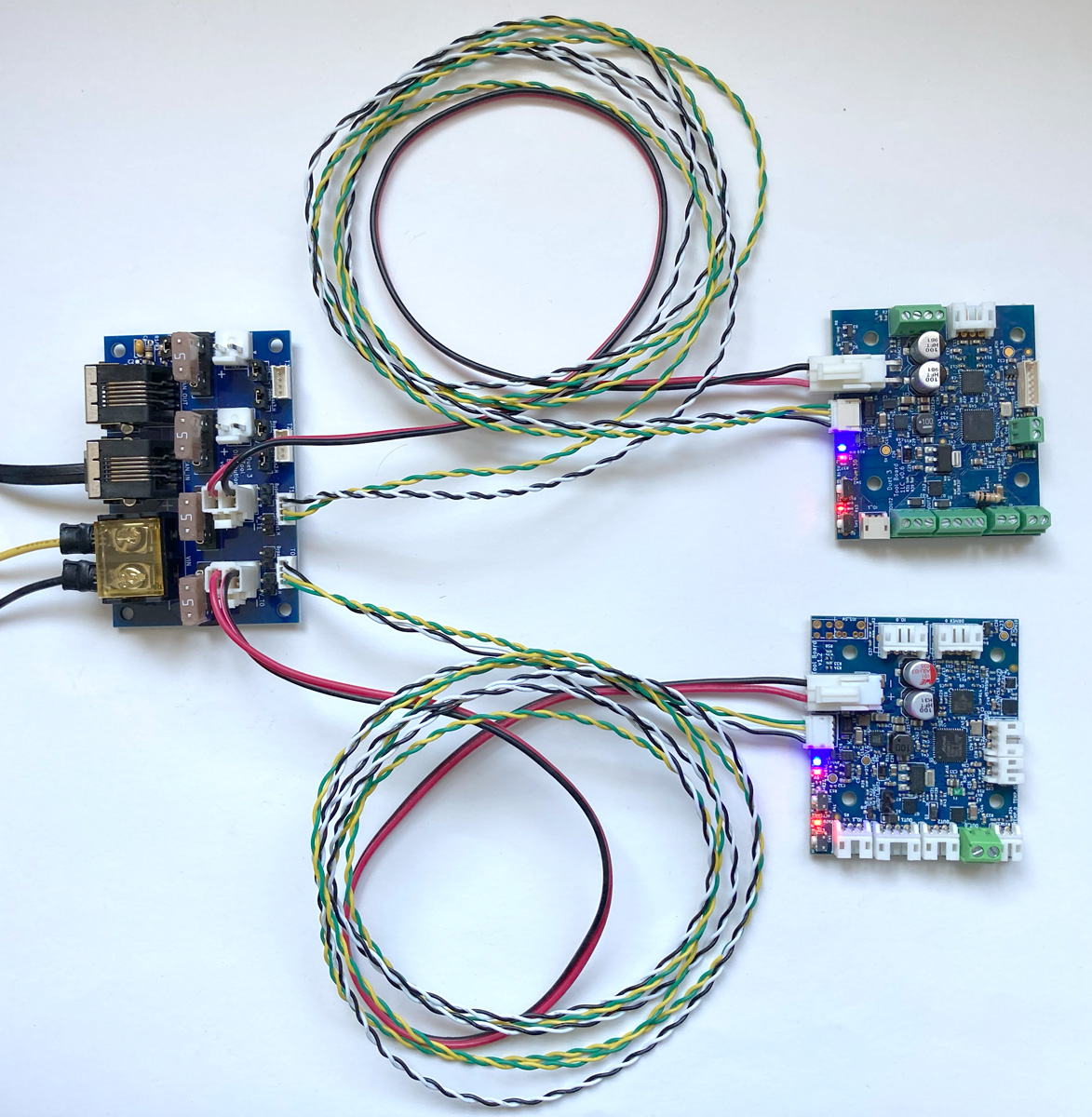
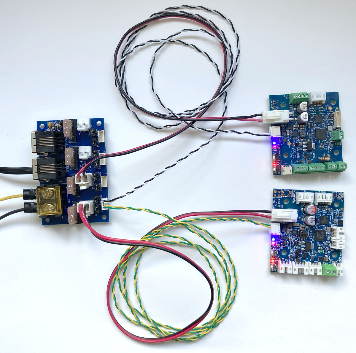 To connect a stub to the Tool Distribution Board:
- Fit both CAN bypass jumpers to the selected Tool output
- Connect a 2-wire cable between the Tool Distribution Board and the expansion or tool board
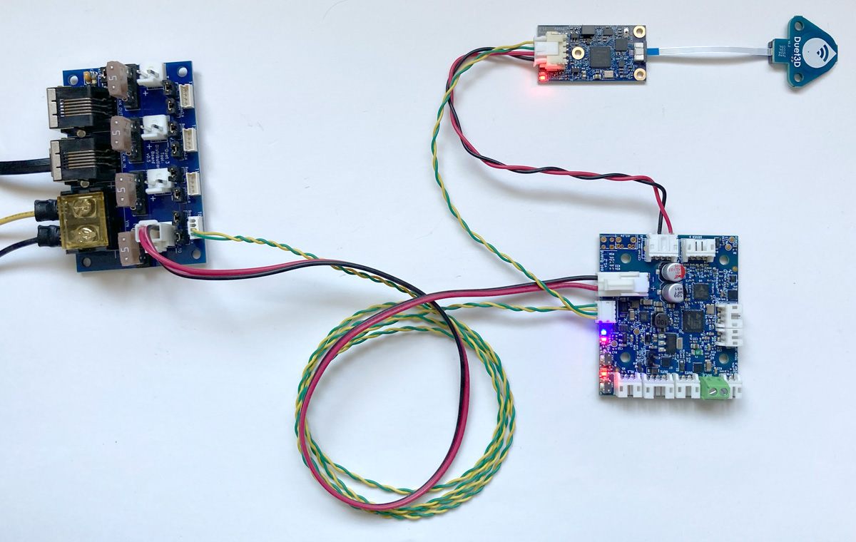
- Use either pair of pins for one board, or both for two boards (as in the images to the right)
- Make sure CAN_H wires connect to CAN_H pins only, and CAN_L wires connect to CAN_L pins only.
- The Tool Distribution Boards can support up to eight boards directly connected in this way, but make sure the total length of the stubs is less than 5m.
 Stubs can support more than one board, so long as the total length of the stub is under 1m.
¶ Unused tool connections
If no expansion or tool board is to be connected to a tool connector, leave the CAN bypass jumpers in place. This allows the CAN bus to continue on to the next tool connector, to the termination jumper, or the CAN OUT RJ11 connector.
¶ Termination
CAN bus termination is required at each end of the CAN bus. The mainboard, usually at one end, supplies the termination there. So long as the continuity of the bus is maintained through the Tool Distribution Board (ie with bypass jumpers or wiring tool/expansion board with a 4-wire connection), the CAN bus can be terminated on the Tool Distribution Board.
Alternatively, you can put the termination on the last toolboard on the Tool Distribution Board.
If there are further CAN expansion boards connected via the RJ11 CAN OUT connector, remove the termination jumper from the Tool Distribution Board.
¶ Revisions
- Change 4 way can headers from JST ZH to JST PA.
- Add 2 ways JST PA headers designed for connecting CAN stubs.
- Change to a double RJ11 header for manufacturability
- Change to 2mm can termination jumper for compatibility with 2mm jumpers used to bypass 4 pin headers.
- Add power LEDs per power output, and one on the input.
- First production version.