¶ Introduction
This document is relevant to: All Duet boards
Firmware versions: All versions
Difficulty: Moderate
Time Required: 30 minutes - 1 hour
This guide covers configuring RepRapFirmware for your machine.
If you have any problems with your Duet when using this guide, rather than posting comments, please use our support forum: https://forum.duet3d.com/
¶ 1. Turn on power
If you have just changed your configuration, and the Duet has rebooted with mains power, IMMEDIATELY check that your new configuration is not heating heaters/moving axes/starting spindles or any other unexpected and unwanted behaviour. If it is, TURN OFF THE POWER! You can investigate any problems and check configuration by powering the Duet with USB power only.
¶ 2. Connect to Duet Web Console (DWC)
If you changed the machine name in the RepRapFirmware Configurator, this will be reflected in the .local address. For instance, if you named the machine "My Printer", you will navigate to myprinter.local/ (without spaces and not case sensitive).
Open your browser and navigate to yourduetname.local or the IP address you set.
If you have trouble finding the IP address of the Duet, you can:
- Connect to your Duet via USB. Send M552 to see the network configuration and IP address.
- Login to your router; it should be able to show a list of connected devices
- Use a network scanning app to show the connected devices on the network.
You will be using Duet Web Console (DWC) for most of the commissioning; see User manual: Duet Web Console for a full introduction to the interface.
¶ 3. First check
A good first check is to see if there are any errors in your configuration, by testing your config.g. You can do this by running the config.g, and any errors will be reported. In DWC go to the Control > Console option, and type in M98 P"config.g". This can also be sent from a USB-connected serial terminal. This will re-run your config.g. Note that it is best to run this command after a reset or power on, because if you have sent any commands to change settings, this will reset them.
A normal console output may look like this:
M98 P"config.g"
HTTP is enabled on port 80
FTP is disabled
TELNET is disabled
You may receive errors that look like these; comments after are added to help fix them:
Error: Unknown pin name 'duex.e1heat' ; incorrect pin name, see the 'Pin names' section of your boards hardware info page
Error: Heater 1 not found ; If the M950 command that defines a heater is incorrect, no heater is created, all subsequent commands referring to it generate an error
Error: Heater 1 does not exist ; see above
Error: Sensor 4 does not exist ; M950 heater definition includes a reference to a sensor that hasn't been configured
Error: Bad command: mp"" Y"thermistor" T100000 B4138 ; Related to the above, the M308 line defining the sensor is incorrect
Error: in file macro line 108: M308: missing parameter 'S' ; as above
Error: Heater 4 not found ; With the M308 and M950 command not correct, no heater is created, all subsequent commands referring to it generate an error
Error: Heater 4 does not exist ; as above
Error: Unknown pin name 'duex.fan0' ; Incorrect fan pin name, see the 'Pin names' section of your boards hardware info page
Error: Fan number 0 not found ; If the M950 command that defines a fan is incorrect, no fan is created, all subsequent commands referring to it generate an error
Warning: Heater 0 predicted maximum temperature at full power is 403°C ; This is just a warning, not necessarily an error. It is usually due to M307 parameters for that heater, and often that the heater has not been tuned, but also the heater might just be able to get that hot!
Depending on the error reported, check Gcode in your config.g and fix the error.
You can use M98 P"config.g" any time to check your config.g, and is a useful diagnostic tool.
¶ 4. Check thermistors
To get accurate temperatures, you must configure temperature sensing correctly for the type of temperature sensor you are using. The default values in the RepRapFirmware Configuration Tool are unlikely to be correct!
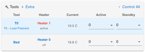 On the 'Control > Dashboard' page of DWC, in the Tools section, check the 'Current' temperature reading on each heater. Each heater is configured to be either a Tool, Bed or Chamber, eg "T0", "Bed".
- It should be around room temperature if the heaters have not recently been on.
- It is OK if there's a few degrees of error as thermistor readings have better resolution at higher temperatures.
Troubleshooting
If you get a temperature reading of "-273°C", this indicates an open circuit, i.e. nothing is connected to the defined pins.
- Check that the temperature sensor is connected to the correct pins
- Check the wiring for breaks
- Measure the resistance of the wires that connect to the Duet, and that it corresponds with what the firmware expects
- Check that the configuration is set correctly for the temperature sensor.
If you get a temperature reading of "2000°C", this indicates a dead short between the temperature sensor pins on the Duet, or mis-configured firmware.
- Check your M305/M308 configuration
- Check the wiring isn't grounding out to something
Further reading
See User manual: Connecting thermistor and PT1000 temperature sensors and M308 (RRF 3.x) or M305 (RRF 2.x) for more details.
¶ 5. Check fans
 Next, check the fans are operating correctly.
Always On fans
Always On fans should already be on. Check them at this time.
Part cooling fans
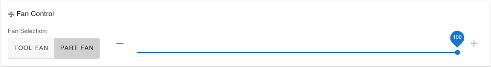
Test fans in DWC with the Control > Dashboard > Fan Control slider:
- If you have a fan that is connected as FAN 0 (usually the part cooling fan), you can use the Fan Control slider to check it works.
- 'TOOL FAN' is the currently-activated tool's part cooling fan. It will only show when a tool is active.
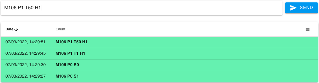
Test fans by entering GCode commands directly:
- In DWC, go to Control > Console.
- In the box under Status section, enter the following command then press return to send it to the Duet:
M106 P0 S1. The S parameter sets the fan speed, where 0 is off and 1 is on 100%. - Turn it off by sending
M106 P0 S0.
Thermostatically controlled fans
Thermostatically controlled fans are not displayed on the Fan Control slider. But we can check them by temporarily changing the temperature at which they activate.
- In DWC, go to Control > Console.
- In the box under Status section, enter the following command then press return to send it to the Duet:
M106 P1 T1 H1. The T parameter sets the temperature the fan comes on at. - To turn it off, send
M106 P1 T50 H1 - P1 is for Fan 1. If you have more thermostatically controlled fans, repeat this step after changing P1 to P#, where # is the fan number.
Further reading
See User manual: Connecting and configuring fans and GCode M106 for more details.
After confirming the operation of the fans, to reset the configuration you can either press the "Reset" button on the Duet, or send
M999, or re-run config.g by sendingM98 P"config.g"in 'Control > Console'.
¶ 6. Check heater functionality
 Manually controlling heaters
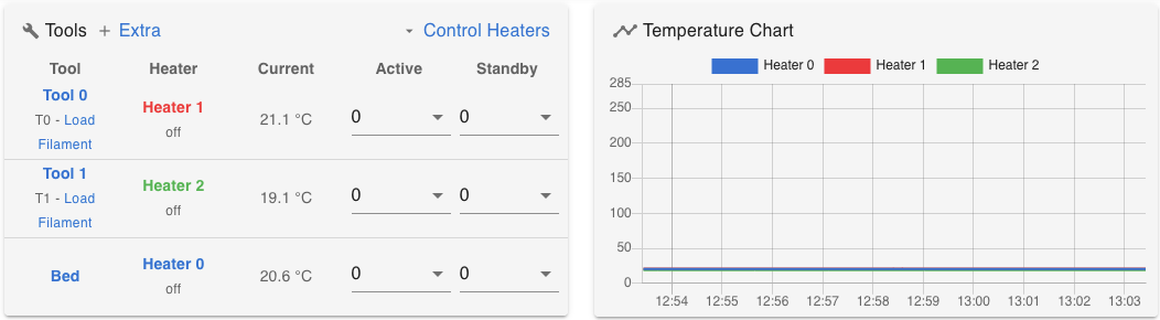
On the Dashboard page, the Tools section lists the tools, bed heaters and chamber heaters. The Temperature Chart shows the heater temperature over time.
The firmware allows one tool to be selected/active at a time. The associated heater(s) is/are set to 'active' when the tool is selected, and set to 'standby' when the tool is deselected. However, tool heaters can also be manually controlled, independently of tools.
Under the first 'Heater [#]' (where # is the heater number) it should say 'off', 'standby' or 'active'.
- Clicking the associated tool name (eg 'T0' in the Tool column) will cycle the heater between 'active' and 'standby', as the tool is selected and deselected. The target temperature for each state is set by the associated Active and Standby temperature.
- Clicking the heater name (eg 'Heater 1' in the Heater column) will cycle the heater between 'active', 'standby' and 'off'. The heater can be controlled independently of the tool state.
- Bed and Chamber heaters are controlled more directly, and cycle through 'active', 'standby' and 'off' whether you click the name or the heater number.
Testing heaters
WARNING: If you enable the heater but do not observe an increase in the temperature reading, turn off the controller immediately and check your wiring.
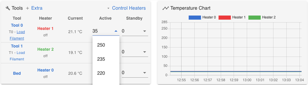
 Enter a number in the "Active" box for the first tool, or choose an appropriate temperature from the drop-down list. Start off with a low number such as 35°C. Press return to set this temperature.
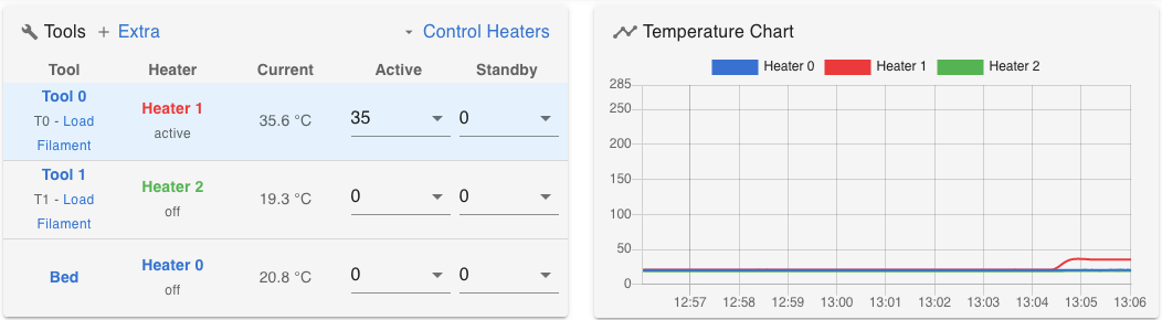
- If the heater is already set to 'active', you should see the corresponding temperature begin to rise.
- If the heater is set to 'standby' or 'off', DWC does not automatically activate it when temperature is set. Click the tool name or heater name until the heater is 'active'.
With the heater set to 'active', you should see the corresponding temperature begin to rise, and this will show on the temperature chart. It is possible that it will overshoot the set temperature a bit; this is OK.
You can also check that thermostatically controlled fans are working as expected, by setting a heater temperature higher than the trigger temperature for the fan, eg 60°C.
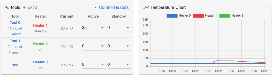
Complete this step by clicking the tool, bed or chamber name, or the heater name, to set the tool/heater into 'standby' or 'off'.
Repeat this step for the rest of the tool, bed and chamber heaters. Bed and chamber heaters usually take much longer than nozzle heaters to heat up and cool down, so you can set their active temperature lower to test.
Troubleshooting
You may receive errors such as "Error: Heater [heater #] fault: temperature rising too slowly". This is usually because the firmware does not have an accurate model of how the heater responds. You will need to 'tune' the heaters, which is covered in the next section.
- Click on the tool, bed or chamber name, or the heater name, to reset the heater fault. DWC will pop up a stern warning with a timer, and allow you to reset the fault after a few seconds. You can also send M562 to reset temperature faults.
¶ 7. Tune heaters
 It is recommended that you 'tune' your heaters after ensuring their functionality. This gives the firmware an accurate model of how your heater responds, so it can spot if something goes wrong. Make sure that your temperature sensors are configured correctly and reporting sensible temperatures first!
If you have received a temperature error and a heater is marked as 'fault', click on the tool, bed or chamber name, or the heater name, to reset the heater fault. DWC will pop up a stern warning with a timer, and allow you to reset the fault after a few seconds. You can also send M562 to reset temperature faults.
Tuning heaters
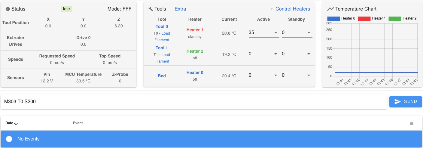
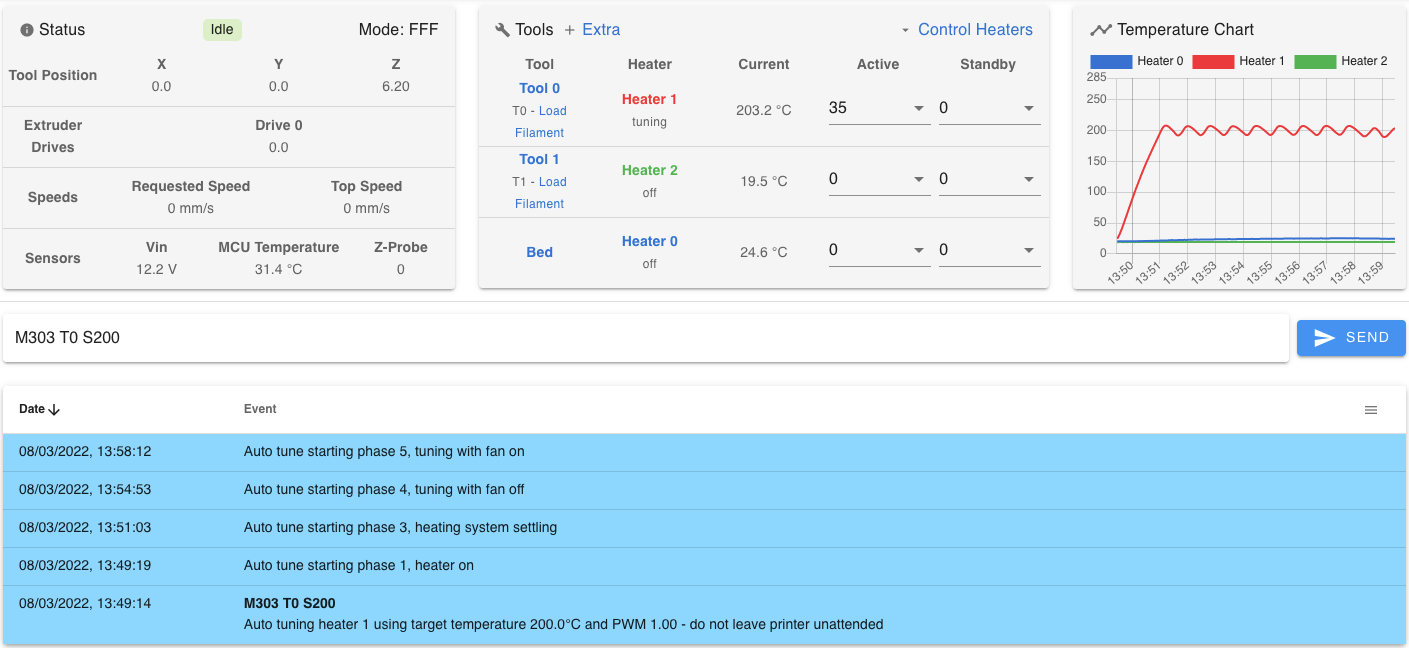
To tune heaters, use the M303 GCode command.
- Heaters must be at room temperature before starting tuning.
Tune tool heaters first. In Control > Console, send M303 T0 S200 where 'T' is the tool number, and 'S' is the target temperature. Tuning a tool heater usually takes around five to ten minutes.
- When tuning a heater as a tool, the tuning tests the effect of the part cooling fan, and modifies the parameters for when the part cooling fan is on. To mimic the effect of printing, move the hot end so the nozzle is around 1mm above the bed. If you haven't tested moving the motors yet, you can move the hot end SLOWLY by hand.
- In some circumstances, you may just want to tune the heater of a tool, without tuning for the effect of the fan. In this case, send
M303 H1 S200, where 'H' is the heater number.
To tune a bed or chamber heater, send M303 H0 S60 where 'H' is the heater number for the bed or chamber, and 'S' is the target temperature. Tuning these heaters can take a long time, possibly up to 2 hours, as the heater needs to go through a number of heating and cooling cycles. The bigger the heater, the longer this takes.
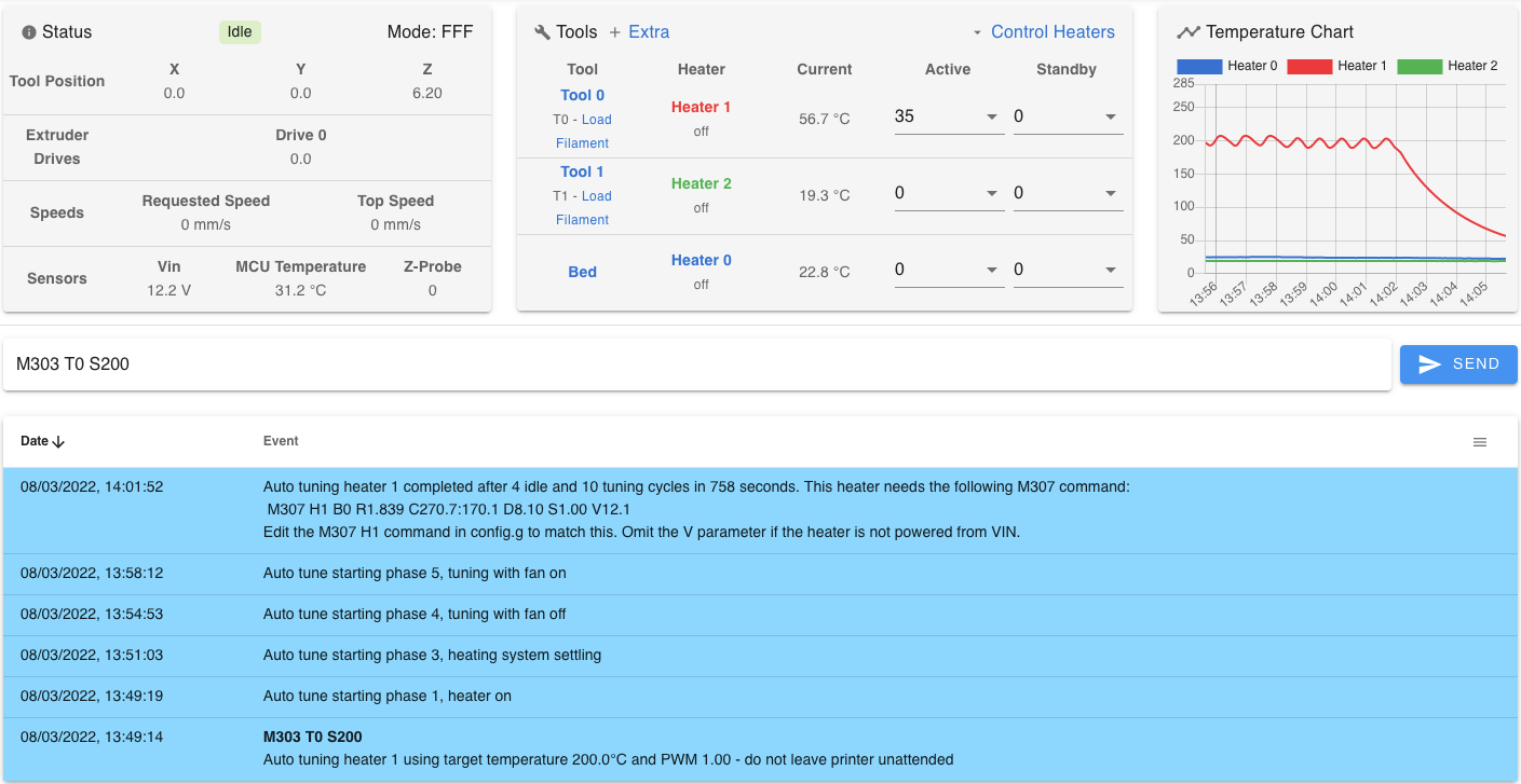
Result
If successful, the firmware will report the parameters to use, and an M307 GCcode command e.g.:
M307 H1 R7.046 K1.519:0.006 D3.58 E1.35 S1.00 B0 V23.9 (RRF 3.4 and later)
M307 H1 B0 R1.839 C270.7:170.1 D8.10 S1.00 V12.1 (RRF 3.3 and earlier)
Then, either:
- Copy this into your config.g, replacing the existing one for the heater, or
- If your config.g has M501 at the end, you can save the current heater settings by sending M500. This will save the current parameters to the sys/config-override.g on the SD card. M501 in config.g will load them at each reboot.
If you need to 'hot-tighten' your hot end nozzle, now is a good time to do it. Set the Tool heater active temperature to the temperature specified by the manufacturer and click the tool name to set the tool to active. Once finished, click the tool name to turn off the heater.
After confirming the operation of the heaters and to save and implement the changes you have made, you need to reset the Duet. If you edit then save the config.g, DWC should ask if you want to reset the Duet or re-run config.g. You can also press the "Reset" button on the Duet, or send
M999, or re-run config.g by sendingM98 P"config.g"in 'Control > Console'.
Troubleshooting and further reading
If you encounter any errors, see User manual: Tuning the heater temperature control for more details.
¶ 8. Check Endstops
Never connect endstop wires from +3.3v to ground. This will create a short circuit and could damage the Duet.
When 'homing' your machine, each axis will move towards the end of its travel. It expects to trigger a switch, which will set the axis location. Simple microswitches, hall sensors or optical sensors can be used.
- Check that your endstops are configured correctly by sending
M574in the console. - It is important that you check that the Duet is receiving a signal from your endstops, if you have them fitted. Failure to do so could cause damage to your printer!
- You want the firmware to report them as 'not stopped' when they are not triggered, and 'at max/min stop' when they are triggered.
- On Duet 2 WiFi/Ethernet, there is an endstop status LED between each motor driver.
You can check the status of your endstops a number of ways:
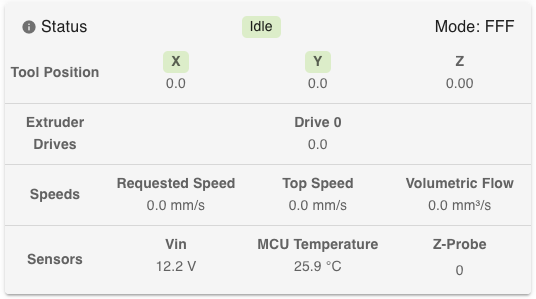 In DWC v3.5 and later, the endstop status is indicated in the Status panel. If the endstop is triggered, a green square will highlight the axis that is triggered. If there is no green square, it is not triggered.
- Press and hold each endstop switch, and check the axis label changes colour.
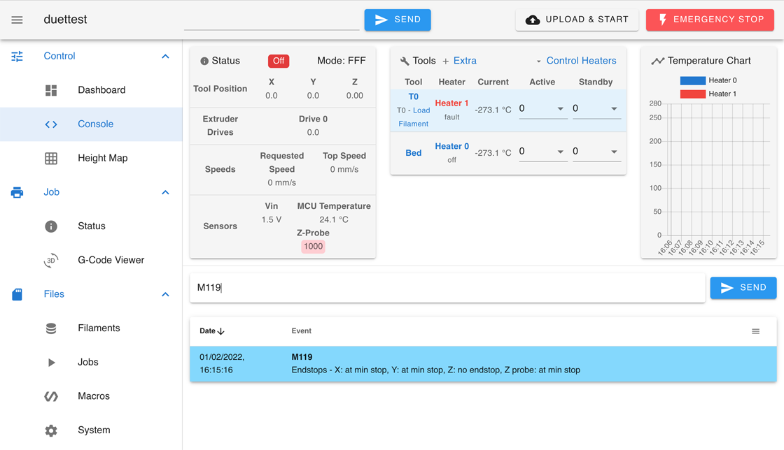 Send M119 to check endstop status in all versions of DWC/RRF. This can be sent from DWC, a PanelDue, or over USB, if connected by serial terminal.
- In DWC, go to Control > Console and type in
M119in the text box, then press return or the 'Send' button. You should get the endstop status response in the area below. - If connected to the Duet by a serial terminial over USB, type
M119and press return; the Duet will respond with the endstop status. - Press and hold an endstop switch, and sent the command again, and you should see the status response of that switch change.
 You can check the endstops status in the DWC Object model browser in RRF/DWC v3.0 and later. The RepRapFirmware Object model shows all the firmware variables and values.
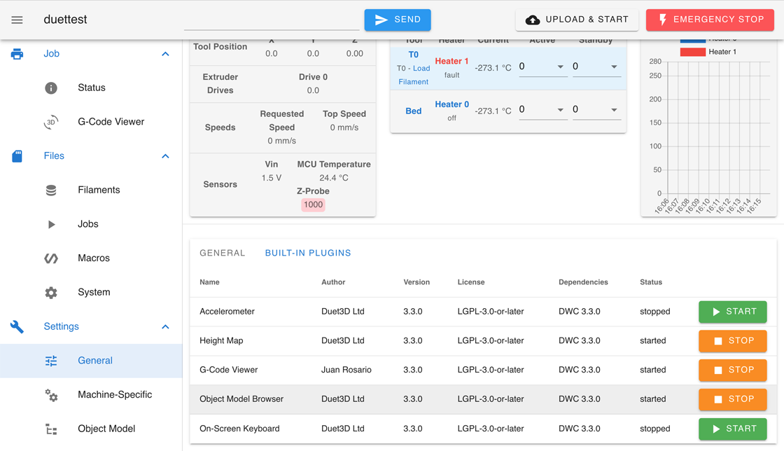
- Enable the Object model browser by going to 'Settings > Plugins > Integrated plugins' ('Settings > General > Built-in Plugins' in older versions of DWC) and click 'Start' on the 'Object Model Browser'.
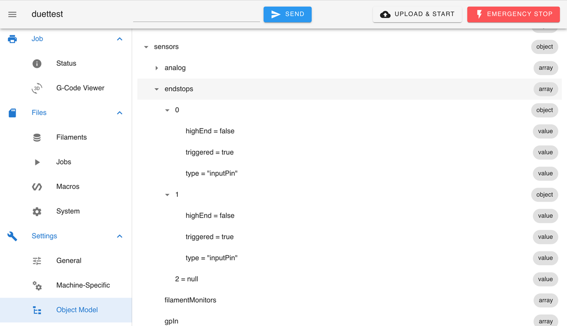
- A new menu option 'Object Model' will appear; select it.
- Navigate to 'sensors > endstops'. Expand the numbered sections. Trigger an endstop, and it will show as 'triggered = true' if correctly configured.
 In DWC v3.3 and v3.4, you can also install a plugin to show endstop status.
- Go to https://github.com/Duet3D/DSF-Plugins/releases/
- Download the "EndstopsMonitor-xxx.zip", where "xxx" is the version number, and matches the version of DWC you are running (check on the 'Setting > General' page).
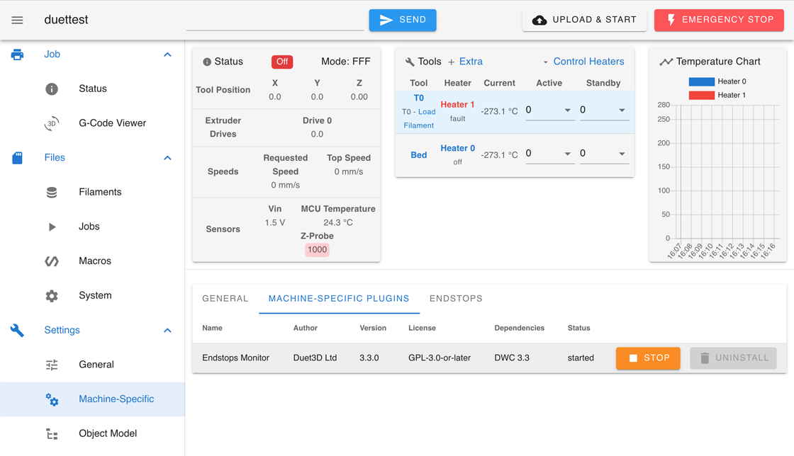
- Go to 'Settings > Plugins > External plugins' ('Settings > Machine-specific > Machine-specific plugins' in older versions of DWC) and click 'Install plugin'.
- Navigate to the "EndstopsMonitor-X.X.zip" you downloaded, select and click 'Open'.
- Click through the next few windows, reading the information and warnings.
- Once installed, click on 'Start'.
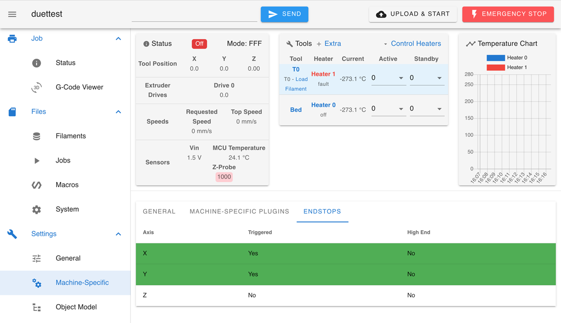
- You can now see the endstop status in 'Settings > Machine-specific > Endstops'.
¶ 9. Re-configure Endstops
If you found that any endstops are not configured properly in the last step, navigate to 'Files > System' and open the config.g file. Endstops are configured here. In RRF 3.x, each endstop has it's own configuration line, using M574, e.g.
; Endstops
M574 X2 S1 P"io1.in"  ; configure switch-type (e.g. microswitch) endstop for high end on X via pin io1.in
M574 Y1 S1 P"io2.in"  ; configure switch-type (e.g. microswitch) endstop for low end on Y via pin io2.in
M574 Z2 S1 P"!io4.in" ; configure switch-type (e.g. microswitch) endstop for high end on Z via pin !io4.in
High end or low end?
- In RRF 3.x, the M574 X, Y, and Z parameters configure the position of the endstop; 0 for no endstop, 1 for low end endstop, 2 for high end endstop. eg
M574 X0would mean no endstop on X,M574 Y2means Y endstop on the high end. - Think of "low end" and "high end" as a numeric scale for the axis. If your Y axis has a 250mm range of motion, the low end is 0mm and the high end is 250mm.
- Observe the physical location of each endstop and compare it to this setting. If it is incorrect, change it now.
- On a Delta, all endstops are usually at the high end. On Cartesian and CoreXY, the Z low end is where the nozzle is closest to the bed, ie where Z=0.
- The S parameter configures the type of endstop: 1=switch, 2=Z-probe, 3=motor stall, 4=multiple motor stall (see M574 for usage).
Note that if you changed which end your endstop is located, you will generally need to update your homing macros (homeall.g, homex.g, homey.g, homez.g and any others if you have more axes) to get the axis to move in the correct direction, towards the endstop, during homing.
Active high or active low?
- In RRF 3.x, the M574 P parameter configures the pins the endstop is connected to. It also configures how the signal is interpreted.
- An active low endstop is one which pulls the signal to ground when the endstop is pressed. On Duet, this means that it is 'normally open' (or NO) when not pressed.
- An active high endstop is one which pulls the signal to ground when the endstop is not pressed. On Duet, this means it is 'normally closed' (or NC) when not pressed. Duet3D recommend NC endstops, as they are less susceptible to interference from other sources, eg stepper motor wiring.
- On Duet 2 WiFi/Ethernet, you can test whether your endstops are active low or active high by observing the red LED next to the corresponding stepper motor connector. If the LED is lit when the endstop is triggered, this would indicate an active low endstop. If the LED is lit when the endstop is not triggered, this would indicate an active high endstop.
- If you found that the endstop was responding the wrong way in the test in the previous section, the pin input can be inverted in the endstop definition in config.g. Do this by:
- Invert the signal in the M574 command with
!, egM574 Y2 P"!ystop" - If the M574 command already has a
!in it, remove it. - If you edit config.g, any changes will be implemented when you reset the Duet.
- Alternatively, you can send the command in the GCode console, where it will have immediate effect.
- Invert the signal in the M574 command with
After confirming the operation of the endstops and to save and implement the changes you have made, you need to reset the Duet. If you edit then save the config.g, DWC should ask if you want to reset the Duet or re-run config.g. You can also press the "Reset" button on the Duet, or send
M999, or re-run config.g by sendingM98 P"config.g"in 'Control > Console'.
Further reading
See Configuring endstop switches for more details.
¶ 10. Check Stepper Motors
 Check the operation of your X, Y, Z and other axes stepper motors.
- To conduct this step, temporarily allow axis movement without homing:
- Navigate to 'Control > Console' and enter
M564 S0 H0. You can also enter GCodes into the field in the centre of the bar at the top of the page. - Navigate back to 'Control > Dashboard'.
- Navigate to 'Control > Console' and enter
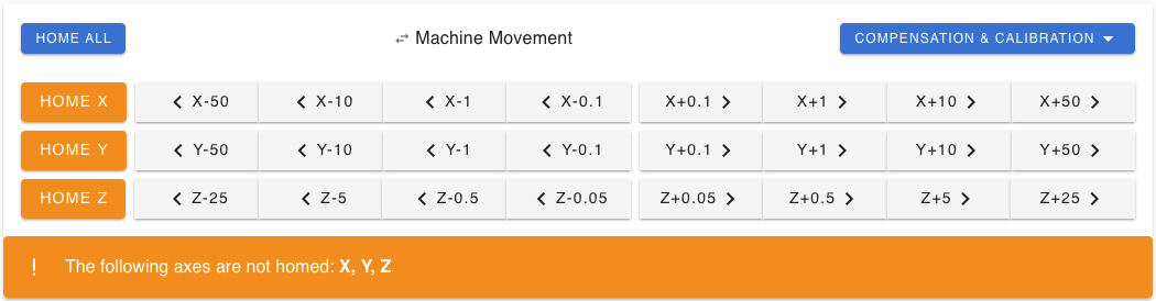
- Using the Machine Movement panel, move each stepper motor, individually, 1 mm in each direction by pressing the '< #-1' and '#+1 >' buttons for each axis, where # is the axis.
- If any motors move in the wrong direction, we will fix them after checking the extruder motors.
- Note: for cartesian kinematics, where only one motor moves for each X, Y and Z axis, this is straightforward. If you have a CoreXY, delta or Scara, see User manual: Testing stepper motors for the correct motor movements.
- Note: a stepper can't be moved before homing, unless the M564 command is used to override this safety default.
 Check the operation of your extruder stepper motors.
- To conduct this step, temporarily allow extruder movement without heating:
- Navigate to 'Control > Console' and enter
M302 P1. You can also enter GCodes into the field in the centre of the bar at the top of the page. - Navigate back to 'Control > Dashboard'.
- Navigate to 'Control > Console' and enter
- Check that the tool you are testing is active; in the Tools + Extra panel, the tool should be highlighted blue, and the heater should be active. Make sure temperatures are set to 0 to avoid heating up the hot end.
- Ideally, test the extruder motor without filament loaded, and observe the extruder gears to check which way they are turning. If you can't see them, start with no filament loaded, place some filament in the extruder so it just catches on the extruder gears, then command a short extrusion, to test which way the filament is pushed.
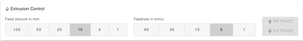
- Use the Extrusion Control panel to move the extruder motor. Select a small feed amount, eg 5mm, and slow feedrate, eg 1mm/s, and press the Retract and Extrude buttons to test which way the extruder moves.
- If the extruder motor moves in the wrong direction, we will fix it in the next step.
- If the Retract and Extrude buttons are greyed out, check that the tool is selected and active, that the M302 command has been sent. If it is still greyed out, check in config.g that your tool definition (M563) includes the extruder drive (D parameter), eg M563 P0 D0 H1 F0.
- Finish by re-applying cold extrusion prevention, with
M302 P0.
Reversing a Stepper Motor
- To reverse the direction of a stepper motor, navigate to 'Files > System' and open the config.g file.
- Look for M569 settings. S1 configures a drive to move in the "forward" direction and S0 is "reverse".
- For any stepper motors that are moving in the wrong direction, change the configuration of S1 to S0 for the corresponding drive.
After confirming the operation of the motors and to save and implement the changes you have made, you need to reset the Duet. If you edit then save the config.g, DWC should ask if you want to reset the Duet or re-run config.g. You can also press the "Reset" button on the Duet, or send
M999, or re-run config.g by sendingM98 P"config.g"in 'Control > Console'.
Check distance moved
Once the motors are moving in the correct direction, you can test if they are configured to move the correct distance.
The distance an axis moves is defined by:
- the number of steps your stepper motors takes to make a full rotation (which is set physically by the stepper motors type) multiplied by the microstepping (set by M350,
- and the number of steps per mm to move the axis (set by M92)
These should have been set correctly during Configuring firmware.
Test the X, Y, Z and any other axis motor by moving each axis a bit further (+/-10mm, then +/-100mm) and measure the distance moved with a ruler. If an axis moves too far, or not far enough, check the values you set for microstepping (M350) and steps per mm (M92).
Testing and calibrating extruder motors is covered in the next guide, Calibration
Test homing
Once you have checked your motors are moving the correct direction and distance, you can test homing.
- NOTE: if you have configured to use the Z-probe for homing, DO NOT home the Z axis yet! See the next step.
- Be sure that you have confirmed the correct operation of your endstops before homing.
- Test homing for each axis by clicking the 'HOME' button for each axis.
- If they all home correctly, test 'HOME ALL' too.
¶ 11. Z Probe
Check configuration
- Begin by familiarizing yourself with the different probe modes; see User manual: Connecting a Z probe
- Navigate to 'Files > System' and open the config.g file.
- M558 configures the Z probe. Check the P value matches whichever probe you are using.
- H value defines the dive height, which is the height above the trigger height from which probing starts.
- F value defines the "feed rate", or probing speed in millimeters per minute.
- T value defines the travel speed at which the probe is moved between probe points in millimeters per minute.
- For more information on Z probing see:
User manual: Choosing a Z probe
Connecting a Z probe
Test Z Probe
- Test the Z probe by ensuring that the status changes in Duet Web Control. e.g. If using an IR probe, by putting a piece of paper under the probe.
- For more detailed instructions, see User manual: Test and calibrate a Z probe
- Once configured, tested and calibrated, you can test homing Z.
¶ 12. Configuring PanelDue
- If you are using a PanelDue, if connected properly it should already be configured.
- You can check that it is functioning by making sure that it turned on and is displaying reasonably correct temperature information. You may also choose to home an axis or by starting a heater.
- If the display continuously shows 'connecting...' in the top right corner, make sure you have the following command in config.g:
M575 P1 S1 B57600 - You may need to update the PanelDue firmware to match the version of RepRapFirmware you are using. See Updating PanelDue firmware.
¶ 13. Commissioning Complete!
Congratulations! Upon completion of this guide, your Duet is set up.
The next step will be calibrating and tuning the various parts of your printer, running test prints, and then printing! This can include:
- Levelling the bed.
- Calibrating extruder steps per mm.
- Tuning Acceleration, Jerk, Retraction, Pressure Advance
- Input shaping
For the above see User manual: Tuning
For further details the following wiki pages are a good place to start: