¶ Introduction
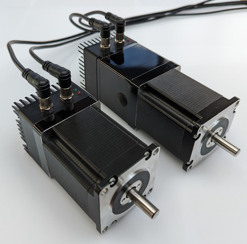
The Duet 3 Motor 23CL (M23CL) is a family of closed loop, CAN-FD connected NEMA 23 motors, fully integrated in to the Duet 3 ecosystem. They optionally integrate a brake to hold the motor in position when power is off. Connection to the Duet 3 CAN-FD bus and power use industrial M8 connectors. Multiple M23CLs can be connected to the bus, either via an M8 T splitter or a distribution board/box.
Note the M23CL series are in active development and this documentation will be expanded as we confirm specifics of each motor variant, along with bus distribution options.
¶ Features
¶ Hardware specification
| M23CL-56-2804B | M23CL-56-2804 | M23CL-76-2804B | M23CL-76-2804 | |
|---|---|---|---|---|
| Holding torque | 12.6 Kg/cm | 18.9 Kg/cm | ||
| Detent torque | 0.4 Kg/cm | 0.86 Kg/cm | ||
| Full step angle1 | 1.8deg | |||
| Max current/phase | 2.8A | 2.8A | ||
| Resistance/phase | 1.13 ohms | 0.9 ohms | ||
| Inductance/phase | 3.6 mH | 2.5 mH | ||
| Rotor inertia | 0.3Kg/cm^2 | 0.48Kg/cm^2 | ||
| Motor section length | 56mm | 76mm | ||
| Total length | 157±1mm | 107±1mm | 177±1mm | 127±1mm |
| Brake | 24V, 1.5Nm | No Brake fitted | 24V, 1.5Nm | No Brake fitted |
| Ambient temperature | -20°C to +50°C | |||
| Max motor & controller temperature | 85°C | |||
| Input voltage | 24V to 48V | |||
| Processor | Microchip ATSAME51G19A | |||
| Processor features | 32-bit, 120MHz ARM Cortex-M4F, 512Kb flash, 192Kb RAM, hardware single precision floating point unit | |||
| Networking/comms | CAN-FD bus for connection to the Duet 3 Mainboard. Optional on-board CAN-FD bus termination. | |||
| On-board stepper driver | 1x TMC2160A | |||
| Stepper driver features | SPI controlled, can be run in open loop, assisted open loop, or closed loop mode. | |||
| Encoder inputs | Hall effect, 14-bit resolution | |||
| Temperature monitoring | 1x on-board thermistor and processor temperature available for temperature monitoring. | |||
| Closed loop control monitoring | Real-time performance of the closed loop control data is available for local action or remote monitoring | |||
1 In open loop mode up to 256 microstepping can be configured
¶ Firmware notes
- See 'Firmware' section below
¶ Physical properties
¶ Dimensions


¶ 3D model
The STEP files are available from Github here
¶ Wiring
¶ Connection Diagram
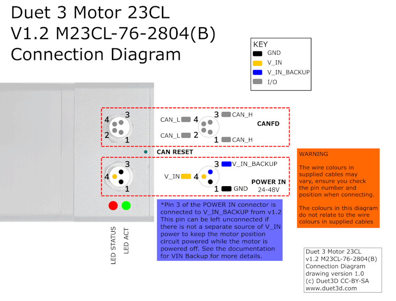
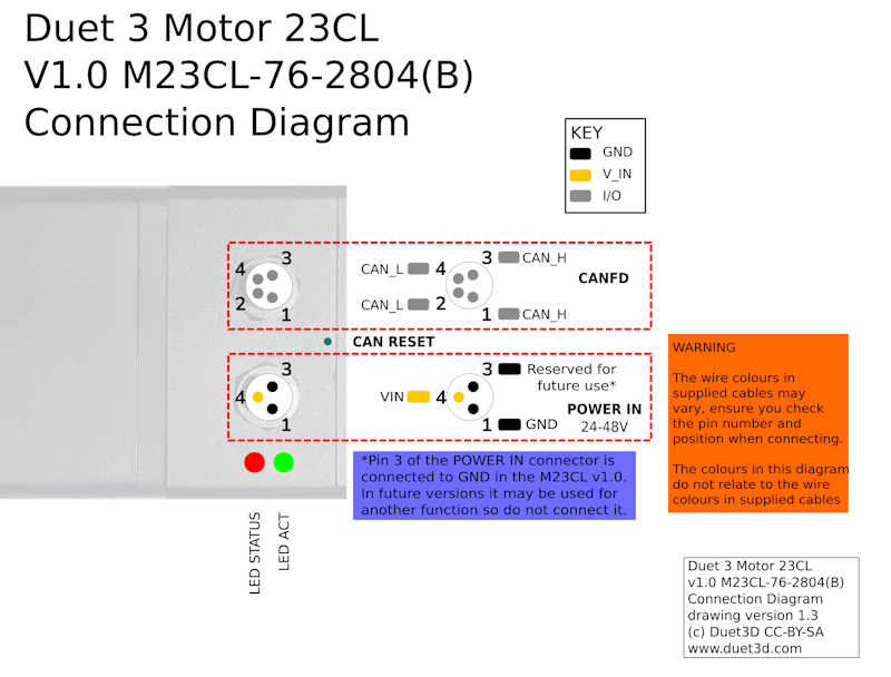
Note: Pin 3 of the POWER in connector in version v1.0 of the Duet 3 Motor23CL is internally connected GND, in later versions it is used for V_IN BACKUP so its recommended to not connect it in v1.0.
¶ Power wiring
Supply between 24V and 48V to the M8 3-way power connector on the motor, observing the correct polarity.
Do not plug or in the the motors to a power supply that is already plugged in, the inrush current can blow the internal proteciton fuse.
If you use a relay to control VIN power to the motor, ie the power supply is already switched on, and a relay is used to turn on power to the motor, you should use an inrush current limiter wired in series with VIN. See the section on Inrush current here.
OUT ports on the mainboard should NOT be used to switch power to expansion boards, tool boards or CAN-connected motors directly. See the note at the end of the 'inrush current' section at the link above.
¶ VIN Backup
Pin 3 of the POWER in connector in version v1.0 of the Duet 3 Motor23CL is internally connected GND. From v1.1 it is connected to a separately fused V_IN_BACKUP circuit that just keeps the logic elements of the control board running, but not motor power, if V_IN power is removed. this allows a safety system to interrupt motor power, without the motor loosing encoder position.
When VIN power to the motor is reapplied by the safety relay an inrush of current will occur, you should use an inrush current limiter wired in series with VIN. See the section on Inrush current here.
In version 3.6 firmware when V_IN power is applied, the motor will attempt to move back to the position its commanded to be in as rapidly as it can. If the motor was moved while VIN power was not applied then this can cause undesirable results. This behaviour may be addressed in future firmware versions, until that time avoid moving the motor when in this state, alternatively if that's not possible (e.g. due to a Z axis that moves under load when not powered), use a Motor 23CL with a brake.
¶ CAN wiring
The M23CL has two pairs of CAN_L and CAN_H connectors on a M8 4-way connector, one each for the incoming and outgoing signal. To connect it to the CAN bus, you can:
-
daisy chain the M23CL between other M23CLs, expansion or tool boards on the CAN bus. Connect the 'incoming' CAN cable to one CAN_L/CAN_H pair, and connect the outgoing CAN_L/CAN_H pair to the incoming pair of the next M23CL, expansion or tool board.
-
have the M23CL as the last (or only) device on the CAN bus. The M23CL is supplied without CAN termination, so is easiest to use between other boards. If the M23CL is the last device on the CAN bus, we recommend using external termination. Connect a 120 ohm resistor between the pins on the 'outgoing' wire pair, between CAN_H and CAN_L.
- use a Duet 3 Tool Distribution board, and wire each M23CL to the distribution board with four wires. CAN Bus termination can then be done on the Tool Distribution board.
CAN bus connections between a M23CL and other M23CLs, expansion or tool boards can be made using standard M8 cables and T splitters.
- M8 cables are widely available. Generally, you can use 4-wire M8 cables. What kind you need will depend largely on your application.
- T splitters (not Y splitters, they tend to have the wrong connections) with 4 positions on all connectors such as this one from TE Connectivity (widely available from Mouser/Digikey/RS/Farnell etc) should work. Plugging in with the middle connector of the T may obstruct the M23CL power connector, so either use the other female connector of the T, or have a short jumper cable between the T and the M23CL.
¶ Encoders
¶ Built in encoder
The M23CL incorporates a hall effect position sensor sensing a magnet on the motor shaft. The motor and the encoder need to be calibrated together as part of commissioning, see the section on doing this below.
¶ Operating Modes
The Duet3 Motor23CL supports the following modes of motor control:
¶ Open loop mode
In this mode the driver behaves in a similar way to the drivers on the 6HC main board. If an encoder has been connected and calibrated then it is possible to collect data on the position error for short periods.
¶ Closed loop mode
In this mode an error signal is computed from the difference between the desired motor position and the position reported by the encoder. This error signal is used to apply a torque to correct the error via a modified PID controller. Warning and error events can be generated when the error exceeds configurable thresholds. When the controller is unable to achieve the desired position, it will recover to the correct position when either the obstruction is removed or a command is sent to move the axis or extruder to a position that can be achieved. Maximum speed is reduced compared to open loop mode. The PID controller must be tuned for best response.
¶ Assisted open loop mode
In this mode the motor is operated as if in open loop mode, but whenever it is detected that the error between desired and actual position is getting too high, the motor current is automatically increased until the error is reduced. This allows a low initial current to be used, which makes the motor quieter at standstill and low motor speeds. As with closed loop mode, warning and error events can be generated when the error exceeds configurable thresholds. However, if the position requested cannot be achieved and the error exceeds approximately 4 full motor steps, the position will not be corrected when the obstruction is removed or the motor is commanded to a position that can be reached. No further out-of-position events will be generated until the command to enter assisted open loop mode is repeated. Unlike closed loop mode, good operation can be achieved with little or no tuning.
¶ Commissioning
¶ Initial CAN settings
All boards in the system must have different CAN addresses. Duet 3 Motor 23CLs are shipped set to a default CAN address of 123. They will also revert to 123 if you use the CAN reset button (not exposed on prototypes). Therefore, if you have more than one new M23CL or other Duet3d CAN-FD connected expansion board, only one of them must be powered up and connected to the CAN bus at a time so the address can be changed from the default. So disconnect power to all but one of them (you can leave the CAN bus connected if it's easier). When you have changed the CAN address of that M23CL, you can connect the next one; and so on. See the section: Set the CAN address below for how to change the default address.
See also CAN connection basics
¶ Startup Time
It is recommended to add the following to config.g, before any commands that reference any CAN bus connected expansion boards
G4 S2 ;wait for expansion boards to start
The first time the M23CL starts up it may request firmware from the Duet3d mainboards. Ensure you have the correct version (compatible with your mainboard firmware) in the /firmware directory on the mainboard. See the Firmware section below for more details.
¶ Testing communication
Before the M23CL is connected to the CAN-FD bus, if it is powered, the STATUS (red) LED will be blinking rapidly. Once it is connected (after any initial firmware update happens), it should settle down to a ~1Hz blink rate. If there are other blink patterns displayed see the LED behaviour and error codes section of the CAN connection basics documentation
Check that you can communicate with the M23CL, by sending:
M115 B123
If that fails try pressing and holding the CAN_RST switch when powering up, release the switch and power down, then power up again. This will reset the CAN-FD bus settings to the default (address 123, bus speed 1Mbps)
¶ Update the bootloader
Duet 3 expansion boards, tool boards and motors have a bootstrap loader written to the start of flash so that they can load firmware from the main board via CAN. This bootloader may occasionally need to be updated in order to support new features. See Updating the bootloader on Duet 3 expansion and tool boards.
¶ Updating the firmware
The M23CL will be shipped with firmware loaded during production. You can check the version loaded by sending
M115 B123
(or B## where ## is the new CAN address of the board if you have changed it already)
To update the firmware get the latest version from the RepRapFirmware github.. It is highly recommended to upgrade all the firmware in your Duet 3 system together so that the versions do not get out of sync.
Send M997 B## to carry out a firmware update. The bootloader will request the Duet3Firmware_M23CL.bin from the Duet 3 main board, which needs to be in the /firmware folder.
A firmware update can also be forced manually. Press and hold the CAN_RST switch when powering up, then release the switch. The bootloader will request new firmware from the Duet 3 main board. Note that this also resets the CAN address to the default 123, so it's best if it is the only expansion board connected to the main board, to avoid CAN address conflicts.
¶ Set the CAN address
- Send command M115 B## to verify that the main board can communicate with the M23CL, where ## is the default address of 123 if it has not been changed already.
- Send command M952 B# A## where ## is the new address you want to use. Allowed CAN addresses for normal use are 1 to 119. We suggest you use addresses starting at 70 for M23CLs. So for the first M23CL, if your new CAN board was at address 123, send M952 B123 A70.
- Power the M23CL down and up again, or send M999 B123. This will cause the M23CL to restart with the new address.
- Send command M115 B70 (or whatever address you chose) to verify that you can communicate with the M23CL at its new address
- You can now power up the next M23CL and commission it in the same way, choosing a different CAN address for it. so for the second board, e.g. M952 B123 A71 and so on.
¶ Calibrating the Encoder
For more details on this please see the section on calibrating the magnetic encoder on the closed loop tuning page, it's written for the magnetic encoder on the 1HCL but the same theory applies.
The calibration procedure measures magnet offsets and attempts to corrects for this in software. Since the magnet's position is not affected by cycling the printer's power, this data is stored in non-volatile storage such that it only has to be run once. Of course, if you change or remove and reattach the M23CL internal control board, you must re-run this tuning move.
¶ Running the calibration procedure
A little more than one full rotation of the motor is performed in each direction. Unlike other tuning moves it is recommended the motor is not connected to any axis or other load for this calibration routine.
Once you are satisfied that the motor can freely make up to 1.5 rotations in either direction, run the following commands:
M17 ; this will enable all motors you can be more specific e.g. M17 X the driver you are tuning need to be enabled before tuning
M569.6 P##.# V2 ; Where P##.# is the driver address to tune
Once this has been performed successfully, the values will be written to non-volatile memory and remembered each time the power is cycled. The tuning can be re-run by simply running the M569.6 ... V2 command again, or checked by running the M569.6 ... V3 command.
The firmware will output the highest deviation of expected position vs encoder position recorded.
To follow, acceptable ranges for deviation of position
¶ Firmware
Duet 3 Motor 23CL v1.0 is supported in RRF 3.5 and later.
Duet 3 Motor 23CL v1.2 is supported in RRF 3.6 and later.
¶ Limitations
Please see the current RepRapFirmware limitations at Duet 3 firmware with CAN expansion configuration limitations.
¶ Steps/mm & Microstepping
While in closed loop mode step pulses are not sent to the stepper motor driver in the same manner as an open loop driver. However microsteps and steps/mm are used to calculate the correct amount of rotation required in closed loop mode
In order to get correct function follow this process:
- Set the step/mm and microstepping as normal for open loop mode and test the configuration in open loop mode first. (i.e. 16 microstepping with interpolation is recommended). There is a calculator built into the config tool to assist with determining the correct steps/mm for belts/leadscrews etc.
- In closed loop and assisted open loop mode, RRF will use the same full-steps/mm that the configured microstepping and steps/mm imply. No changes in M350 or M92 are required for correct functioning in closed loop mode.
¶ Summary of control
- RepRapFirmware on the main board rounds the axes endpoint to whole microsteps. (Extruder movements are kept unrounded)
- RepRapFirmware sends the move details over the CAN-FD bus, including the move length for each axis motor measured in whole microsteps. (Whole and part microsteps for extruders)
- In open loop mode and assisted open loop mode, microsteps are generated at the appropriate times.
- In closed loop mode, the motor position is calculated from the movement parameters as a floating point number of full steps.
¶ Sample configuration examples
¶ Adding a M23CL
M569.1 is used to configure the closed loop driver.
Here's a sample excerpt from a config.g file for RRF 3.5 to drive the X and Y motors from M23CLs configured at CAN addresses 70 and 71.
M569.1 P70.0 T3 E2:4 R100 I0 D0 ; Configure the M23CL at CAN address 70
M569.1 P71.0 T3 E2:4 R100 I0 D0 ; Configure the M23CL at CAN address 71
M569 P70.0 D4 S1 ; Set into closed-loop drive mode (D4) and not reversed (S1)
M569 P71.0 D4 S1 ; Set into closed-loop drive mode (D4) and not reversed (S1)
M584 X70.0 Y71.0 ; set X and Y drivers
M906 X1600 Y1600 ; set the max current to use for X and Y

; M350 and M92 are required:
M350 X16 Y16 I1 ; set steps/mm to 16 with interpolation for open loop mode operation
M92 X80 Y800 ; steps/mm for a 20 tooth gt2 pulley.
Note the initial PID values will need to be tuned to the particular motion system.
In contrast to usual drivers, the closed loop axes can have their holding current set to zero using M917, with negligible detrimental effect. Whilst a normal driver may slip if it's holding current is set to zero, a closed loop driver will notice that it has slipped an apply a current to return the drive to it's intended position. Setting a holding current of zero will also mean less current is used, so the motor runs cooler. However, a holding current can still be set using M917 if desired. That aside you must still set the maximum current per axis using M906. if you do not then the motor will not move, or will only vibrate slightly.
¶ Tuning the PID for the closed loop
See Tuning the Duet 3 Expansion 1HCL for details on tuning the M23CL. The section on PID tuning applies to both the 1HCL and the M23CL.
¶ Temperature sensor
The following code can be used in config.g to monitor the internal control board temperature.
M308 S3 P"70.temp0" Y"thermistor"
M308 S4 P"71.temp0" Y"thermistor"
These sensors would be displayed in the "extras" tab in DWC and available in the object model to query and potentially take action on for example the following could be inserted into daemon.g to check the internal temperature every second and raise the alarm if they are higher than a set value of 70C
if sensors.analog[3].lastReading >70
    echo "X MOTOR Temp Alarm: ", sensors.analog[3].lastReading
    M98 P"motorovertemp.g"
if sensors.analog[4].lastReading >70
    echo "Y MOTOR Temp Alarm: ", sensors.analog[4].lastReading
    M98 P"motorovertemp.g"
G4 P1000
Where the "motorovertemp.g" macro can have whatever actions are appropriate. This logic can be extended to take different actions at different temperatures ( e.g. log at 60, sound alarm at 70, pause print at 80)
¶ Motor Brake Control
Some versions of the M23CL have a motor holding brake solenoid fitted (all prototypes, and model numbers ending in "B")
If a brake is present the M23CL will disable it when the motors are enabled (M17 and enable it when the motors are disabled (M18).
¶ Motor Brake Voltage
It is possible to use a V_IN voltage higher than 24V to be used with the 24V brake fitted on some models.
The motor brake circuit is a fast brake control circuit designed to allow the brake to be engaged very quickly by dumping the energy in the current flowing in the brake solenoid coil. In addition it has a PWM control circuit that will limit the current in the brake coil if the sensed V_IN voltage is above 24V.
¶ Revisions
- Change the main V_IN fuse to be replaceable (0157002.DRT)
- Change the V_IN_BACKUP fuse to be a polyfuse (160mA)
- Changed Pin3 of power connector to V_IN_BACKUP
- V_IN_BACKUP fused with the same fuse as V_IN
- Changed to 76mm motor as the first production model
- All other specifications set as per the details above.
- The initial M23CL with a 56mm motor body, brake and an 8mm shaft.