¶ Introduction
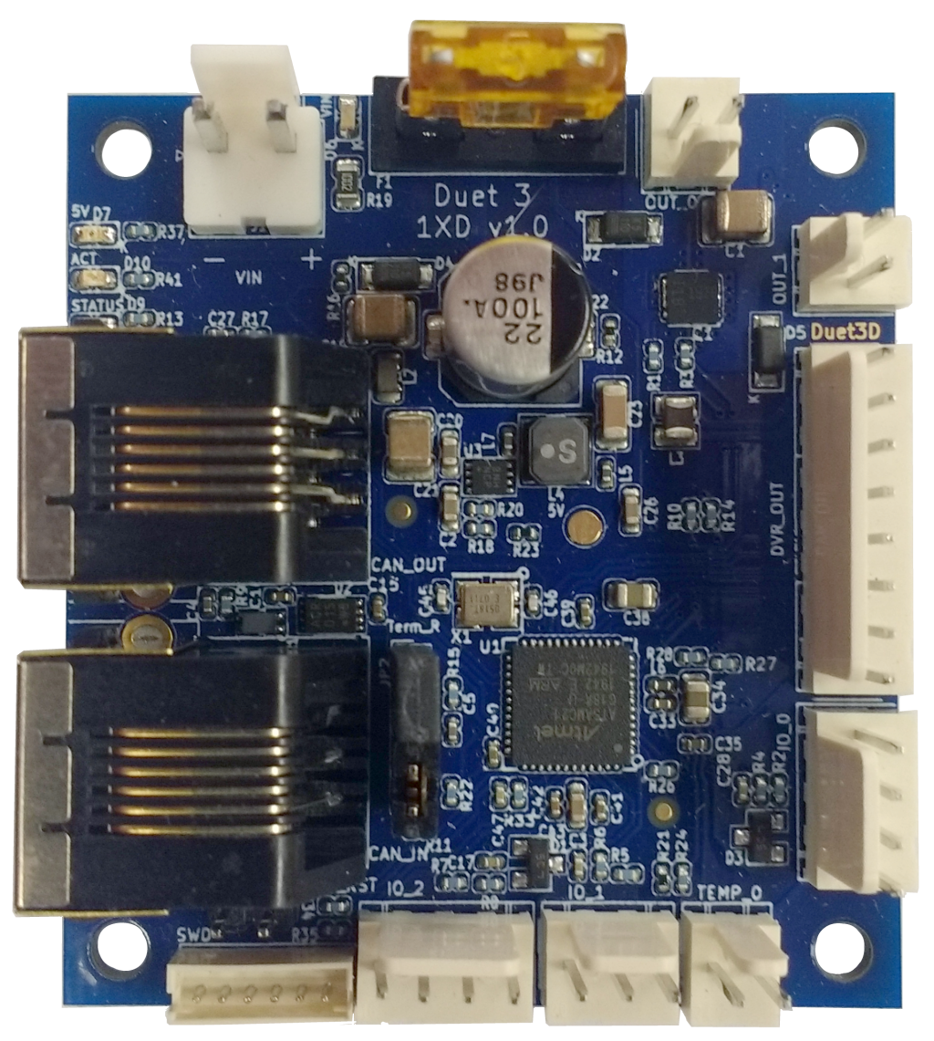
The Duet 3 Expansion 1XD board provides step, direction and enable outputs to interface a Duet 3 system with a motor controller that takes those inputs. In addition it has a number of peripheral inputs and outputs for functions such as sensing driver alarms, temperature and controlling a brake and axis endstop. It connects to the Duet 3 CAN-FD bus using RJ11 connectors (same as the Duet 3 Mainboard 6HC, Duet 3 Mini 5+, Duet 3 Expansion 3HC, and the Duet 3 Tool Distribution Board). Multiple drivers can be daisy chained on the bus, with power (up to 48V) provided locally to the Duet 3 Expansion 1XD board. This allows for very large machines to be constructed without a significant wiring burden and signal integrity issues.
¶ Features
¶ Hardware specification
| Processor | ATSAMC21G18A |
| Processor features | 32-bit, 48MHz ARM Cortex M0+, 256KB Flash, 32KB RAM |
| Networking/Comms | RJ11 CAN In and CAN Out connectors to connect to the Duet 3 CAN-FD bus; serial port |
| External stepper driver support | 1 x 5V differential Step, Dir and Enable output, plus two common +5V pin. |
| Medium current output | 2 x 2A |
| Temperature inputs | 1 x output, optimised for thermistors (reduced accuracy compared to other Duet 3 boards) |
| Inputs/Outputs | 2 x 5V PWM outputs, 3 x digital inputs. Inputs are 30V-tolerant. |
| Power monitoring | VIN voltage reporting |
¶ Operating limits
| External stepper driver output | Each pin can source/sink a max of 10mA. |
| Medium current outputs | OUT0/1 up to 2A each |
| Input power voltage | 12V to 48V |
| Power input connector rated current | 10A maximum, or fused limit (whichever is lower) |
| Inputs/Outputs | All inputs are 30V-tolerant |
| Fuses | 5A |
| 5V current limit | 300mA peak total, 50mA continuous |
| Maximum ambient temperature | 70°C |
¶ Firmware notes
- Compatible RepRapFirmware versions: RRF 3.x
- Firmware limitations: See Duet 3 with CAN expansion firmware configuration limitations.
¶ Open source
- The Duet 3 1XD is Open Hardware, see our license here.
- All hardware source files are available on Github.
- Both the Duet Web Control web interface and RepRapFirmware are Open Source Software with source files available and actively maintained, see Contributing to development for more information.
- The Duet hardware and RepRapFirmware are built with Open tools: designed in KiCad and Eclipse using open tools means the barrier to getting involved is as low as possible.
¶ Physical properties
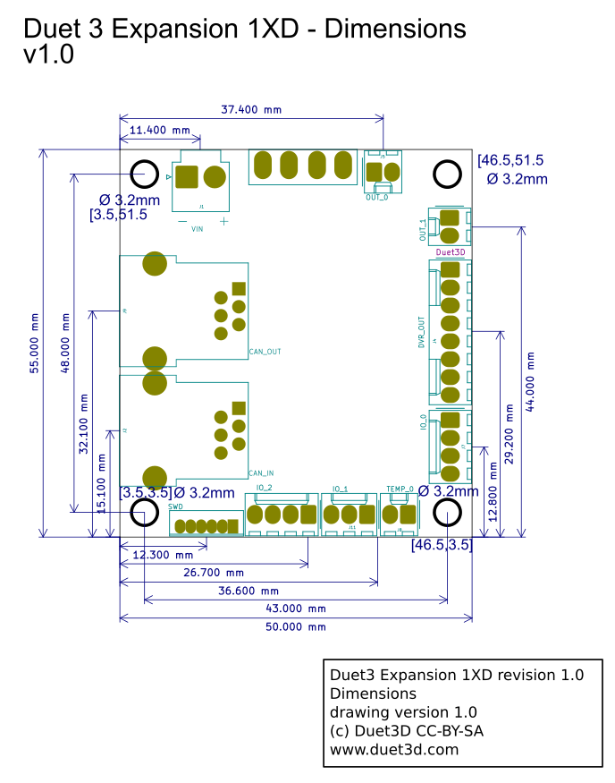
¶ Dimensions
¶ 3D model
A STEP 3D model of the Duet 3 Expansion 1XD is available on github.
¶ Step rate tests
| Step Rates Measured - RRF3.2 | ||||||
|---|---|---|---|---|---|---|
| Step Pulse Timing a (µs) | ||||||
| Motors | Move Details | "fast" b | 1 | 2.5 | 5 | 10 |
| 1 motor | "long" move (50K steps) | 83Khz | 55kHz | 48kHz | 40kHz | 30kHz |
| 3 motors | Linear Kinematics, per motor, "long" move (50K steps) | 70Khz | 51Khz | 48Khz | 40Khz | 30Khz |
| 3 Motors | Linear Kinematics, per motor, "short" moves (100x500 steps) | 41Khz | 44Khz | 40Khz | 36Khz | 27Khz |
Notes
a The requested pulse timing using M569 Tn:n:n:n . For these tests all the timings were set to the same (e.g. T5:5:5:5). Note in RRF 3.2 the exact pulse produced will be no shorter than this time but may be (slightly) longer due to clock rates and move processing times
b This is setting T0:0:0:0 this allows the firmware to generate short pulses. in measurement these where no shorter than 0.7ns.
The default step pulse timing on the Duet 3 Expansion 1XD is ~2.6µs (equivalent to the T2.5 in the table above). This is because many external stepper and servos drivers require about 2.5µs or longer pulses.
¶ Physical connections
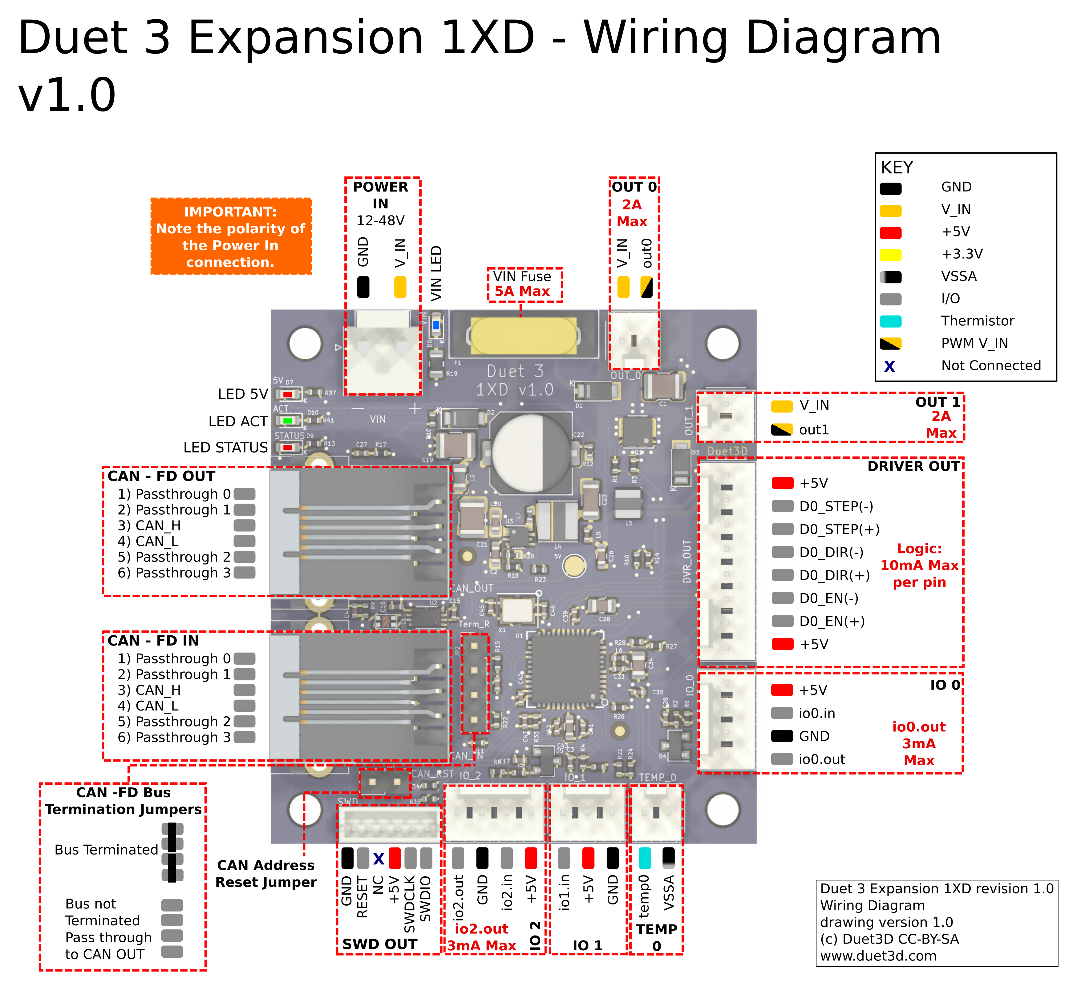
¶ Wiring diagram
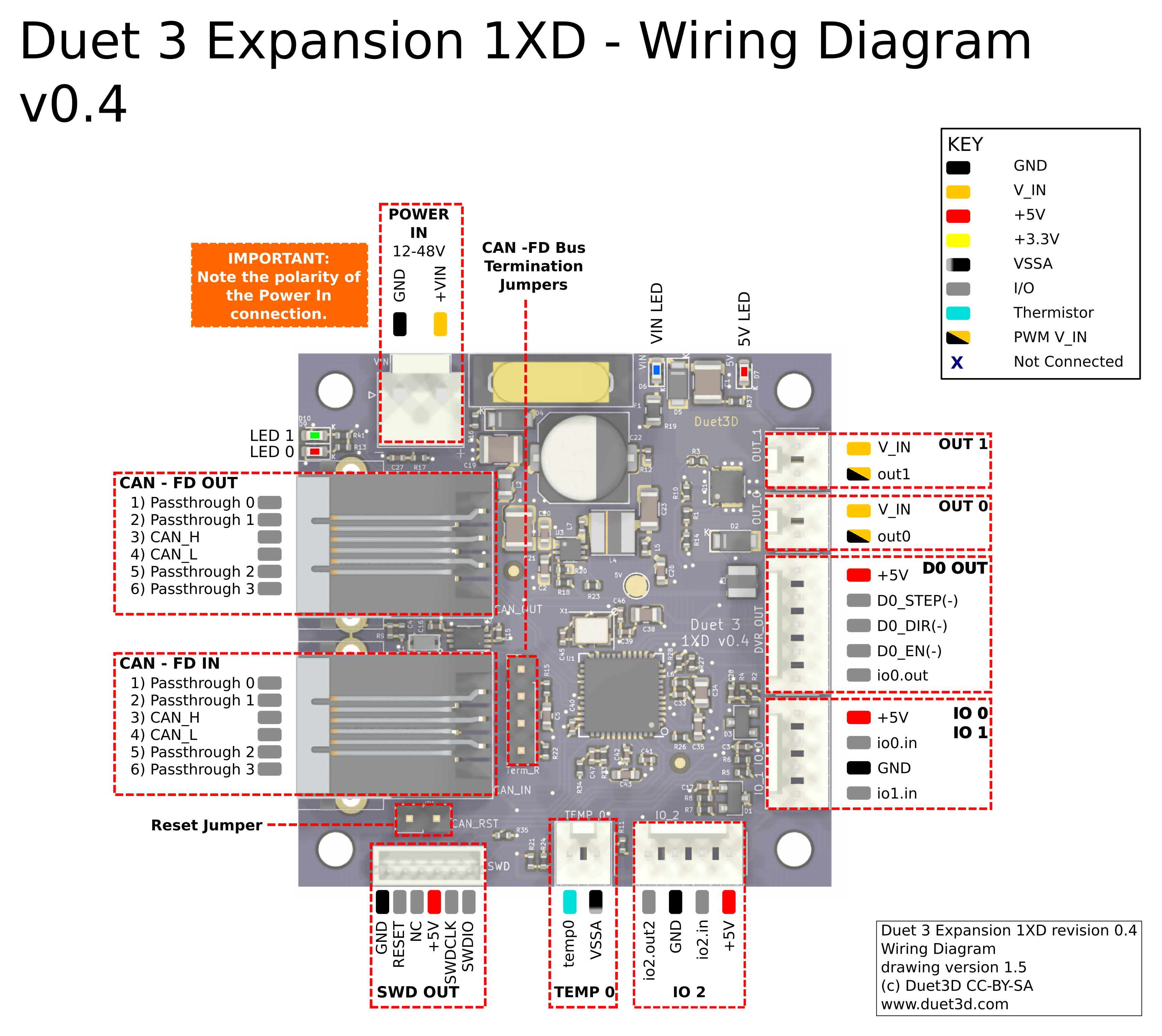
The .svg version of this diagram is available on github.
¶ Description of Connections
Duet 3 Expansion 1XD provides the following connectors:
| Header | Label | Function |
|---|---|---|
| 1 x 2-pin JST VH | POWER IN, VIN, GND | Two pins for main VIN and GND. VIN power is fused at 5A. |
| 1 x 2-pin KK header | OUT_0 | Low-current (2A max recommended) output at VIN voltage with PWM capability and built-in flyback diode |
| 1 x 2-pin KK header | OUT_1 | |
| 1 x 8-pin KK header | DVR_OUT | 5V differential Step, Dir and Enable outputs for a single external stepper driver, plus two common +5V pin. Each pin can source/sink a max of 10mA. |
| 1 x 4-pin KK header | IO_0 IO_2 | For low-voltage I/O functions. Inputs for endstops, alarm, brake release etc, output for Alarm reset signal, start built in function (eg homing). Inputs have permanent 27K pullup resistors and will tolerate up to 30V. The outputs are PWM-capable with 5V signal levels and 470R series resistors. |
| Caution! Check the pinout of these using the wiring diagram linked above before connecting anything to them. | ||
| 1 x 2-pin KK header | TEMP_0 | The "temp0" input is for thermistors but is not as high accuracy as other Duet boards. It is intended for monitoring, for example, the stepper motor temperature, not for serious temperature control. It doesn't have the auto calibration of other Duet 3 boards. |
| 1 x 3-pin KK header | IO_1 | Input only, for low-voltage functions. Inputs for endstops, alarm, brake release etc. Input has permanent 27K pullup resistor and will tolerate up to 30V |
| Caution! Check the pinout of these using the wiring diagram linked above before connecting anything to them. | ||
| 1 x 6-pin JST ZH | SWD | This is for firmware debugging and also provides a backup mechanism to program firmware. |
| 1 x 2-pin KK header | CAN_RST | Jumper to force bootloader to request firmware update from Duet 3 main board |
| 1 x 4-pin KK header | TERM_R | CAN bus terminaton. See CAN section below. |
| 2 x RJ11 CAN connectors | CAN_IN CAN_OUT | RJ11 CAN connectors. See CAN section below. |
¶ LED indications
LEDs are provided to indicate the following:
| Label | Colour | Function |
|---|---|---|
| V_FUSED | Blue | Indicates presence of fused VIN power |
| 5V | Red | Indicates presence of 5V power from on-board regulator |
| ACT | Green | Indicates activity on the CAN-FD bus |
| STATUS | Red | Status LED. See description below |
Status LED: In normal use, the red LED flashes slowly in sync with the main board to indicate that it has CAN sync, or flashes continuously and rapidly to indicate that it doesn't. It also flashes startup error codes, for example if the bootloader doesn't find valid firmware on the board. For a list of these error codes see CAN_connection basics.
¶ Pin names
For more information on pin names, see Pin Names.
RepRapFirmware 3 uses pin names for user-accessible pins, rather than pin numbers, to communicate with individual pins on the PCB. In RRF 3 no user-accessible pins are defined at startup by default. Pins can be defined for use by a number of gcode commands, eg M574, M558, M950.
The Duet 3 series uses the pin name format "expansion-board-address.pin-name" to identify pins on expansion boards, where expansion-board-address is the numeric CAN address of the board. A pin name that does not start with a sequence of decimal digits followed by a period, or that starts with "0." refers to a pin on the Duet 3 Mainboard.
| Pin location | RRF3 Pin name | Notes |
|---|---|---|
| Outputs | ||
| OUT_0 | out0 | 2A max output |
| OUT_1 | out1 | 2A max output |
| Inputs/Outputs | ||
| IO_0 | io0.in | 30V tolerant |
| io0.out | 3mA max | |
| IO_1 | io1.in | 30V tolerant |
| IO_2 | io2.in | 30V tolerant |
| io2.out | v1.0 and later board. 3mA max | |
| TEMP_0 | temp0 | |
¶ Input/Output
OUT_0 and OUT_1 are PWM-capable, maximum current 2A.
The individual IO_x connectors have the following capabilities:
| IO # | UART/I2C? | Analog in? | PWM out? | Notes |
|---|---|---|---|---|
| 0 | No | No | Yes | |
| 1 | No | Yes | No | Input only, no ouput pin. |
| 2 | No | No | Yes |
Note: RepRapFirmware does not currently support I2C on Duet 3 boards.
¶ Power wiring
Supply between 12V and 48V to the 2-pin JST VH VIN power connector on the board, observing the correct polarity.
If you use a relay to control VIN power to the board, ie the power supply is already switched on, and a relay is used to turn on power to the board, you should use an inrush current limiter wired in series with VIN. See the section on Inrush current here.
OUT ports on the mainboard should NOT be used to switch power to expansion or tool boards directly. See the note at the end of the 'inrush current' section at the link above.
¶ External Stepper Connection
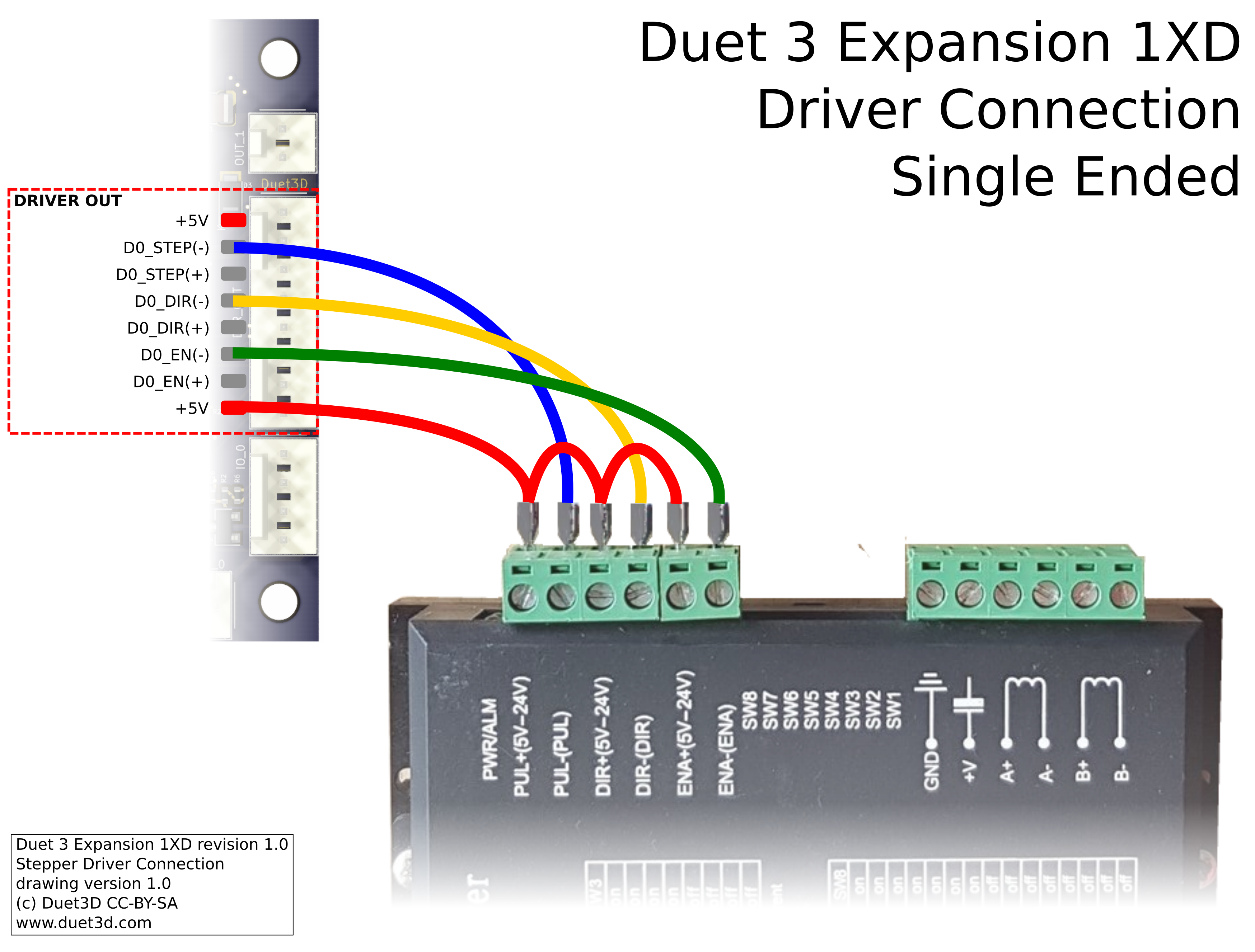
The Duet 3 Expansion 1XD v1.0 offers two methods of connecting to external stepper and servo drivers that accept a 5V step/dir/enable signal. Many drivers will work fine in single ended mode, which requires less wiring. Differential mode should be more resistant to electrical noise. Some drivers will only work with differential mode.
In this mode the +5V wire from the 5-pin connector on the Duet 3 Expansion 1XD is daisy chained to Step+, Dir+ and Enable+ on the external driver.
| Duet 3 Expansion 1XD Pin | Driver Pin |
|---|---|
| D0_STEP(-) | STEP-* |
| D0_DIR(-) | DIR- |
| D0_EN(-) | EN- |
*Note on some drivers the Step pin is called the Pulse or PUL pin.
¶ CAN
See also CAN connection basics.
¶ Connection
Two RJ11 connectors labeled CAN IN and CAN OUT. In fact it doesn't matter which you use for the cable from the main board and which you use for the cable to the next expansion board, because they are wired in parallel.
The STATUS LED indicates CAN bus state. When the expansion board starts up this LED will blink rapidly. If the expansion board is connected to a main board running compatible firmware, the LED on the expansion board will switch to blinking synchronously with the main board LED once time sync has been established across the CAN bus.
¶ Termination
Just behind the RJ11 connectors is a 4-pin terminal block. On the last board in the CAN chain only (the one with a cable in only one of the RJ11 connectors), two jumpers must be fitted in that block to terminate the CAN bus. Jumpers must not be fitted in expansion boards that are not at the end of the CAN bus.
¶ Address
See "Set the CAN address" below.
¶ Commissioning
See also CAN connection basics.
¶ Default configuration
All boards in the system must have different CAN addresses. Duet 3 Expansion 1XD boards are shipped set to a default CAN address of 122. They will also revert to 122 if you use the jumper to force the bootloader to request new firmware. Therefore, if you have more than one new Duet 3 Expansion 1XD board, only one of them must be powered up and connected to the CAN bus. So disconnect power to all but one of them (you can leave the CAN bus connected if it's easier). When you have changed the CAN address of that board, you can connect the next one; and so on.
¶ Startup Time
It is recommended to add the following to config.g, before any commands that reference any CAN bus connected expansion boards
G4 S2 ; wait for expansion boards to start
¶ Testing communication
Check that you can communicate with the Duet 3 Expansion 1XD board, by sending:
M115 B122
If that fails try placing a jumper on the CAN_RST pins and powering up, then power down and remove the jumper before powering up again, this will reset the CAN-FD bus settings to the default (address 122, bus speed 1Mbps)
¶ Update the bootloader
Duet 3 expansion boards and tool boards have a bootstrap loader written to the start of flash so that they can load firmware from the main board via CAN. This bootloader may occasionally need to be updated in order to support new features. See Updating the bootloader on Duet 3 expansion and tool boards.
¶ Updating the firmware
The Duet 3 Expansion 1XD board will be shipped with firmware loaded during production. You can check the version loaded by sending
M115 B122
(or B## where ## is the new CAN address of the board if you have changed it already)
To update the firmware get the latest version from the RepRapFirmware github. It is recommended to upgrade all the firmware in your Duet 3 system together so that the versions do not get out of sync.
Send M997 B## to carry out a firmware update, the bootloader will request the Duet3Firmware_EXP1XD.bin from the Duet 3 Mainboard, it needs to be in the /firmware folder (/sys folder for versions of RRF before 3.3).
¶ Set the CAN address
- Send command
M115 B##to verify that the main board can communicate with the 1XD board, where ## is the default address of 122 if it has not been changed already. - Send command
M952 B# A##where ## is the new address you want to use. Allowed CAN addresses for normal use are 1 to 119. We suggest you use addresses starting at 40 for 1XDs. So for the first 1XD board, if your new CAN board was at address 122, sendM952 B122 A40. - Power the system down and up again, or send
M999 B122. This will cause the 1XD board to restart with the new address. - Send command
M122 B40(or whatever address you chose) to verify that you can communicate with the 1XD board at its new address - You can now power up the next 1XD board and commission it in the same way, choosing a different CAN address for it.
¶ Configuration examples
CAUTION: before using these examples check the datasheet and user manual of the external driver you are using. Especially: check compatibility of signal voltages and the implication's of triggering actions on the external driver or motors.
The board defaults to the following external driver parameters (note, these may change in future firmware versions):
- ENA output: active to enable drive (M569Pxx R0). If driving the ENA pins of your external driver disables the drive, use R1 in the M569 command for this driver.
- 2.7us minimum step pulse width, step pulse interval, direction-to-step setup time, and direction-to-step hold time (M569 Pxx T2.7:2.7:2.7:2.7). These are satisfactory for some external stepper drivers.
Here's an sample excerpt from a config.g file to drive the X and Y motors from Duet 3 Expansion 1XD boards configured at CAN addresses 40 and 41, driving DM556 or similar drivers:
M569 P40.0 S0 R1 ; change enable polarity, active = disable drive
M569 P41.0 S0 R1 ; change enable polarity, active = disable drive
M584 X40.0 Y41.0 ; set X and Y drivers
Some closed loop drivers provide an alarm signal when they are unable to maintain the required torque/velocity or some other parameter is out of range. To use one of the io inputs to monitor this signal first configure it as a GPIO (io0.in in this example)
M950 J4 C"!^40.io0.in" ; create input pin number 4 on 1XD board at CAN address 40 for servo alarm. The alarm is active low so invert the input and enable the pullup to prevent spurious alarms caused by noise

M950 P5 C"40.io0.out" ; create a GPIO pin number 5 on 1XD board at CAN address 40 for alarm reset

M581 P4 S0 T3 R1 ; invoke trigger 3 when an active-to-inactive edge is detected on input 4 and a file is being printed from SD card
The sys/trigger3.g macro file would then contain suitable actions to undertake when the alarm signal was detected.
At the end of that trigger macro (if some method of auto-recovery was available) or driven by a user macro a sequence such as:
M42 P5 S1 ; set the alarm reset pin to logic 1
G4 P300 ; wait 0.3s
M42 P5 S0 ; set the alarm reset pin to logic 0
could be used to reset the alarm on the driver (refer to the motor driver documentation on how to reset an alarm)
The temperature sensor is less accurate than those on other Duet 3 boards designed for extruders or other heater circuits. It is most suited to using with Thermistors, not PT1000 sensors. The following code could be used in config.g to set the sensor as a thermistor:
M308 S3 P"40.temp0" Y"thermistor" T100000 B3950 A"X Motor Temp" ;Setup temp 0 on 1XD at CAN address 40 as sensor 3 - sensing X motor temperature
M308 S4 P"41.temp0" Y"thermistor" T100000 B3950 A"Y Motor Temp" ;Setup temp 0 on 1XD at CAN address 41 as sensor 4 - sensing Y motor temperature
These sensors would be displayed in the "extras" tab in DWC and available in the object model to query and potentially take action on for example the following could be inserted into daemon.g to check the motor temperature every few seconds and raise the alarm if they are higher than a set value of 70C
if sensors.analog[3].lastReading >70
  echo "X MOTOR Temp Alarm: ", sensors.analog[3].lastReading
  M98 P"motorovertemp.g"
if sensors.analog[4].lastReading >70
  echo "Y MOTOR Temp Alarm: ", sensors.analog[4].lastReading
  M98 P"motorovertemp.g"
G4 P1000
Where the "motorovertemp.g" macro can have whatever actions are appropriate. This logic can be extended to take different actions at different temperatures ( e.g. log at 70, sound alarm at 80, pause print at 100)
Some drivers have a motor brake control pin for an external holding brake solenoid. As long as the solenoid max current draw is <2A and it is rated for the VIN voltage used it can be directly controlled by out 0 or out 1. The signal to apply/remove the brake would be generated by the motor driver and connected to an IO input pin, in this example io1.in. Ensure you confirm the logic of the brake enable/disable pin, e.g. does 3.3V indicate apply or remove the brake!
The following lies would be added to config.g to setup the input and output:
M950 J6 C"40.io1.in" ; create input pin number 6 on 1XD board at CAN address 40 for brake enable.

M950 P7 C"40.out0" ; create a GPIO pin number 7 on 1XD board at CAN address 40 for the brake solenoid.

M581 P6 S1 T4 R0 ; invoke trigger 4 when an inactive to active edge is detected on input 6 (at any time).

M581 P6 S1 T5 R0 ; invoke trigger 5 when an active to inactive edge is detected on input 6 (at any time).
then /sys/trigger4.g could simply contain the code to turn on the solenoid:
M42 P7 S1 ; set board 40 out 0 to 1 (turn on brake)
with similar code in trigger5.g to turn it off.
NOTE: proceed with caution, always test these examples with low motor current and slow speeds first.
¶ Revisions
This is a minor revision with no changes to functionality or mounting hole positions
- The SWD header may not be populated.
- Additional test points added.
- 5V power indication LED moved to more easily distinguish the CAN STATUS LED (they are both red)
- Additional protection to the temperature measurement circuit
Significant changes from v0.4
- Driver 0 is now differential output rather than single ended.
- IO pins rearranged to have each IO on their own 3 or 4 pin header.
- io2.out2 is now named io2.out and is now PWM capable
- LED 0 and LED 1 are now named Status and Act respectively
- Silkscreen labels corrected
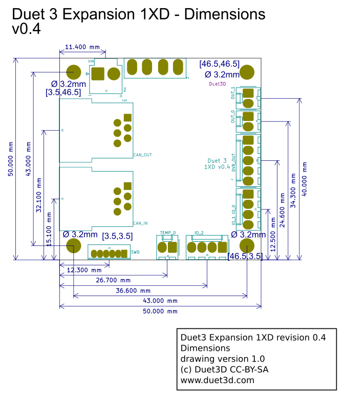
¶ v0.4 Dimensions
¶ v0.4 Wiring
¶ v0.4 Stepper connections
Here is a typical connection between the Duet 3 Expansion 1XD and an external stepper driver.
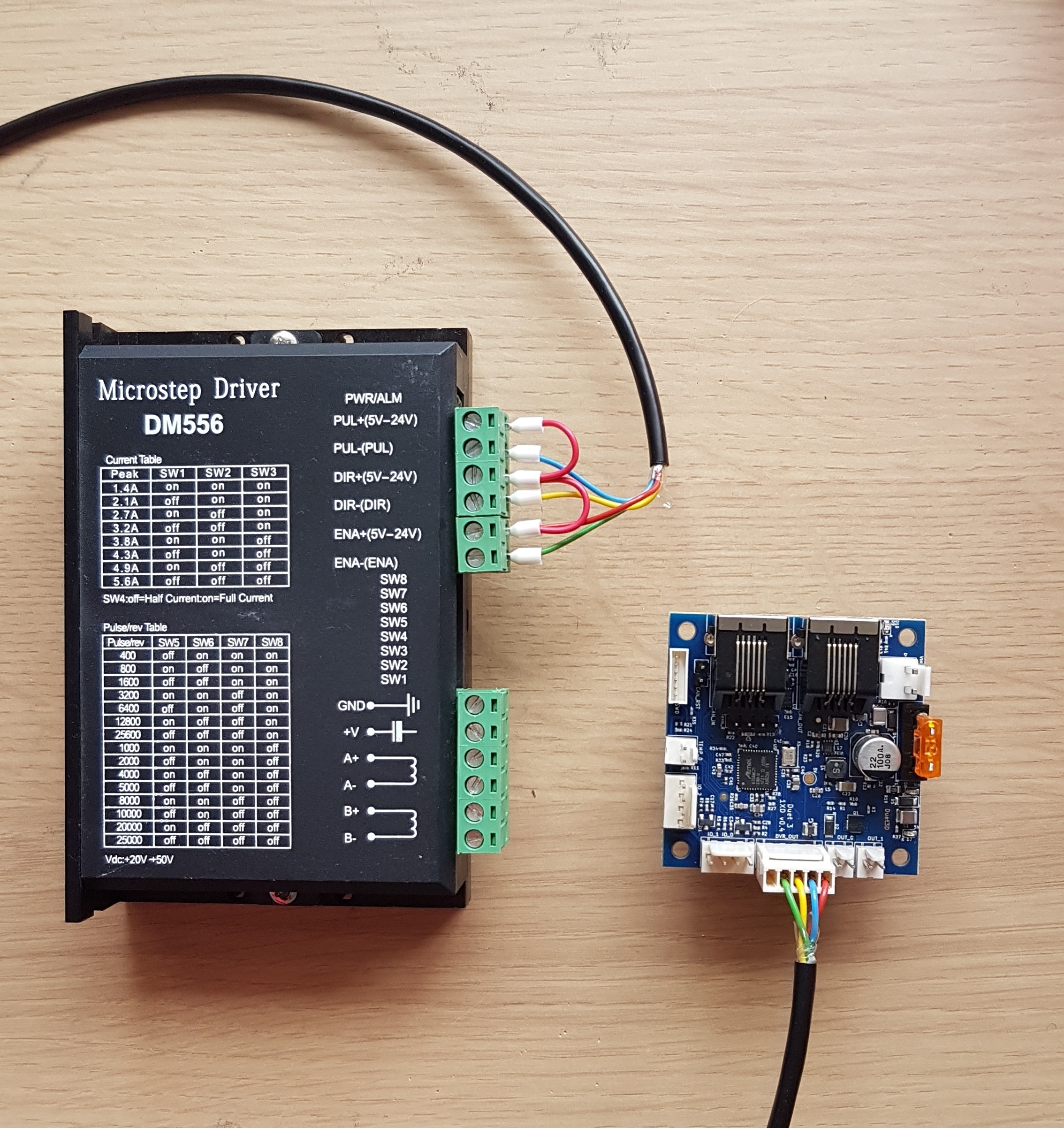
| Duet 3 Expansion 1XD Pin | Driver Pin |
|---|---|
| D0_STEP(-) | PUL-(PUL) |
| D0_DIR(-) | DIR-(DIR) |
| D0_EN(-) | EN-(EN) |
The +5V wire from the 5-pin connector on the Duet 3 Expansion 1XD is daisy chained to Step+, Dir+ and Enable+ on the external driver.
¶ Prototype v0.4 errata
The prototype boards are labelled "Duet 3 1XD v0.4". These boards have the following errata:
- The pin labelling for connector IO_0 IO_1 on the underside of the board is incorrect. The GND and IO_1_IN labels should be swapped.
- Pin IO_2_OUT is not PWM capable
- Pin IO_2_OUT must be addressed in M950 commands as "io2.out2" instead of as "io2.out"
