¶ Introduction
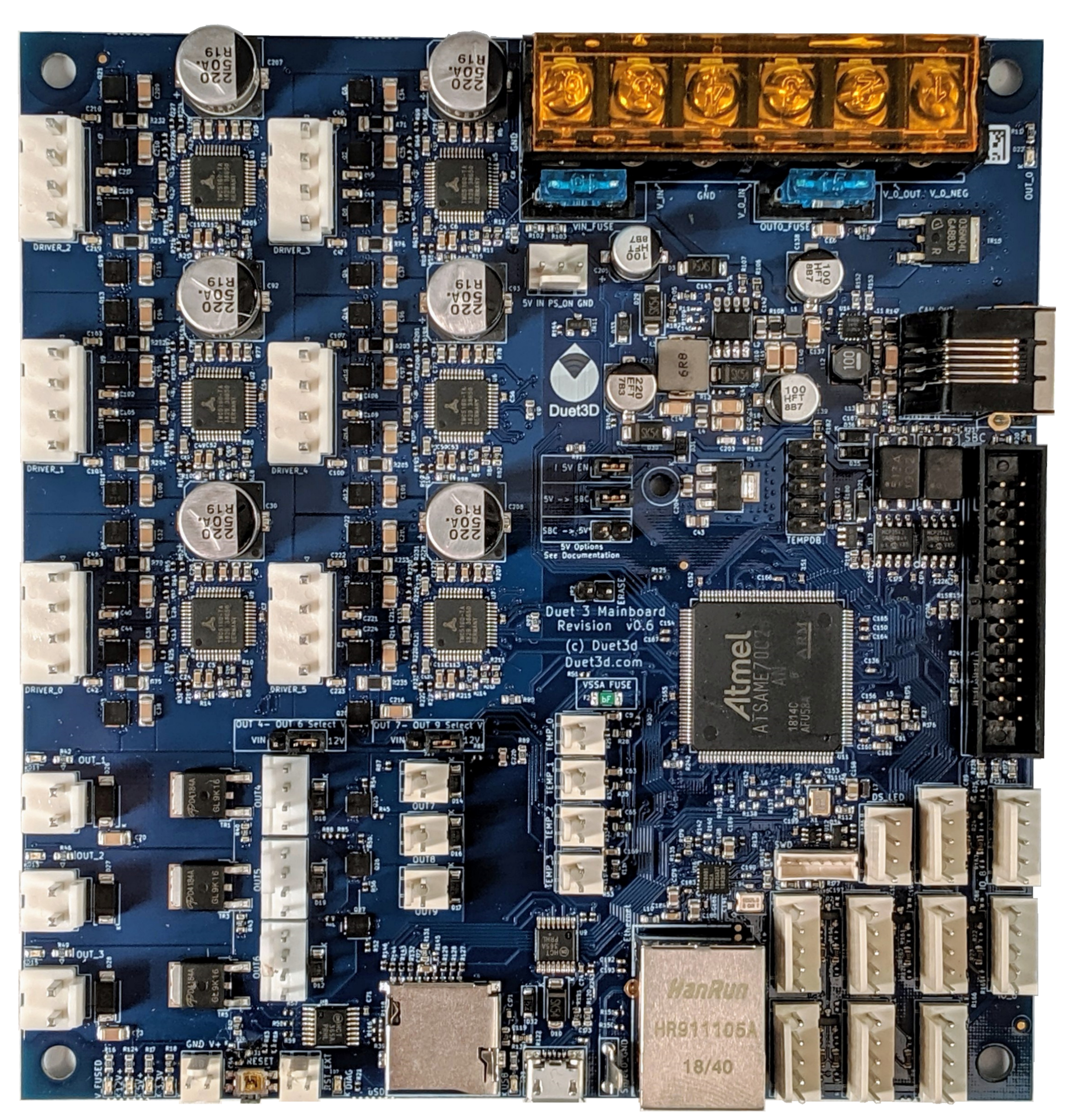
Congratulations on your new Duet 3 Mainboard 6HC! This page will guide you through getting connected, updating firmware, setting up initial configuration.
First, read the warnings! See Warnings, Fire safety and USB ground loops for precautions you must take.
¶ Package contents
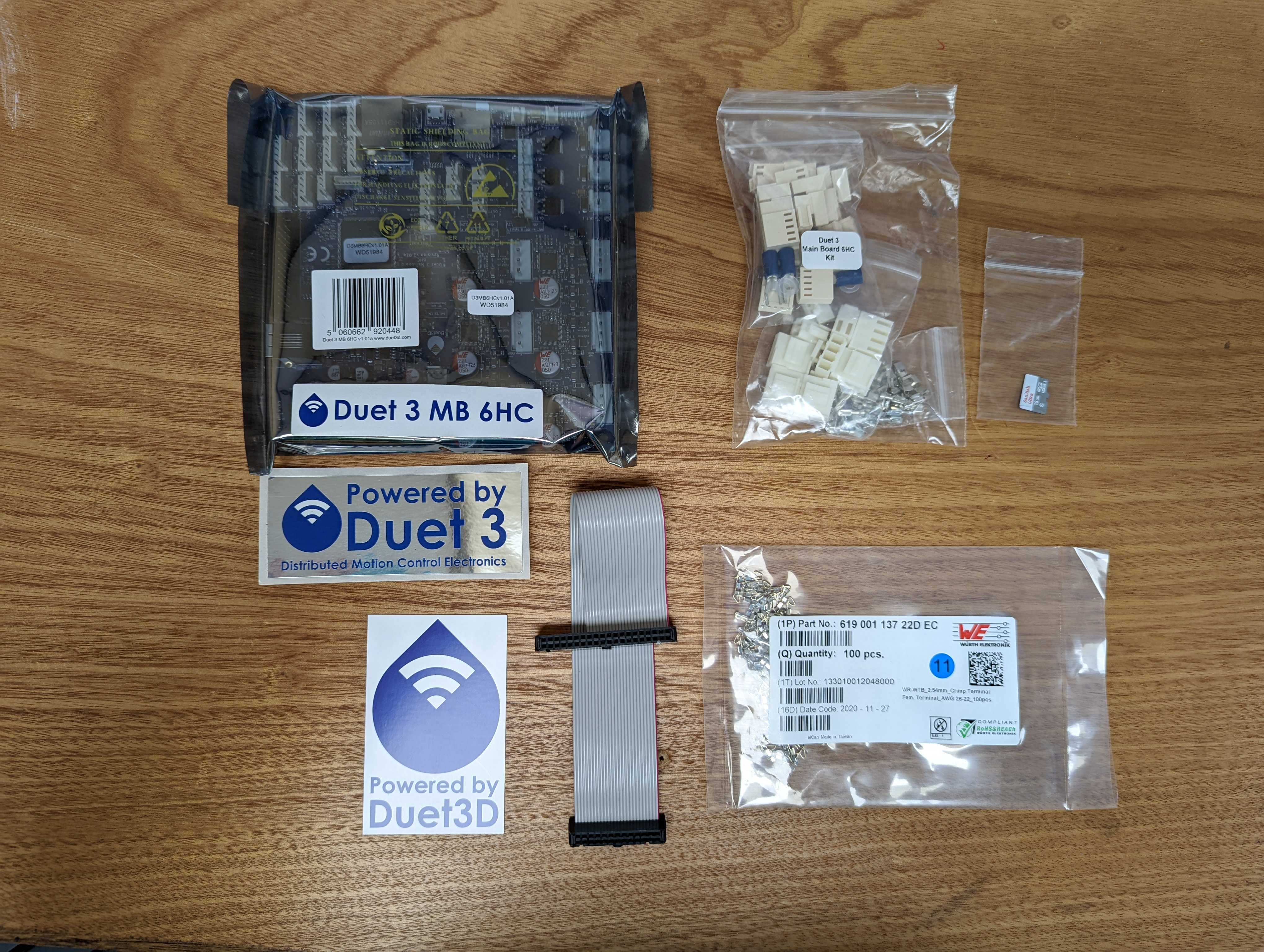
- 1 x Duet 3 Mainboard 6HC
- 1 x Connector kit, including:
- Würth Elektronic WR-WTB series connectors (Molex-KK compatible)
- Fork crimps for power input and bed heater
- JST VH connectors and crimps for stepper motors and hotend heaters.
- Plastic washers for isolation when mounting.
- 100 x crimps for connectors (Molex-KK compatible)
- 1 x micro SD Card
- 1 x 26/40 Single Board Computer (SBC) ribbon cable
¶ Standalone mode vs SBC mode
The Duet 3 Mainboard 6HC is designed to either be directly connected to a network, or to connect to a Single Board Computer (SBC) like a Raspberry Pi. All standard printer functions, different kinematics, the network UI (Duet Web Control) etc work in both modes.
SBC mode allows part of the functionality to be handled by the SBC. This offers a number of benefits:
- Faster network transfer speeds
- Support of plugins requiring more than RRF/DWC
- Usage of external HDMI or DSI screens
- Easy software and firmware update via package manager
- Optional webcam integration
- Optional HTTPS support
¶ Minimum configuration
- Duet 3 Mainboard 6HC
- Raspberry Pi or other compatible Single Board Computer (SBC). Initially this has to be Model 3B or 4 but we may support some other models in the future.
- Ribbon cable to connect the Raspberry Pi to the Duet. If using the version 0.5 Duet 3 main board, this must be 40-pin. If using a version 0.6 and later Duet main board, use 26-pin to 40-pin. Recommended length is 100 to 200mm. Longer cables will degrade the SPI signal between the Raspberry Pi and the Duet, however it may be still possible to drive them either at reduced SPI transfer speeds or with extra shielding against external EMI sources (foil wrap)
- Power supply (min. 12V. max 32V, recommended 24V) and cables
- Stepper motors, heaters, thermistors, endstop switches etc. as required
- Supplied SD card with Duet Pi image in the Raspberry Pi
- No SD card in the Duet 3
- Duet 3 Mainboard 6HC
- Power supply (min. 12V. max 32V, recommended 24V) and cables
- Stepper motors, heaters, thermistors, endstop switches etc. as required
- Supplied SD card in the Duet 3
¶ Optional extras
- Duet 3 expansion board(s) and/or tool boards
- RJ11 twisted pair cables to connect the expansion board(s). When connecting a version 0.5 Duet 3 main board to an expansion board, the wires must be crossed. When connecting a version 0.6 or later Duet 3 main board to an expansion board, or connecting two expansion boards together, the cable wiring must be straight-through. Only a single twisted pair is required, connected to pins 3 and 4 (the middle 2 pins) of the connector. Pins 2 and 6 on the version 0.6 Duet 3 main board are the connections for the secondary CAN bus, but the firmware does not use this yet.
- 2-core red/black cable to daisy chain power to the expansion board(s)
¶ Getting started
Here is a photo showing a bench setup comprising a version 0.5 Duet 3 main board, Raspberry Pi 3B+, and one early prototype Duet 3 expansion board. Caution! Note the orientation of the 40-pin ribbon cable. The connector on the Raspberry Pi is not keyed, so be very careful to connect the ribbon cable the right way round and in the correct position. Caution! Note the order of the VIN + and - terminals on the Duet 3 main board (the red wire is +ve), which is not the same as on Duet 2!
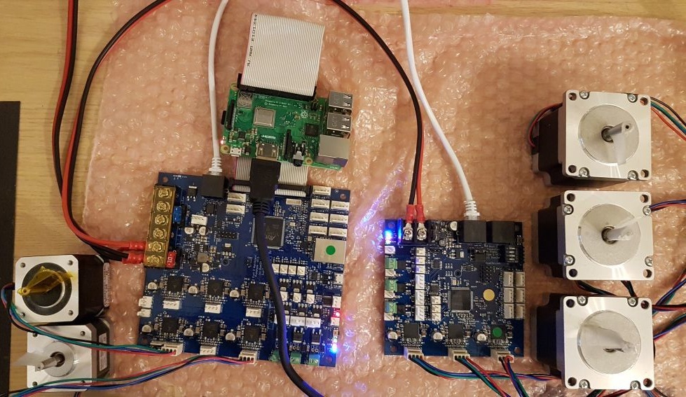
The position of the ribbon cable may appear awkward. However, our intention is that the Raspberry Pi be mounted below or above the Duet, so that the USB and Ethernet connectors on the Raspberry Pi line up with the right hand edge of the Duet. It's also possible to position the Pi on the opposite side of the Duet and run the ribbon cable underneath the Duet, but this requires a 200mm long cable.
On the version 1.0 and 0.6 board, jumpers are provided to allow you to select whether the Duet powers the Pi, the Pi powers the Duet, or neither. See here for more details and limitations.
Once physically connected, see the SBC Setup for Duet 3 to connect over your network.
Duet 3 main boards1 have the ability to run without a connected Single Board Computer (SBC), in standalone mode, by inserting a micro SDHC card in the socket on the Duet and using the local Ethernet port to connect to your router.
An SD card is usually supplied with the Duet 3 mainboard. On boards shipped before May 2020, this was formatted for use in a connected Raspberry Pi, and does not have the files on it to run the Duet 3 in standalone mode. Duet 3 boards shipped after this date should have a dual-format image, with a FAT32 partition and the files to start the Duet 3 in standalone mode, and a partition with the files to boot a connected Raspberry Pi.
To run the Duet 3 in standalone mode, the SD card must be formatted correctly and be populated with configuration files, homing files and web server files; see SD Card for details on configuring the SD Card. The board will run in standalone mode if the SD card is present and contains a sys/config.g file; otherwise it will wait to be contacted by the Raspberry Pi or other single board computer.
1 except for some very early prototypes (before version 0.6)
¶ Initial USB setup
You will need to initially setup the Duet 3 using a USB cable (USB A to Micro B). Make sure the USB cable is capable of carrying power AND data; some USB cables are power-only. Then follow the guide here: Getting connected to your Duet.
After following this guide, you should be able to connect to your Duet 3 over your network, and connect to the Duet Web Console (DWC).
¶ Commissioning
¶ Familiarise yourself with Duet Web Control
The Duet Web Control user interface is the best way to control your Duet. A comprehensive manual is here: Duet Web Control Manual
¶ Upload machine configuration
So far, the Duet is not configured for your machine. Use the RepRapFirmware Configuration Tool to produce a set of files as a zip file to upload to the Duet. Upload the zip file (no need to extract the files) to the Duet using Duet Web Control, by going to System > Upload System Files. For more information, see Duet Web Control Manual
¶ Connecting hardware
¶ Wiring
See the Connecting hardware section of the User manual for choosing, connecting and testing each component.
See here for the Duet 3 Mainboard 6HC Wiring Diagram
¶ Connecting a PanelDue
A PanelDue can be connected to connector IO_0 using a 4-core cable wired like this.
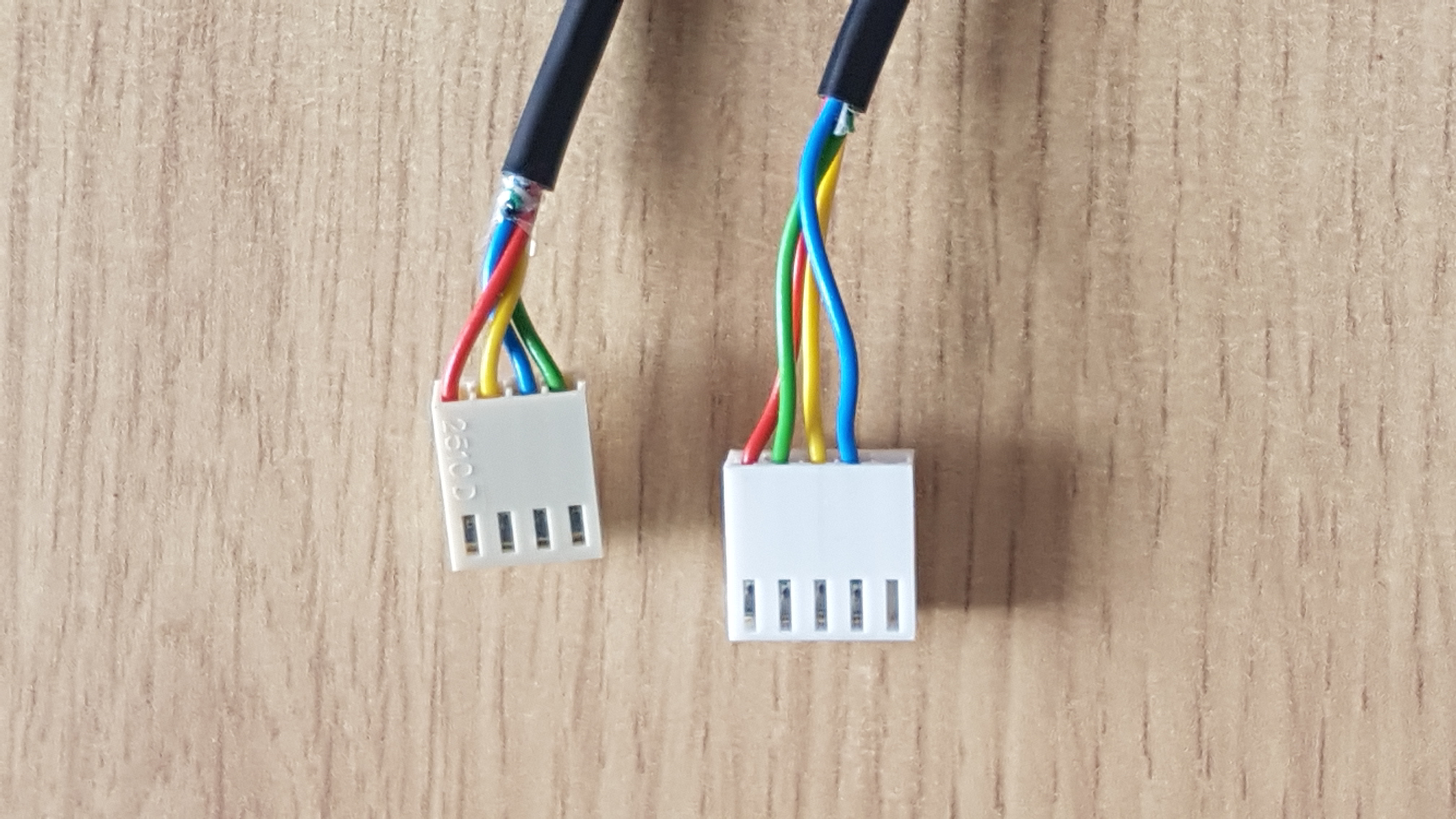
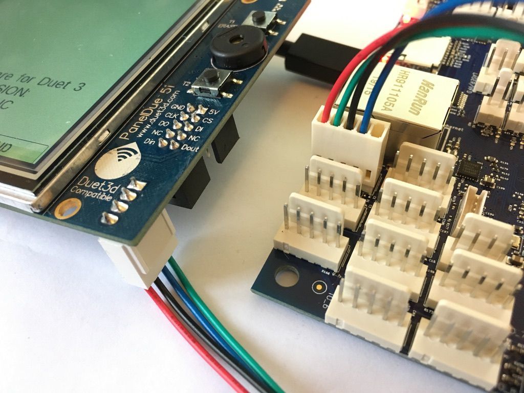
Include M575 P1 B57600 S1 in your config.g to enable the PanelDue.
See Connecting a PanelDue for more information.
¶ Connecting CAN bus expansion boards
Additional expansion boards add further functionality to your Duet 3 mainboard. These are connected by CAN bus. For an overview of connecting these, see CAN connection basics.
If you connect one or more expansion boards via CAN (as shown in the earlier photo), you must install the two CAN termination jumpers on the last board in the chain, but not on any additional boards in the middle of the chain.
For a list of expansion boards that can be connect to a Duet 3 mainboard, see the 'CAN expansion' section of the Duet 3 family page.
¶ Reporting issues
Please use the forum to report any issues: https://forum.duet3d.com/