¶ Introduction
This document is relevant to: All Duet boards
Firmware versions: All versions
Difficulty: Moderate
Time Required: 30 minutes - 1 hour
This guide covers configuring RepRapFirmware for your machine.
If you have any problems with your Duet when using this guide, rather than posting comments, please use our support forum: https://forum.duet3d.com/
¶ Read me first!
RepRapFirmware is supplied as a ready-built binary file; effectively, all Duet mainboards are running the same firmware, though there are differences in the features of each board.
All configuration, and machine-specific parameters, are defined within the /sys/config.g file on the on-board SD card (or on the SD card in the connected Single Board Computer). This includes configuration for network, stepper motors, axis limits, endstops, probes, temperature sensors, heaters, cooling fans and tools.
The SD card also stores system macros. The uses of these include telling the machine what to do when homing, probing, and pausing, resuming, or cancelling a job.
You can edit these configuration files (and sometimes this is required) either in the web interface, or by moving the SD card to a PC and using an ordinary text editor. You can also change these parameters on the fly by sending the appropriate G-codes.
However, creating these configuration files by hand can be tricky. For this reason, we suggest using the RepRapFirmware Configuration Tool to set up your machine's initial configuration. This will create a set of files to go on the SD card, including config.g and system macros for homing, probing, pausing resuming and cancelling, amongst others.
Setting up the configuration requires some basic mechanical and electrical knowledge of the machine the Duet is being connected to. This information can usually be obtained from manufacturer documentation, or a google search. If you are updating an existing machine, the firmware on the existing electronics may report the current configuration by sending M501. In a pinch you can measure. A list of the details needed and common values for them can be found on User manual: Adapting an existing printer to Duet.
¶ Notes
For more detailed description of the structure of the SD card, and description of files, see User manual: SD card
A full explanation of the configuration files that the configuration tool produces are detailed on the wiki page for Configuring RepRapFirmware for a Cartesian printer. If you have a delta, corexy or other printer this guide is still a useful start point, as is the wiki page linked above. After that check the wiki pages for your specific printer type:
Configuring RepRapFirmware for a CoreXY printer
Configuring RepRapFirmware for a Linear Delta printer
Configuring RepRapFirmware for an IDEX printer
Configuring RepRapFirmware for a DLP printer controlled by nanoDLP
Configuring RepRapFirmware for a Hangprinter
Configuring RepRapFirmware for a Polar printer
Configuring RepRapFirmware for a Rotary Delta printer
Configuring RepRapFirmware for a Serial SCARA printer
Configuration RepRapFirmware for a Five bar parallel SCARA printer
Configuring RepRapFirmware for a Robot printer
While RepRapFirmware was originally written for 3D printers, it has evolved to be a very capable controller for other kinds of machines. See:
Configuring RepRapFirmware for a CNC machine
Configuring RepRapFirmware for a Laser engraver/cutter
Configuring RepRapFirmware for OpenPnP
¶ 1. RepRapFirmware Configuration Tool - Start
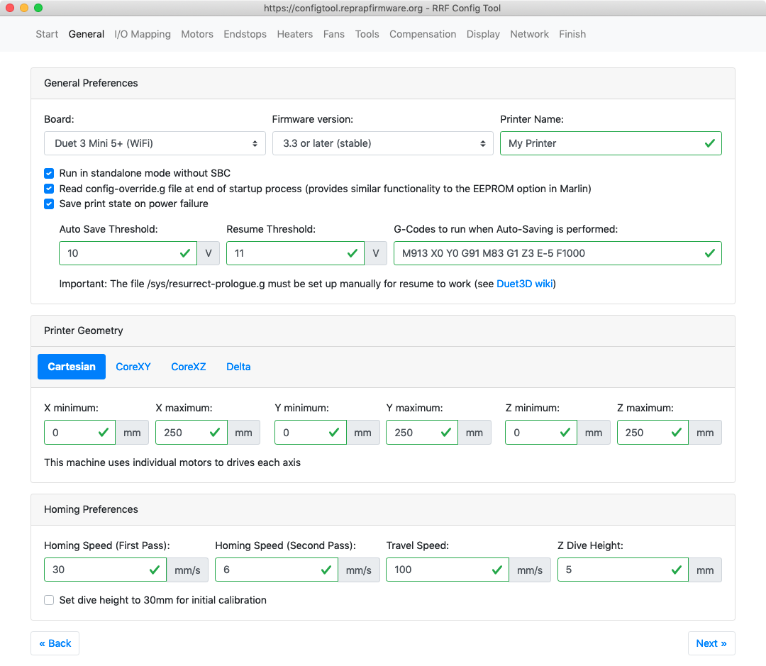
As an example, the images in this guide show the configuration of a Duet 3 Mini 5+ WiFi with a CAN-connected Duet 3 Toolboard 1LC, on a 3D printer with Cartesian kinematics.
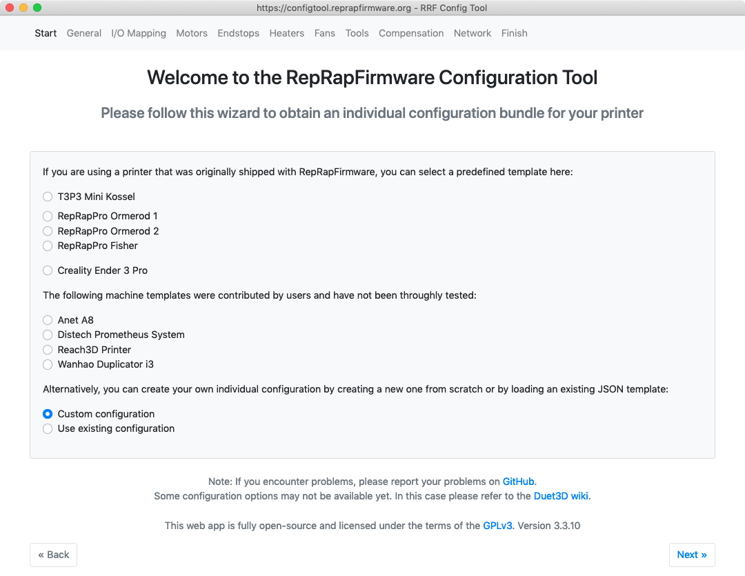 To start configuring your machine, go to the
RepRapFirmware Configuration Tool.
- If you have one of the machines listed, select it to load the default profile for that machine. Otherwise, select 'Custom configuration'.
- If you have already configured your machine, but want to make changes, you can select 'Use existing configuration'. You will be prompted to upload the 'config.json' that is output as part of the zip file at the end of the configuration process.
¶ 2. General
- Choose your Duet board type from the drop down list.
- Choose your firmware version from the drop down list. We recommend using the latest 'release' version of RepRapFirmware. Refer to User manual: Updating firmware.
- Give your printer a name. If you use mDNS (see description here) you can access your printer over the network by name, rather than IP address.
- If you're running your Duet connected to a Single Board Computer (SBC, eg a Raspberry Pi), deselect 'Run in standalone mode without SBC'.
- Select 'Read config-override.g' to enable reading of a file that contains extra, automatically generated, configuration. See M500 for details.
- Select 'Save print state on power failure' to enable your machine to resume printing after a power failure. See User manual: Resume a print after a power failure for details.
Printer Geometry
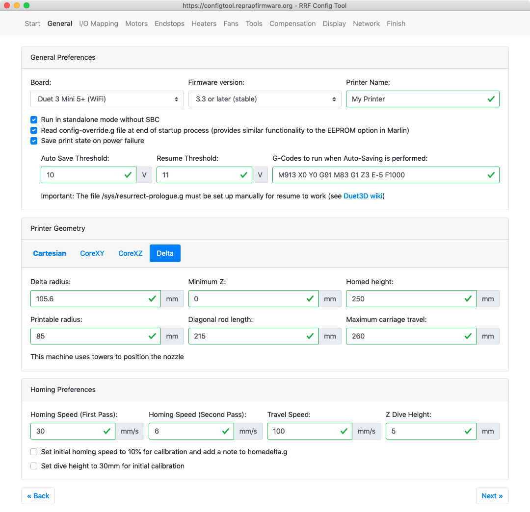
- Choose your printer geometry. The configuration tool only supports Cartesian, CoreXY, CoreXZ and (linear) Delta. If your machine has a different kinematics/geometry, you can still use the configuration tool; select the geometry that most closely matches your machine, then follow the kinematic-specific documentation (see the Notes at the beginning of this guide).
- If you choose Cartesian, CoreXY or CoreXZ, put in the limits for the X, Y and Z axes. This is generally the size of the bed, and the maximum height you can print to.
- The nozzle is at X0 Y0 usually at the front left of the bed; a positive X axis move moves the nozzle from left to right, and a positive Y axis move moves it front to back. If you have a machine where the bed moves in Y, the bed will move from the back to the front; the nozzle moves relatively front to back. A postive Z move will increase the distance between nozzle and bed; the Z axis either moves the nozzle up, or moves the bed down.
- If the nozzle can go over the edge of the bed before hitting the endstop, you can use negative values. For example, if the nozzle goes 20mm over the edge of the bed before stopping at the minimum X endstop, put '-20' in 'X minimum'.
- You can set X0 Y0 to the middle of the bed. See User manual: Centering the bed or setting the bed origin.
- If you choose Delta, you will need to enter some Delta-specific geometry information. This doesn't have to be precise; you will need to calibrate the Delta later anyway. See Calibrating a delta printer for details.
- X0 Y0 will be in the center of the bed.
Homing preferences
- This section defines homing speeds and the amount Z lifts between probing points. Leave as-is unless you know the speeds and Z dive height you want to use.
- There are a couple of check boxes you can tick to increase these heights if this is the first time setting up a machine, and want to be cautious.
¶ 3. I/O Mapping
If you're configuring for RRF 2.x or earlier, this page only gives you the option of adding expansion boards to the configuration.
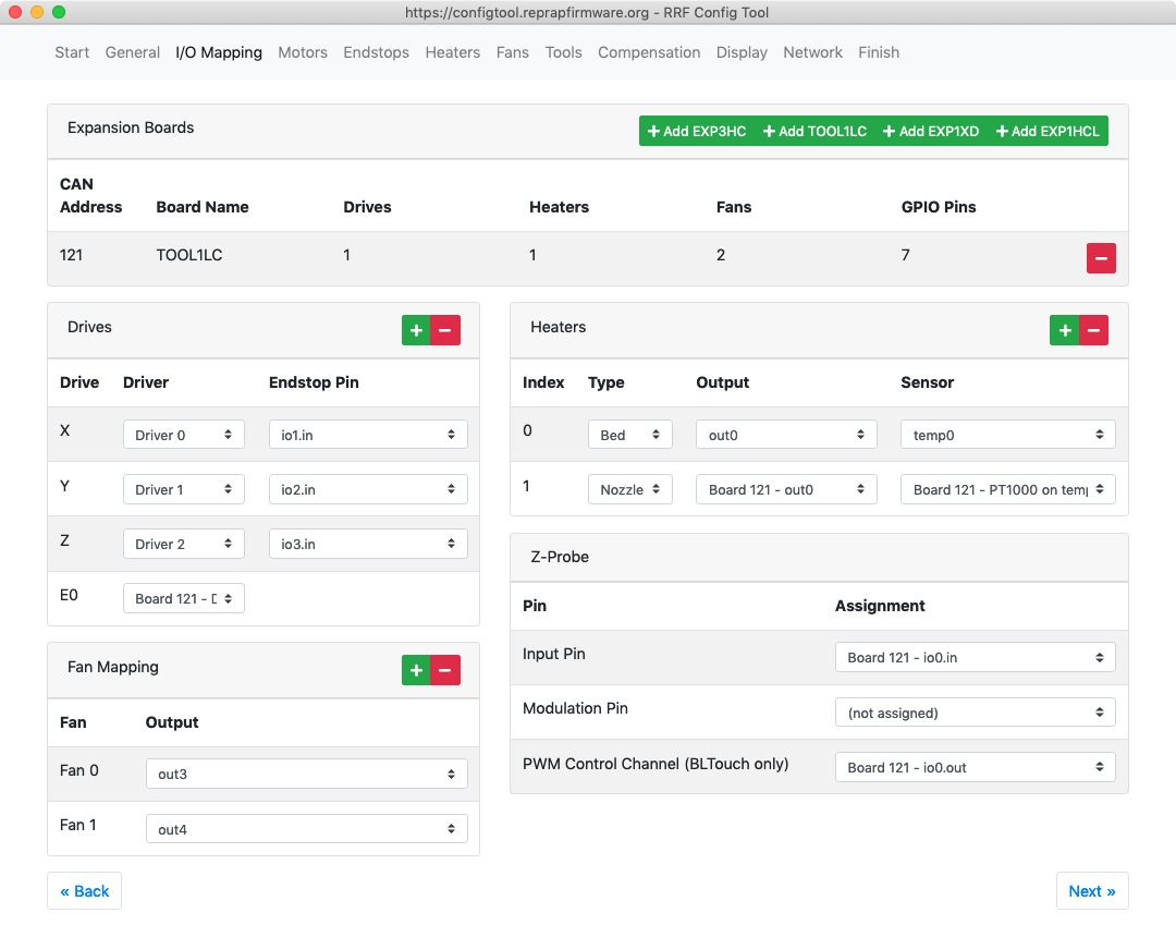
- Add any expansion boards connected to your mainboard. This can be DueX2/5 for Duet 2 WiFi/Ethernet, or any of the CAN expansion boards for Duet 3.
Drives
- Define which axis drive motor connects to which driver on the Duet (mainboard or expansion board), and the input pins that the endstop for that axis is connected to, if required.
- Note that RRF supports exactly one endstop per motor, at one end of the axis.
- Note the configuration tool can currently only create X, Y, Z and E (extruder) axes. If you need additional axes, you will need to create them manually by editing config.g.
- Note the configuration tool does not support creating axes with multiple motors, where the motors are on different drivers, yet.
- To create additional axes, or an axis with multiple motors on different drivers, see User manual: Configuring stepper motors.
Fan mapping
- Define which pins the fans connect to.
- FAN 0 is usually the part cooling fan. FAN 1 is usually the hot end cooling fan, and is often set to thermostatic (ie temperature controlled) operation.
- See User manual: Connecting and configuring fans for details of connecting and configuring two, three and four wire fans.
Heaters
- Add or remove heaters as necessary.
- Define each heater as a Bed, Nozzle or Chamber heater, and which output pins the heater will connect to. See User manual: Heater overview for details of heater support.
- Define the temperature sensing channel for each heater. Thermistors and PT1000 temperature sensors can be connected directly to the board, which PT100 and thermocouples need an extra temperature daughterboard.
- See User manual: Choosing temperature sensors for more details.
Z-probe
- Choose the input pin for you probe.
- Very few probes are modulated; unless you know your's is, leave blank.
- Only probes that need to be deployed/retracted, like the BLTouch, need a PWM contol channel set.
- See User manual: Choosing a Z probe for more details on choosing a suitable probe, and User manual: Connecting a Z probe for connecting and configuration.
¶ 4. Motors
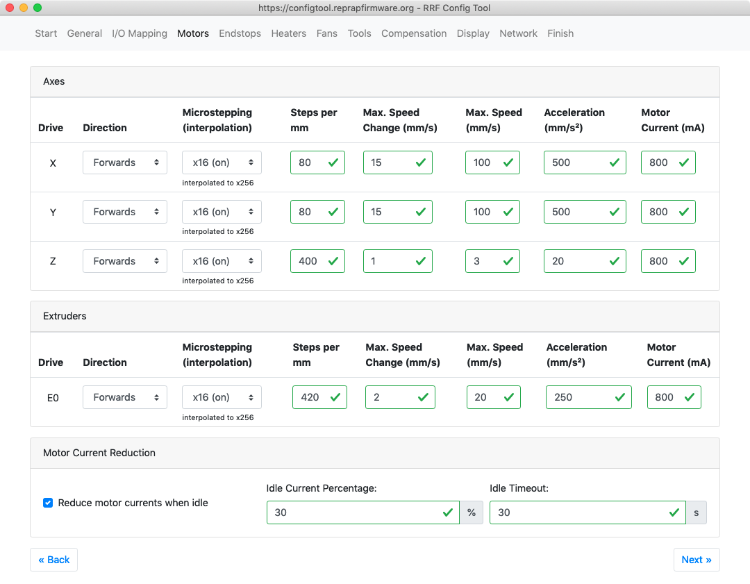
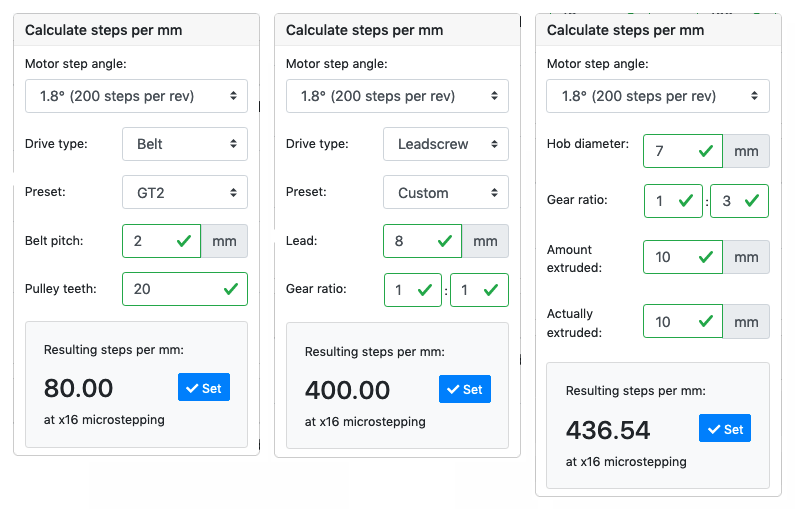 This page defines stepper motor direction, microstepping, steps per mm, speeds, acceleration and current.
Axes and extruder
- Motor settings will depend on your choice of motor, motion system and kinematics. It's best to start with conservative settings, and increase them as you tune your machine.
- We generally advise to use x16 microstepping, with interpolation; stepper motors are usually not capable of higher resolution or repeatability when using higher microstepping modes.
- For steps per mm, there is a calculator built in to help you calculate the correct number. It can calculate steps per mm for belt, leadscrew and extruder.
- Maximum speed change, maximum speed and acceleration, will depend on your choice of motor, motion system and kinematics. It's best to start slow, then increase to find the limit (ie where each axis looses steps, or there is too much vibration), then reduce until you find a safe setting that performs as desired.
- A typical setting for motor current is 60% to 85% of the rated current of your stepper motors.
- If configuring for RRF 2.x and earlier, you will have the option to select which motor driver each drive is connected to.
Motor current reduction
- Motors can produce an audible hiss when stationary, as well as heat up. The firmware can reduce the motor current substantially when idle, without losing position.
- These two boxes set the idle current, and how long before it is enabled after the last movement of any axis.
¶ 5. Endstops
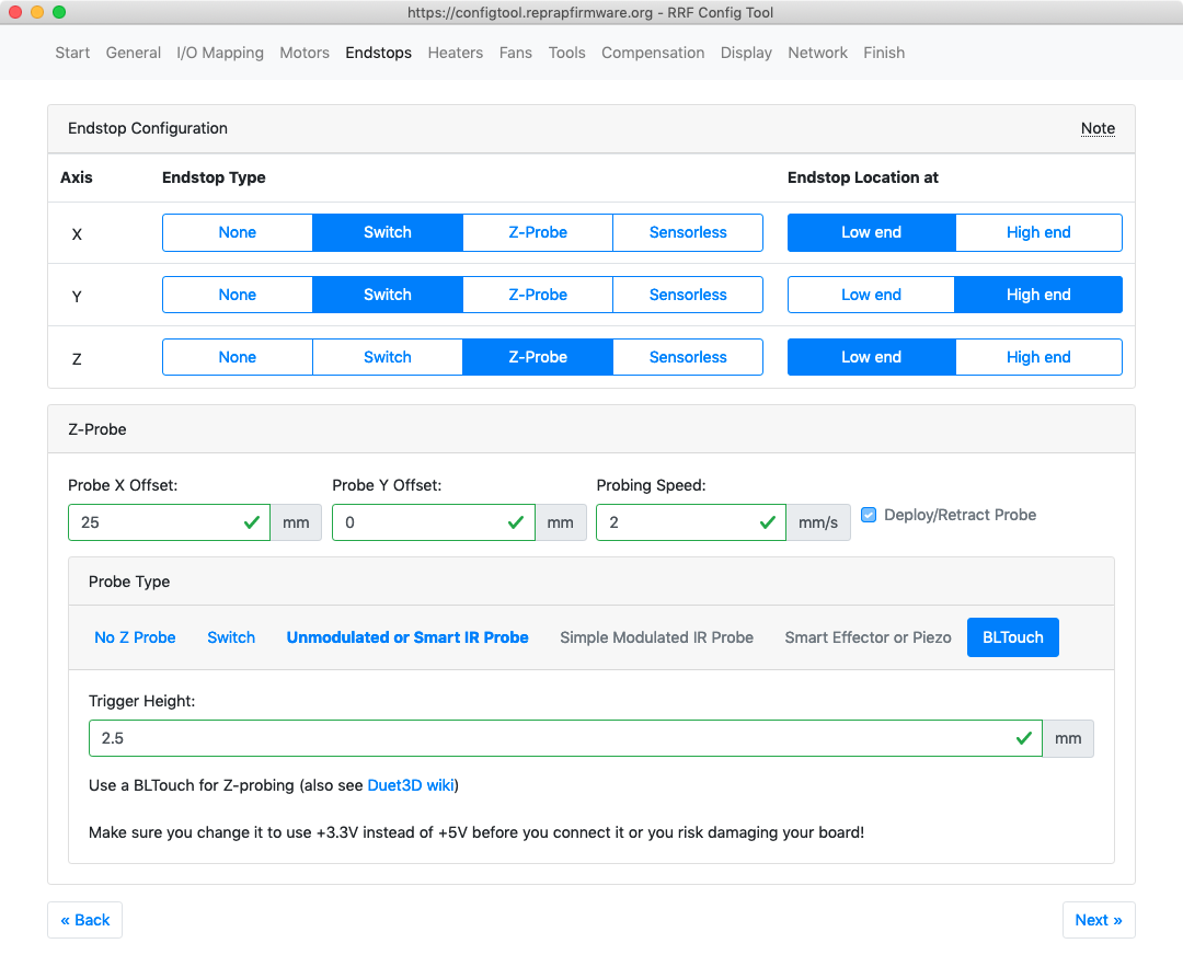
- Set the endstop type and location.
- Some endstop type options will be unavailable if they have not been configured on the I/O Mapping page, Drives section (RRF 3.x).
- Sensorless homing is when the motor stalls at the end of it's travel. See User manaul: Stall detection and sensorless homing for details.
- If configuring for RRF 2.x and earlier, instead of 'Switch', you will have the option to select either 'Active high (NC - Normally Closed)' or 'Active low (N0 - Normally Open)' switch types.
- For the 'Endstop location', the 'Low end' is where the axis is at it's minimum. For X and Y, this is the minimum set on the General page, Printer geometry section. For Z, this is where the nozzle touches the bed (either the bed moves up to touch the nozzle, or the nozzle moves down to touch the bed), and is usually Z0.
Z Probe
- Some Probe types will be unavailable if they have not been configured on the I/O Mapping page, Z Probe section (RRF 3.x).
- Set probe offsets, probing speed and trigger height. These will be measured during commissioning; see Test and calibrate a Z probe
- Depending on your probe type, set trigger value, recovery time and Servo Control Channel (BLTouch, RRF 2.x only), though generally default values should be fine.
- See User manual: Choosing a Z probe and Connecting a Z probe for more details and options.
¶ 6. Heaters
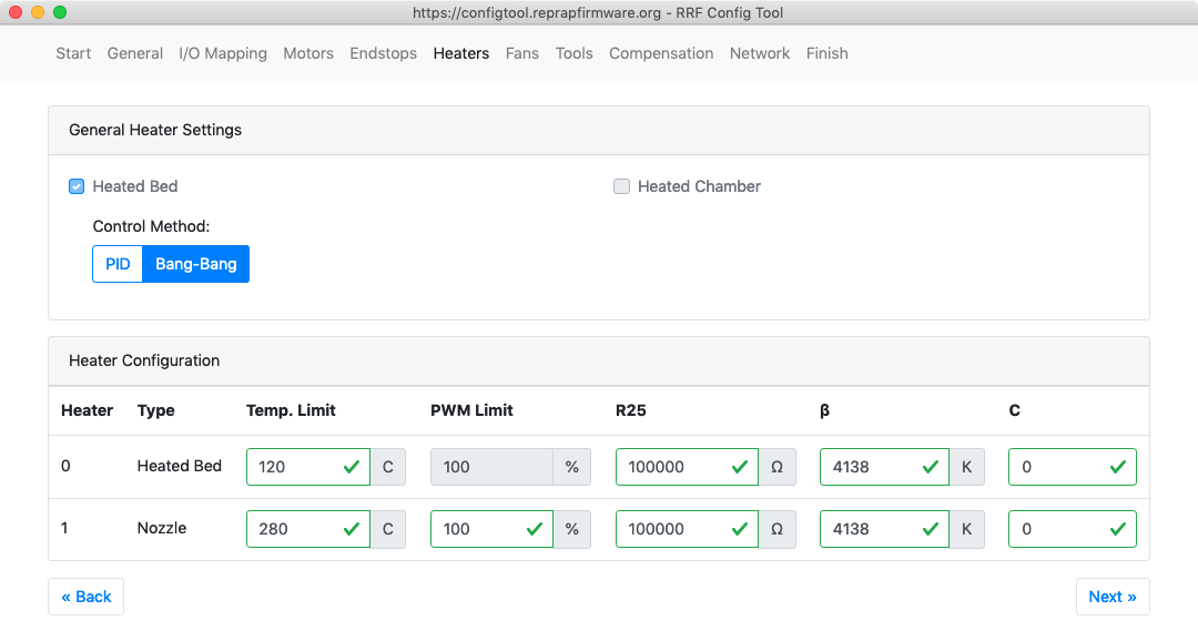
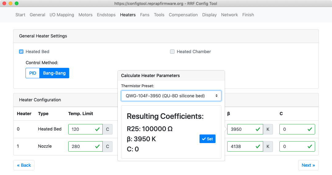
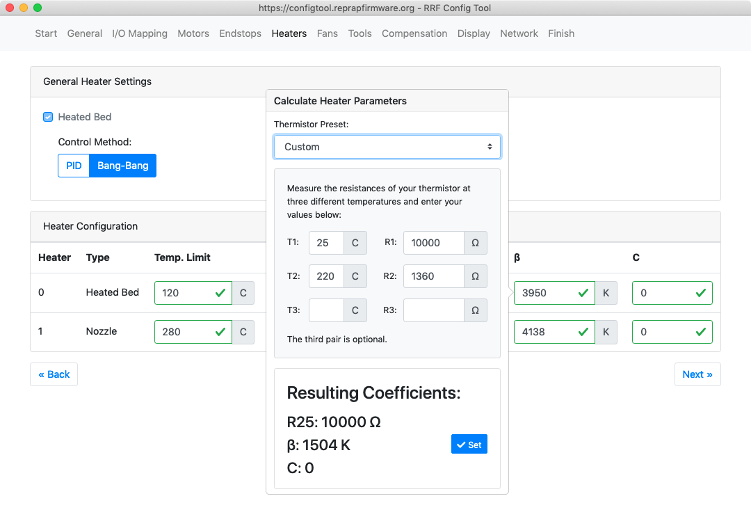 Define the heaters connected to your machine.
- If you selected RRF 3.x on the 'General' page, the type (bed, chamber, nozzle), number and output pins of heaters, and the temperature sensor type and input pins, are defined on the 'I/O mapping' page.
- If you selected RRF 2.x on the 'General' page, define here the type (bed, chamber, nozzle), number and output pins of heaters, and the temperature sensor type and input pins.
General Heater Settings
- If configured, bed and/or chamber heaters can be set to 'PID' or 'Bang-bang'. It doesn't matter too much which you choose, as all heaters will be tuned during commissioning using M303.
Heater configuration
- The 'Heater configuration' section sets heater temperature and PWM limits, and the parameters for thermistors.
- IMPORTANT! To get accurate temperature readings, you must enter parameters that match your temperature sensor. Otherwise your machine may over or under report the temperature! Use the manufacturer's specification for the sensor, if possible.
- Clicking on 'R25', 'Beta' or 'C' parameter boxes for a heater will bring up a pop-up, allowing you to select your thermistor type from a drop-down list.
- If your particular thermistor is not listed, clicking 'Custom' on the drop down list shows a thermistor parameter calculator. Enter values for it to calculate the thermistor coefficients for you.
- If you know your thermistor parameters, you can input them directly in the R25, beta and C boxes.
- If you selected PT1000, PT100 or thermocouple as the temperature sensor for a heater, ignore the values; they will be overwritten with appropriate values for your chosen sensor.
¶ 7. Fans
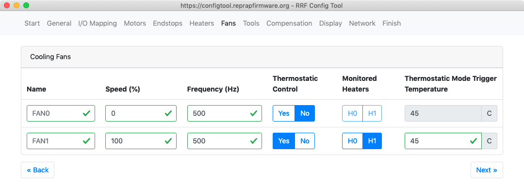
- In a 3D printer with a single print head, FAN 0 is usually assigned as the print cooling fan and FAN 1 for the hot end heatsink fan. This is the easiest configuration to use because it's what most G-code slicing software (and the firmware, in RRF 2.x and earlier) expects by default.
- Set the initial fan speed and PWM frequency. Check your fan's specification to find what PWM frequency it works best at.
- Each fan can be configured in firmware as a gcode controlled fan or as a thermostatically-controlled fan. If you choose thermostatic control, set the heater that is monitored, and the temperature that triggers the fan to start.
- If configuring for RRF 2.x and earlier, you will have the option to add/remove fans, and to invert the fan output. Fans are mapped to their corresponding output pins by default, but can be remapped using M106 with the A parameter.
- See User manual: Connecting and configuring fans for more details.
¶ 8. Tools
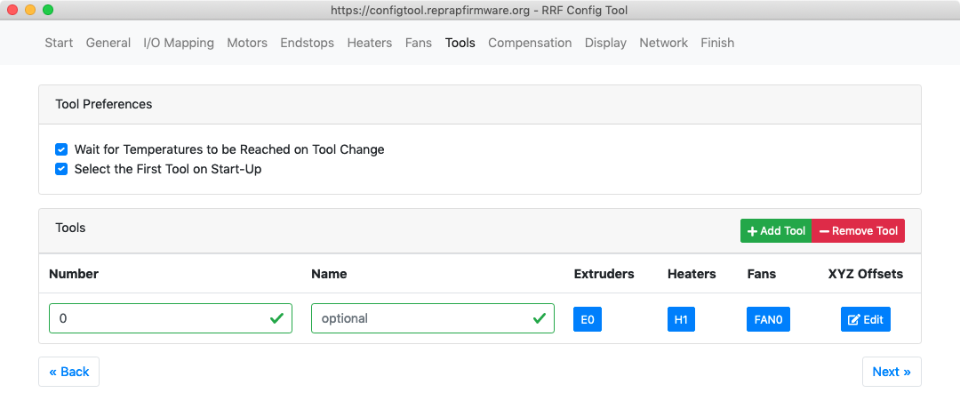
- It is usually best to select 'Wait for the tool temperature to be reached on tool change'
- 'Select the first tool on Start-up' adds the relevant T code to the end of the configuration. Note that in RRF 3.3 and later, tool change macros will run at startup. See Multiple tools and tool change macros for details.
Tools
- In this section you can add and/or remove tools. For a single nozzle/extruder setup, you only need one tool.
- Tool numbering starts from 0 usually. RRF 3.3 supports the creation of up to 50 tools (numbered 0 to 49).
- For each tool, set the tool number, name (optional), and the extruder drives, heaters and print cooling fans.
- If you have a multi-tool setup, you can define the print cooling fan of each tool as part of the tool. This gets around the issue of Slicer software not supporting multiple part cooling fans.
- Thermostatically controlled fans are not configured as part of the tool.
- If you have a tool that uses multiple extruders (i.e. a mixing hot end), if you select more than one extruder drive an additional column with mixing ratios will appear. You can then define the mixing ratio for each extruder drive.
¶ 9. Compensation
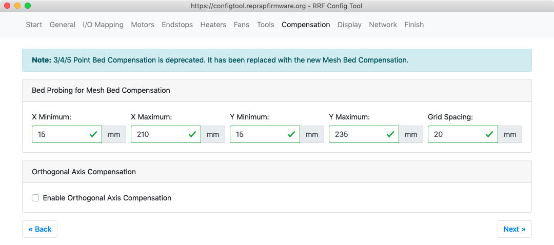 Bed probing for Mesh Bed Compensation
- Mesh Bed Compensation allows the printer to adjust the nozzle height during printing to compensate for an uneven bed or for sag in the gantry.
- Set the bed area to be probed for Mesh Bed Compensation.
- Some areas of the bed may not be reachable by the probe if it has a large offset from the nozzle; account for this offset in the minimum and maximum numbers.
- Set the grid spacing. Up to 441 probe points can be sampled for each mesh.
- See Mesh Bed Compensation for full details.
Orthogonal Axis Compensation
- RepRapFirmware allows you to compensate for the fact that your machine's X, Y, and Z axes may not have been assembled at perfect right angles.
- Generally, you'll need to be able to print a reference object, and then measure it, before being able to input numbers into these boxes.
- See M556 for details.
¶ 10. Display

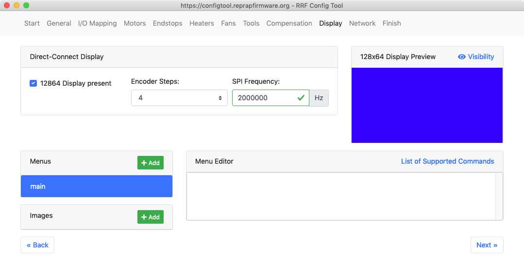 This page is only displayed if your Duet supports a 12864 display, i.e. Duet 3 Mini 5+ or Duet 2 Maestro.
- Select 12864 Display present if you are connecting this display.
- If selected, there are some other options to choose, such as Encoder steps and SPI Frequency. See User manual: Connecting a 12864 display for details.
- For the menu system, see User manual: 12864 display menu system
- Support for 12864 displays on Duet 2 WiFi/Ethernet has been added, but requires RRF 3.2 or later and extra hardware and wiring loom. See User manual: Connecting a 12864 display for details.
¶ 11. Network
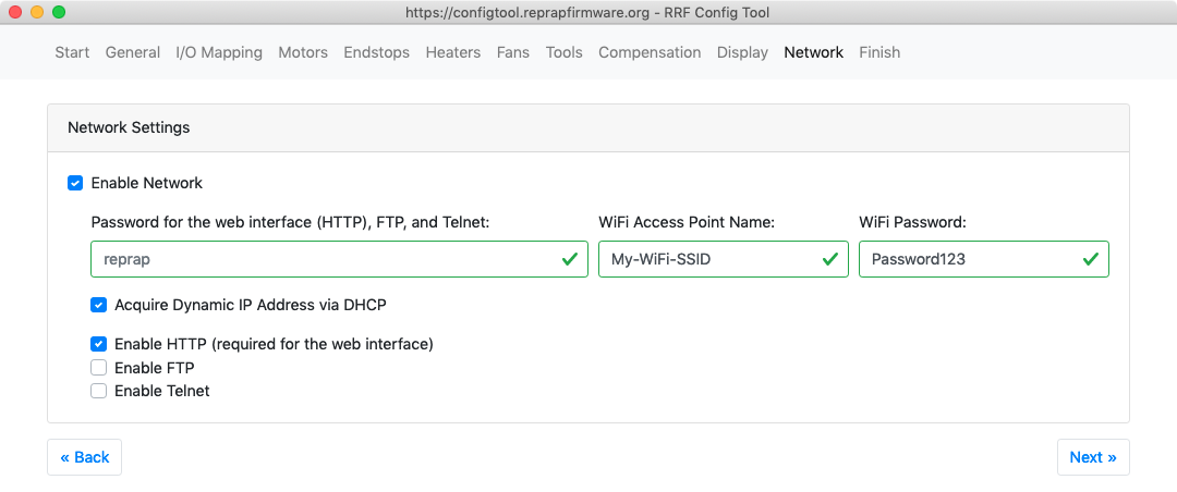
- Almost certainly, you'll want to 'Enable Network'
- Enter a password, to require password access to DWC. Note that as the password is sent unencrypted it does not (nor is it intended to) offer a high level of security. But on machines that are (say) on a network, it might prevent idle messing about.
- If you are configuring a WiFi-equipped Duet, you can enter the WiFi SSID name and password. A configuration file called 'runonce.g' will be created, which will run and then be deleted on reboot, which will configure the Duet's WiFi.
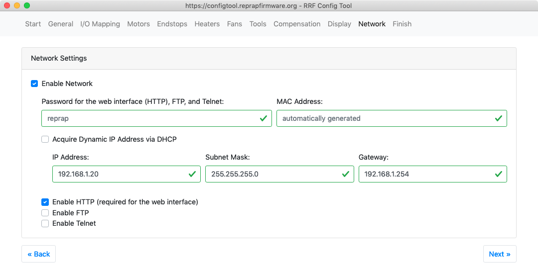
- Acquire Dynamic IP Address via DHCP
- If selected, your Duet will acquire it's IP address from the network DHCP server.
- If not selected, you can define the IP address, Subnet Mask and Gateway address to use. If setting these on a WiFi-equipped Duets, these will be added to the 'runonce.g' configuration file, and set on the next reboot after uploading to the Duet. On Ethernet-equipped Duets, these parameters are added to the M552 command that enables networking, in config.g.
- Enable HTTP to allow access to the Duet Web Console
- Enable FTP and Telnet to have those services available on the Duet.
- See User manual: Networking for more details.
¶ 12. Finish
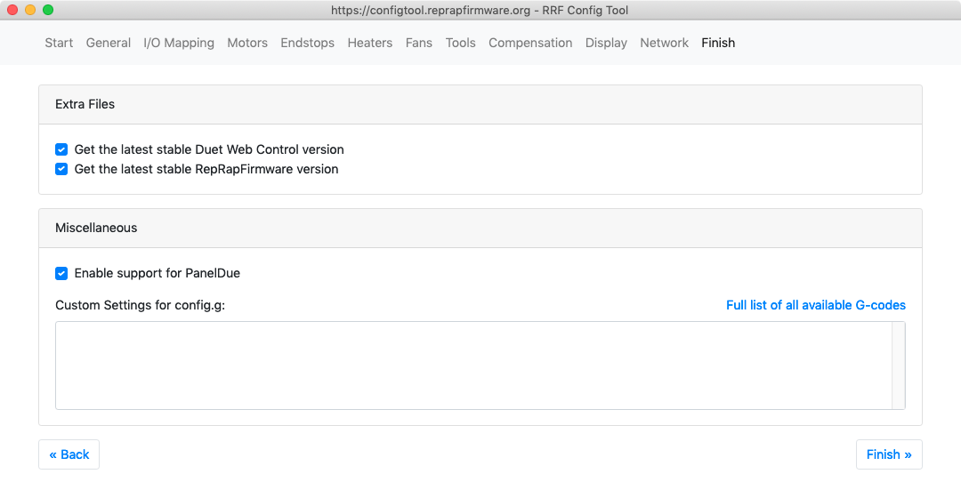
- If you selected 'Get the latest Duet Web Control version' the current release of DWC will be added to the configuration bundle.
- If you selected 'Get the latest RepRapFirmware version' the current release of RRF will be added to the configuration bundle.
Miscellaneous
- If you are connecting a PanelDue, tick the 'Enable support for PanelDue'. This adds the GCode that initialises communication with the PanelDue to the configuration. See User manual: Connecting a PanelDue for more details.
- There is then a space for you to enter any custom GCode that you want to run at the end of config.g.
¶ 13. Download configuration .zip file
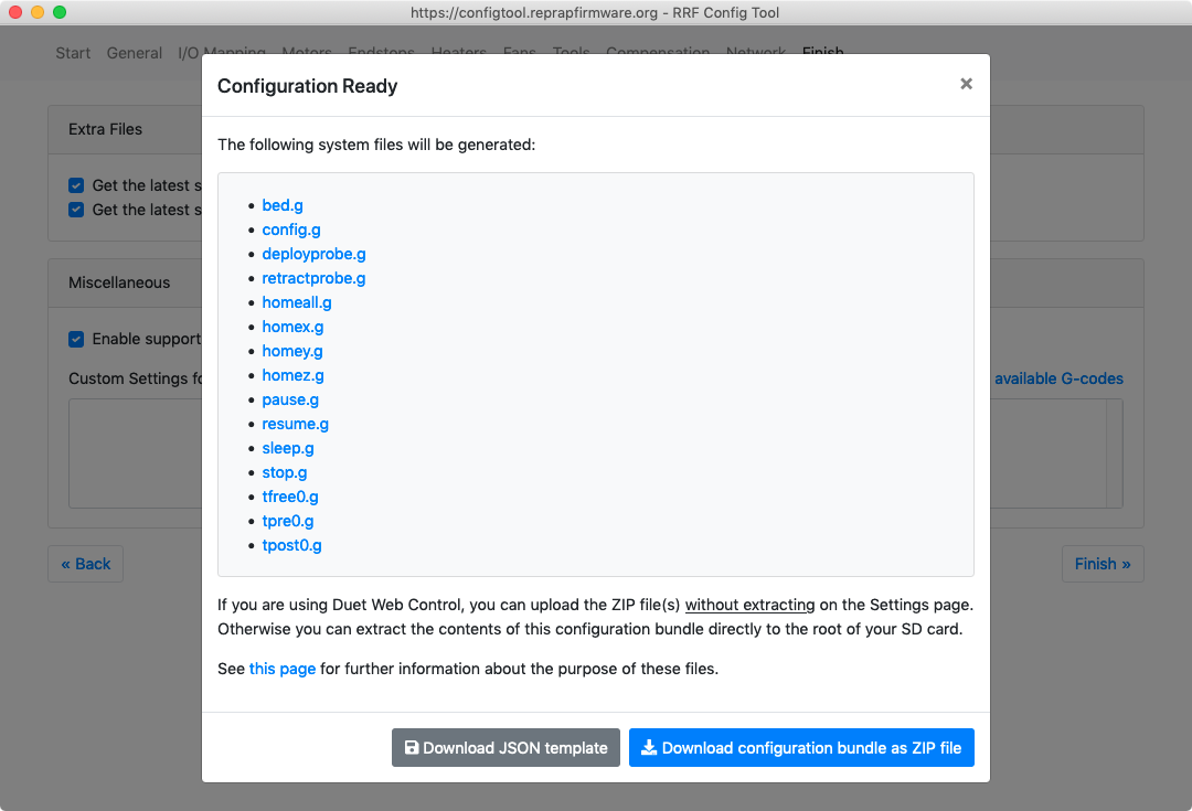
- The RepRapFirmware Configuration tool will automatically generate configuration files for you based on your selections.
- The configuration files that will be created are shown. You can click on them to see the contents before downloading.
- Download the configuration .zip file and place it in a folder on your PC that can be easily accessed.
¶ 14. Upload configuration via Duet Web Control
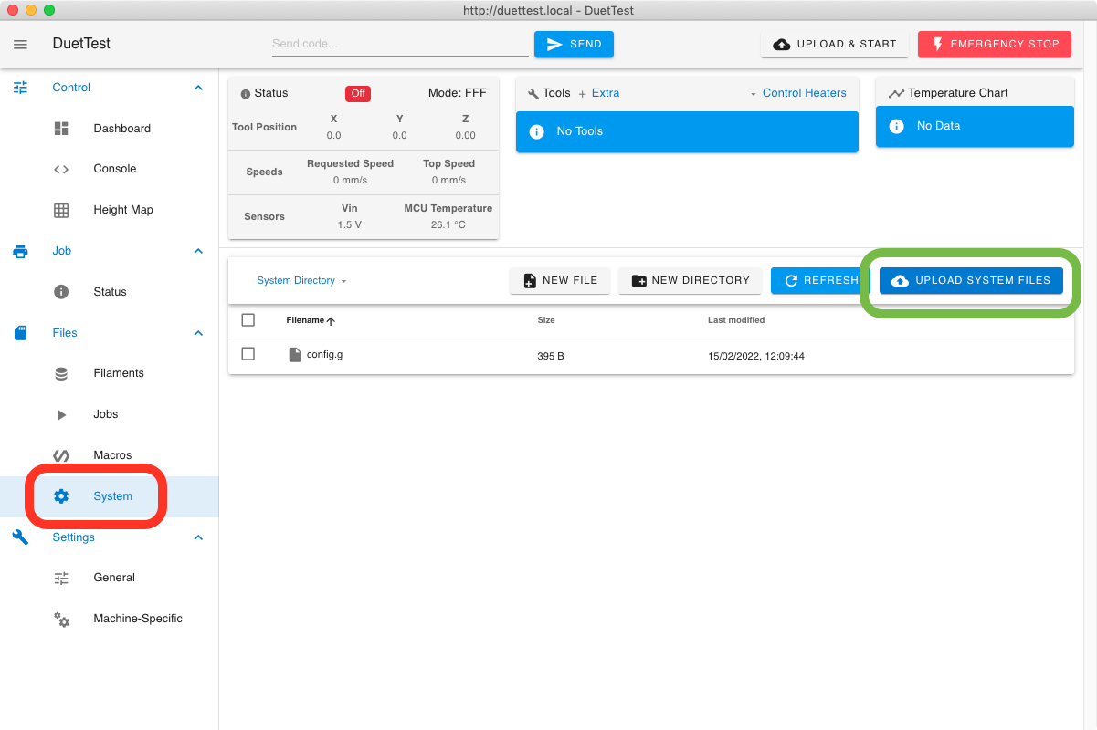
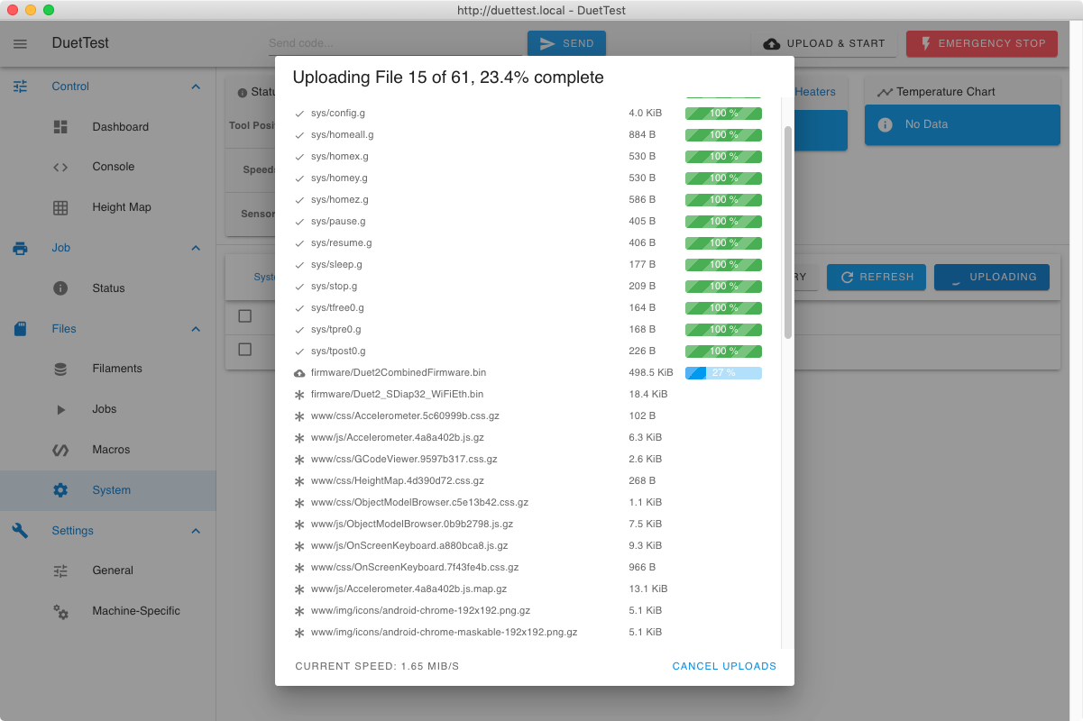 This and following steps use Duet Web Control (DWC) to setup and control the Duet. See User manual: Duet Web Control for full documentation.
- Open your browser and navigate to:
duettest.local(assuming the printer name is still "duettest", and your network setup supports mDNS), or- the IP address of the printer (if this has changed from when setup, either your router should be able to report the addresses of everything connected, or connect to the Duet via USB and send M552)
- Navigate to the Files > System page and click "Upload System Files".
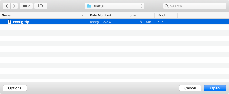
- Navigate to the folder where you saved the configuration .zip file in step 13, and select "Open".
- The files in the config.zip file will upload.
- If you selected 'Get the latest Duet Web Control version' and/or 'Get the latest RepRapFirmware version' in step 12, the current release of DWC will be uploaded to the /www folder on the SD card, and the current release of RRF will be uploaded to /firmware (RRF 3.3 and later) or /sys (RRF 3.2.2 and earlier).
¶ 15. Reboot the Duet
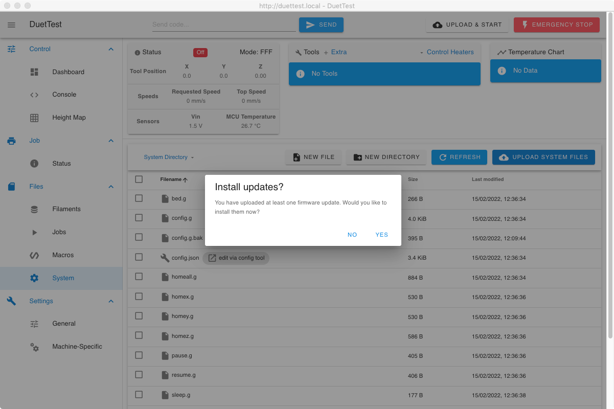
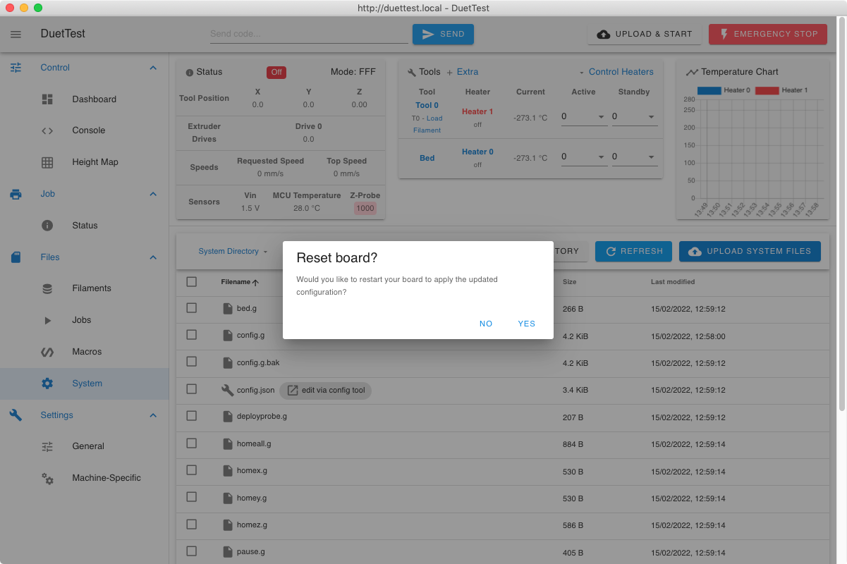 Depending on the options you have selected, the firmware may ask to install firmware or reboot.
- The firmware regards uploading a config.zip or config.g file, or editing config.g in the System Editor, as a change to the configuration. Configuration changes will not take effect until the device has been rebooted.
- If you selected 'Get the latest Duet Web Control version' the Duet will ask you if you want to install the firmware updates:
- Select 'Yes' and the firmware will be installed, and the board reset at the end.
- Select 'No' and you will be asked if you want to reset the board; you do.
- If you selected 'Get the latest Duet Web Control version', the browser window will refresh with the latest version of DWC showing. You should then be asked if you want to reset the board; you do.
- If you selected both of the above, you can choose not to install the firmware, but you should reset the Duet.
- If you selected neither of the above, the Duet should still notice that you have uploaded a configuration file and will ask to be rebooted.
- Select Yes to reboot the Duet and apply the new configuration.
- A configuration change sent via a G-Code console will take effect immediately, but will be lost when the device is rebooted (unless the system file has been edited to also reflect the change).
¶ 16. Configuration complete!
If your Duet has rebooted and mains power is applied, IMMEDIATELY check that your new configuration is not heating heaters/moving axes/starting spindles or any other unexpected and unwanted behaviour. If it is, TURN OFF THE POWER! You can investigate any problems and check configuration by powering the Duet with USB power only.
With your new configuration in place, move on to the Commissioning guide to check all parts are working correctly.
